Lightning Protection International LSR2 Instruction Manual

Commercial in Confidence Document ID: LPIDOC-26-4000 Version: 2.4 05/05/2022 Page 1
Copyright © 2022 LPI
TECHNICAL DATA SHEET
LPI® Lightning Strike Recorder LSR2
Features
•7 Digits
•Up to 9,999,999 counts
•Testable using LSR-Tester
Installation/ Operating Instruction
The LSR2 can be installed at any location on the down-conductor route between the air terminal and the earthing
system. Where possible, avoid installing the LSR2 in a position where it is exposed to direct sunlight. This can be
achieved by installing the LSR2 in a suitable mounting cabinet.
The LSR2 should be mounted in line with the down-conductor as shown in Figure 1. If using flat down-conductor
use the plastic spacer provided, as per Figure 2. To remove or relocate the LSR, use a small flat bladed screwdriver
to release the clip on the latching mechanism on the cable tie.
Product Description
LPI® Lightning Strike Recorder (LSR2) is a lightning event counter. The LSR2
is simply mounted at any location along the down-conductor route. Its purpose
is to record the number of lightning strikes captured by the lightning air
terminal and conveyed by the down-conductor.
The LSR2 operates by sensing current by means of an inductive pick up loop.
The loop passes along the inside surface of the bottom of the enclosure. This
loop detects lightning current impulses on the down-conductor and sends a
trigger to the counter, which turns the counter over to register the event. The
Recorder is mounted in a polycarbonate enclosure rated IP 65.
Figure 1
Figure 2

Commercial in Confidence Document ID: LPIDOC-26-4000 Version: 2.4 05/05/2022 Page 2
Copyright © 2022 LPI
TECHNICAL DATA SHEET
Features
•Ideal for maintenance and testing of LPI®
Lightning Strike Recorders
•Simple operation
•Portable
LPI® Lightning Strike Recorder Tester LSR-TESTER
Product Description
LPI® Lightning Strike Recorder Tester (LSR-TESTER) is a
high current device designed to trigger a reading on an LPI
Lightning Strike Recorder (LSR1 or LSR2, hereafter simply
referred to as “LSR”).).
The tester is light, compact, and is powered by 8 x AA NiMH
rechargeable batteries.
Figure 5: Step 3
Figure 4: Step 2
Figure 3: Step 1
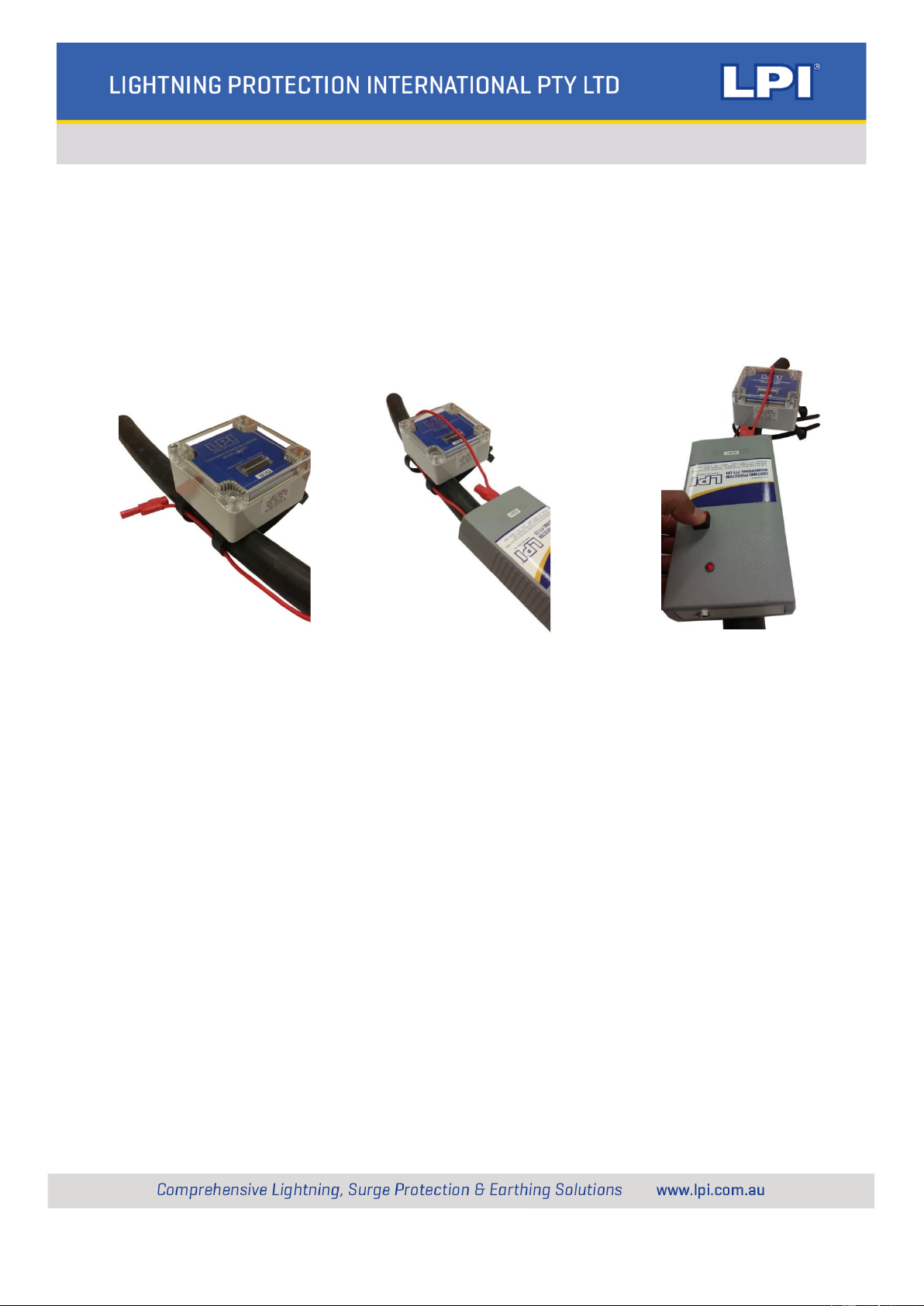
1. To test the LSR, the supplied ‘pulse cable’ is positioned parallel to the down-conductor, through the
mounting saddles as shown in Figure 3.
2. Complete the loop around the LSR, making sure that pulse cable is positioned vertically across the
top of the LSR as shown in Figure 4.
3. Holding down the red button initiates the impulse circuit charging and firing process. Correct charging
operation is indicated by the illumination of the red LED, as shown in Figure 5.
4. After a period of 10-15 seconds an audible ‘clunk’ should be heard. This indicates that the charging
process has finished and a current pulse has been sent through the pulse cable. If the LSR and LSR
Tester are working correctly, the strike count on the LSR will increase by one (1).
If the LED fails to light when pressing the red button, or if no ‘clunk’ is heard after a period longer than 30
seconds then the batteries need to be recharged using the supplied charger. The charger unit has two
indication LEDs to indicate charger power and charging status.
Press and hold the charging button for up to 1 second to start charging the battery. The LED will indicate
RED.
Once a battery has been fully charged, the charging LED will turn GREEN.

Commercial in Confidence Document ID: LPIDOC-26-4000 Version: 2.4 05/05/2022 Page 3
Copyright © 2022 LPI
TECHNICAL DATA SHEET
Description
Lightning Strike Recorder Tester
Impulse Output
2 kA Peak Simulated Lightning
Impulse
Open Circuit
Output
55 Volts
Time Between
Impulses
20 seconds
Display
Red “Testing” LED Indicator
Dimensions
190 (L) x 100 (W) x 35 mm (H)
Mounting
Portable Unit
No mounting required
Construction
Polycarbonate Enclosure, IP 30
rating
Colour
Light Grey
Weight
0.58 kg
Working
Temperature
-12ºC to 65ºC
Batteries
8 x AA 2000 mAh NiMH
Rechargeable
Recharge time up to 16 hours
Description
Lightning Strike Recorder
Current
Sensitivity
1500 A 8/20 µs
Operating
Range
Min. 1500 A, 8/20 µs
Max. 220 kA, 8/20 µs
Display
Mechanical 7-digit display*
(non-resettable)
Dimensions
100 (L) x 100 (H) x 55 mm (D)
Weight
0.56 kg
Mounting
Releasable UV resistant plastic
cable ties
Suitable for up to 40 mm cable or
50 x 5 mm flat tape
Construction
Polycarbonate Enclosure
Colour
Light Grey
Environment
IP 65 (IEC 529)
Working
Temperature
-12ºC to 65ºC
Warranty
This product is guaranteed to be free from materials and workmanship defects for a period of 5 years from the
date of shipment from the manufacturer.
As lightning is a natural event containing unpredictable energy levels, 100% protection is not guaranteed. These
energy levels may exceed the product rating. In this case the manufacturer’s liability is limited to repair or
replacement at the manufacturer’s discretion.
This warranty does not offer any cover for consequential damage, loss of operation or loss of profit.
Note: Handling, transportation and shipment of the LSR2 may result in
slight displacement of the digits of the mechanical counter inside the
unit. This aspect does not affect the performance of the counter.
However, the digits can be easily realigned by turning the LSR2
upside down and tapping it lightly on a solid object.
Product Code: LSR2
Technical Data
Product Code: LSR-TESTER
Popular Cash Counter manuals by other brands

UNISource Corporation
UNISource Corporation FC-8300 Operation manual

DR. JOHANNES HEIDENHAIN
DR. JOHANNES HEIDENHAIN VRZ 560 operating instructions

Nautilus Hyosung
Nautilus Hyosung Monimax 5300CE installation manual

Met One Instruments
Met One Instruments GT-526S manual

Delfield
Delfield Shelleysteel SH-2-NU Specifications

Magnescale
Magnescale LH71 Series quick start guide