Page 2 of 4
TX30 PROTOCOL TRANSLATOR
Version 0.4 OWNER’S MANUAL 06/28/2022
www.lightronics.com
Lightronics Inc 509 Central Drive Virginia Beach, VA 23454 Tel 757 486 3588
DESCRIPTION
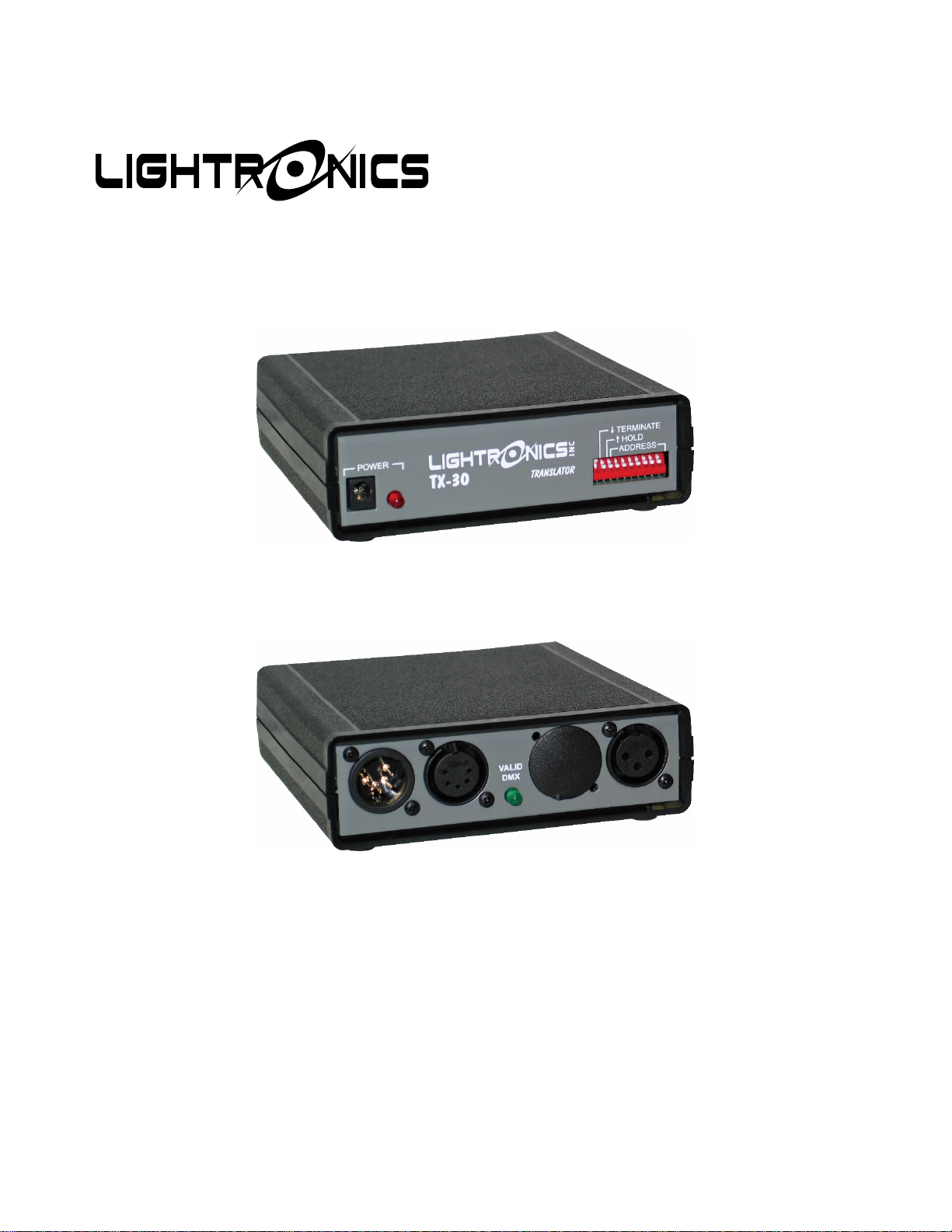
The TX30 is a compact in-line translator which
receives DMX512 and transmits the Lightronics
(LMX-128) multiplex protocol. This is an industry
standard multiplex protocol and MAY be compatible
with other manufacturers’ multiplex devices. The
unit is powered by the LMX dimmer chain to which it
is connected or may be powered by an external
plug-in power supply.
CONNECTIONS
DMX is received via a 5 pin male XLR connector.
LMX output is via a 3 pin female XLR connector. A
5 pin female XLR is also provided for the DMX “pass
thru”. LED indicators display power and input signal
status.
EXTERNAL POWER SUPPLY
Input Voltage: 120VAC
Output Voltage: 24 VDC
Output Current: 1.0 Amp
Connector: 2.1mm female connector
The TX30 will operate using an external power
supply which provides anywhere from 12 to 24 Volts
AC or DC. The supply must be rated for least at 600
mA. If a DC supply is used, the center pin of the
connector MUST BE THE POSITIVE output of the
supply.
OPERATION
The TX30 translates and sends LMX-128
automatically when power is applied and a DMX
signal is present. LED indicators show the power
and DMX incoming signal status.
CHANNEL ASSIGNMENT
The TX30 translates 192 channels at a time. Eight of
the DIP switches on the front of the unit are used to
select the starting channel of the 192 channel block.
When all switches are down, channels 1 - 192 are
selected. Channel selection is incremented two
channels at a time. A table of address switch
settings is included at the back of this manual.
DMX TERMINATE
DIP switch number 1 will terminate the DMX input
bus when it is in the DOWN position.
HOLD FUNCTION
DIP switch number 2 activates a "hold" function.
When in the UP position, channel outputs remain at
their current levels indefinitely upon a loss of DMX.
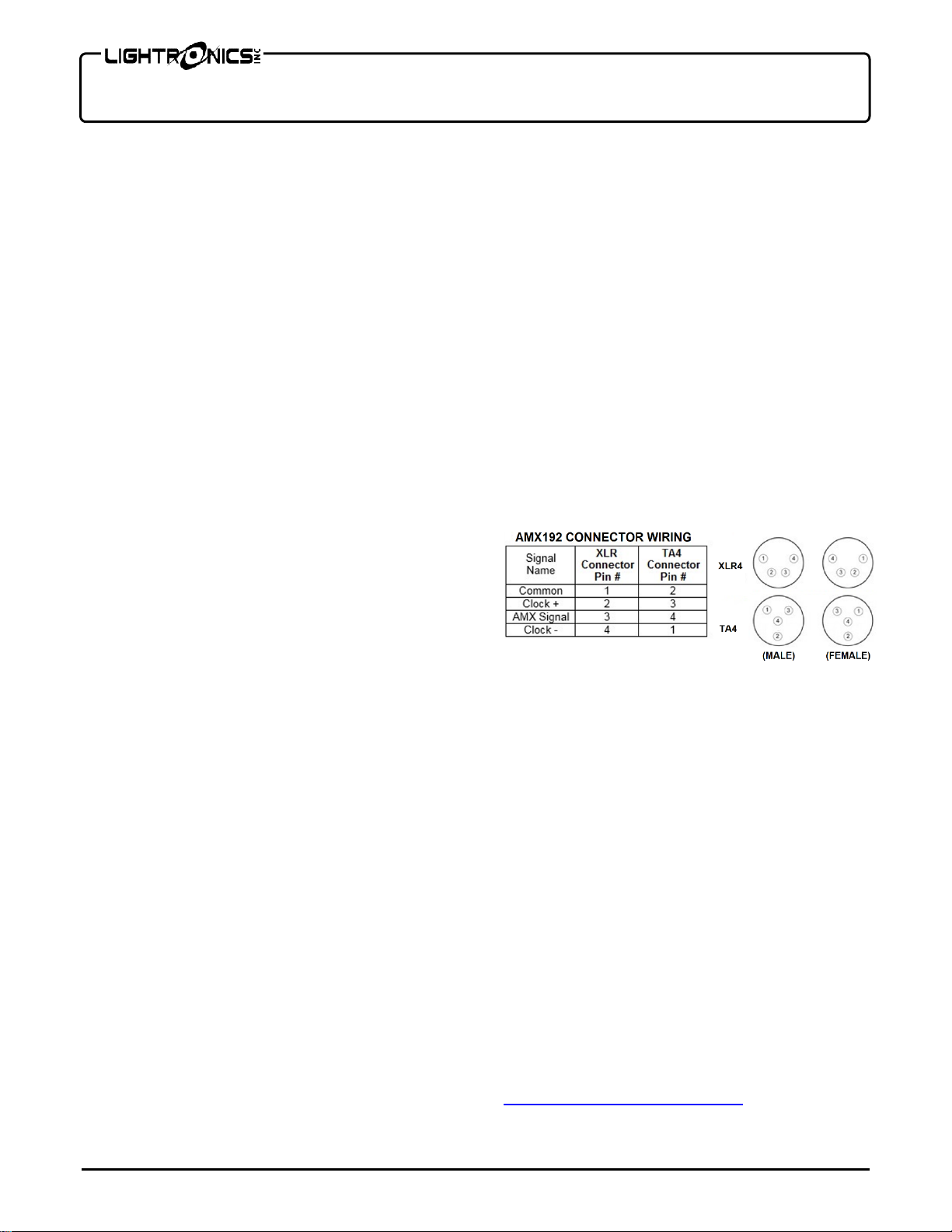
TX192 OPTION
The TX30 may be optionally supplied to transmit the
AMX192 protocol. This model transmits both LMX
and AMX simultaneously. An external power supply
is included and is needed with this option. The
AMX-192 output signal is transmitted from a 4 pin,
male, XLR connector located at the rear of the unit.
CAUTION: Some AMX dimmers use a 4 pin TA4
mini connector for the control signal. This connector
is NOT wired the same as the 4 pin XLR connector.
The following table provides the information needed
to make an adapter cable.
MAINTENANCE AND REPAIR
TROUBLESHOOTING
Verify cables and wiring (a very common
source of problems).
Ensure that all system units are powered on -
particularly the dimmer to which the translator is
connected.
Check address settings at dimmers, console,
and translator. Check console patch configuration.
REPAIR
There are no user serviceable parts in the unit.
Internal service by other than Lightronics authorized
agents will void the warranty. If service is required,
contact the dealer from whom you purchased the
unit or contact the Lightronics Service Dept.
WARRANTY INFORMATION AND
REGISTRATION – CLICK LINK BELOW
www.lightronics.com/warranty.html