Lightware SF11 User manual

SF11
SF11
Laser altimeter Product manual
SF11 Laser Altimeter - Product Manual - Revision 6 of © LightWare Optoelectronics (Pty) Ltd, 20161 20
The SF11 is a compact, lightweight
laser altimeter for above-ground-
level measurement from small fixed
wing or multi-rotor craft.
The SF11 laser altimeter is ideal for
automated landings, precision
hovering and terrain following.
The SF11 is directly compatible with
the Pixhawk and other flight
controllers.
The SF11 laser altimeter makes
accurate distance measurements to
solid surfaces up to an altitude of 120
meters and water up to 40 meters.
Features:
•Very compact and lightweight - 35 grams.
•Accurate AGL altitude measurements on ground,
foliage and water.
•Fast update rate of 20 readings per second.
•Includes serial, I2C, USB and analog interfaces
with programmable capabilities.
•Easy to configure using the built-in menu and
LightWare Terminal software.
•Fully calibrated and ready to run.
•Compatible with Pixhawk, APM and other flight
controllers.
•Accurate, reliable altitude measurements in
sunlight or dark conditions.
•Not affected by: speed; wind; changes in
barometric pressure; noise; ambient light; terrain
or air temperature.

SF11
SF11
Laser altimeter Product manual
Table of contents
Table of figures
Figure 1 :: The main features of the SF11 3................................................................................................................
Figure 2 :: Power from the USB port 5.....................................................................................................................
Figure 3 :: Regulated +5 V DC power supply connections 5..............................................................................................
Figure 4 :: USB communications 5...........................................................................................................................
Figure 5 :: Analog voltage connections 6...................................................................................................................
Figure 6 :: Serial interface connections 6..................................................................................................................
Figure 7 :: I2C interface connections 7.....................................................................................................................
Figure 8 :: LightWare Terminal showing menu options expanded 8....................................................................................
Figure 9 :: Altitude represented by distance (Serial / I2C) and analog voltage 10...................................................................
Figure 10 :: Alarm settings 11................................................................................................................................
Figure 11 :: Median Filter Response graph 13.............................................................................................................
Figure 12 :: Labelling on the SF11 14........................................................................................................................
Figure 13 :: Dimension drawings of the SF11 15...........................................................................................................
Product ordering codes
Disclaimer
Information found in this document is used entirely at the reader’s own risk and whilst every effort has been made to
ensure its validity neither LightWare Optoelectronics (Pty) Ltd nor its representatives make any warranties with respect the
accuracy of the information contained herein.
Product ordering codes 2.....................................................................................................................................
1. Overview 3...................................................................................................................................................
2. Quick start guide 4.........................................................................................................................................
3. Making connections to the SF11 5........................................................................................................................
4. Menu options 8..............................................................................................................................................
5. Instructions for safe use 14...............................................................................................................................
Appendix A :: Specifications 15..............................................................................................................................
Appendix B :: Dimensions 15.................................................................................................................................
Appendix C :: Main cable type 1, 35 cm 16................................................................................................................
Appendix D :: Connecting to Pixhawk Autopilot using “serial 4” 17....................................................................................
Appendix E :: Electromagnetic interference (EMI) graphs 17............................................................................................
Appendix F :: Command set 19...............................................................................................................................
Revision history 20.............................................................................................................................................
Model family Model name Model description
SF11 SF11/C (120 m) Laser altimeter, max 120 m
SF11 Laser Altimeter - Product Manual - Revision 6 of © LightWare Optoelectronics (Pty) Ltd, 20162 20
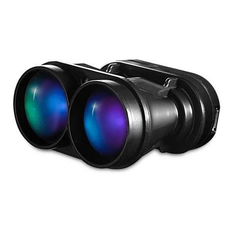
The light-weight, SF11 laser altimeter is an essential addition to any unmanned aircraft that needs fast, accurate and reliable AGL
altitude measurements over solid ground and water.
Operating from a regulated 5 V DC supply, the SF11 includes analog, I2C and serial interfaces that can be easily connected to a
Pixhawk flight controller or other standard processing platform. Each interface on the SF11 can be configured using a simple
software menu that is accessible through the built-in, micro USB port. Settings can also be changed in situ using the command sets
available for the serial and I2C ports.
The SF11 works by measuring the time it takes for a very short flash of laser light to travel to the ground and back again. The
accuracy of the measurement is not affected by the colour or texture of the ground nor the angle of incidence of the laser beam.
The SF11 is virtually immune to background light, wind and noise making it the ideal AGL altimeter for all kinds of terrain.
Figure 1 :: The main features of the SF11
SF11 Laser Altimeter - Product Manual - Revision 6 of © LightWare Optoelectronics (Pty) Ltd, 20163 20

SF11
SF11
Laser altimeter Product manual
2. Quick start guide
1. CAUTION - The SF11 laser altimeter contains a laser and should never be aimed at a
person or an animal. Do not look at the beam directly with optical instruments.
2. Download LightWare Terminal software from www.lightware.co.za > Library >
Documents > Software onto your PC. Open the installer package and follow the
installation instructions. Everything needed for communicating with the SF11 will
automatically be installed.
3. Plug the “micro-B to type A” USB cable provided into the SF11’s micro USB connector
and connect the other end to your PC. This provides both power and communication
to the unit.
4. Start the LightWare Terminal software and click the “Connect” icon to open a
communications port. The distance, analog voltage and signal strength will begin to
scroll in the display window.
5. If the connection isn’t made automatically, click the “Laser” icon and select the
correct USB port from the list shown.
6. Press the <SPACE> key to display the main menu. This menu includes a list of all the
settings that can be changed in the SF11. A summary of the settings is given below:
7. Once you have confirmed your settings, press the <SPACE> key to start taking measurements and the results will be
shown in the Terminal display window.
8. Press the “Disconnect” icon before unplugging the USB cable.
9. There are several embedded interface options available on the main connector. These connections are used to integrate
the SF11 into your system and the details are explained later in this document.
Setting Range of values Description
a: Hide / Show system menu
b: Zero datum offset -10.00 m … +10.00 m Adjusts the zero point from which measurements are taken.
c: Measuring mode long range | quick response Optimises the measuring to suit either long measurements or a
quicker response when signals go out of range.
d: Hide / Show communication menu
e: Serial port baud rate 9600 … 115200 Sets the baud rate for the serial port.
f: Serial output mode on demand | continuous Selects whether data on the serial port is transmitted when a
command is sent or continuously.
g: I2C bus address 0 … 7F Sets the I2C address as a 7 bit, hexadecimal number.
h: Hide / Show analog and alarm menu
i:
Linear analog output 0.00 m to 25.00 m = 0.00 V to 2.56 V, or
0.00 m to 25.00 m = 2.56 V to 0.00 V Selects between a linear analog output or an alarm signal. The
analog output can be selected to give increasing or decreasing
voltage with distance. The alarm can be selected to be active
near or active far.
Switching alarm output <25.00 m = ON | >25.00 m = OFF, or
<25.00 m = OFF | >25.00 m = ON
j: Analog distance range 1.00 m … 120.00 m
Sets the distance at which the analog output reaches the
maximum voltage or the alarm output switches.
Alarm distance range
k: Analog voltage range 0.00 V … 2.56 V or
0.00 V … 3.30 V
Selects the maximum output voltage of the analog output or
the alarm signal. The minimum voltage is always 0.00 V.
Alarm voltage range
l: Alarm hysteresis 0.00 m ... 5.00 m
Sets the hysteresis of the alarm switch point. This setting is
only used when the alarm is active.
m: Hide / Show filter menu
n: Output on lost signal 130.00 m | hold last result Selects the response to a lost signal condition. Either the result
is shown as an out-of-range distance or the last result is held.
p: Confirm lost signal 0.0 ... 120.0 seconds
Sets how long the signal may be lost before the lost signal
condition specified in setting n: is output.
q: Median filter ON / OFF Enables the Median smoothing filter.
r: Median filter size 3 … 32 results Sets how many results are included in the Median filter array.
SF11 Laser Altimeter - Product Manual - Revision 6 of © LightWare Optoelectronics (Pty) Ltd, 20164 20

SF11
SF11
Laser altimeter Product manual
3. Making connections to the SF11
The SF11 gets power from either a regulated +5 V DC supply on the main connector or via the USB port when it is connected to a PC.
There are analog, serial and I2C interfaces on the main connector and either one or a combination of interfaces may be connected to
a host controller. The built-in micro USB port can be used to input settings and to test the performance of the SF11. Settings may
also be changed through the serial and I2C ports.
Power supply option 1: USB
The SF11 can be powered directly from the USB port of a PC or laptop. This is particularly useful for testing the SF11 before it is
installed in your system and also for changing the settings in readiness for the final application.
Figure 2 :: Power from the USB port
Power supply option 2: Regulated +5 V DC
The second power supply option is to connect a regulated voltage of 5 V ± 10% DC to the main connector. If the power wires are more
than 30 cm long, we recommend using a decoupling capacitor of 100 µF, or other noise suppression components to reduce the chance
interference being picked up on the power wires. It is important that this voltage is stable and well regulated.
Figure 3 :: Regulated +5 V DC power supply connections
Communications using the USB port
The SF11 has a micro USB port that can be used to communicate with LightWare Terminal software on a PC. This connection also
provides power to the unit thereby presenting a quick way to test and configure the SF11. The LightWare Terminal software will
automatically detect the USB port that is connected to the SF11 and communications can be established by clicking on the
“Connect” icon. If more than one compatible device is present, click the “Laser” icon to select which USB port should be active.
Once communication has been established, settings can be changed by pressing the <SPACE>
key to access the menu and then
selecting the menu item that needs changing. Pressing the <SPACE>
key again restarts the measuring process. If no settings are
entered then the SF11 automatically restarts after two minutes. More details of the menu items are discussed in the “Menu options”
section below.
If you want to use a different serial emulation program then the USB serial protocol should be set to 115200 baud with 1 stop bit and
no parity or handshaking. All communications are in standard ASCII format.
Figure 4 :: USB communications
SF11 Laser Altimeter - Product Manual - Revision 6 of © LightWare Optoelectronics (Pty) Ltd, 20165 20

SF11
SF11
Laser altimeter Product manual
Analog voltage or alarm interface
The analog or alarm interface on the main connector can be configured to produce either a voltage proportional to the measured
altitude or a high / low alarm signal. The configuration can be changed using menu item <i>.
In analog mode, the maximum distance over which the analog signal is linear can be set using menu item <j>
. This allows for higher
resolution if the SF11 is only used for low level flight. In alarm mode, the same setting is used as the switch point for the alarm.
The voltage scale can be set to deliver a maximum of 2.56 V or 3.3 V depending upon menu selection <k>.
This scale applies to both
the analog and alarm modes of operation.
In alarm mode, menu item <l>
is the hysteresis on the alarm switching distance. This is used to prevent unwanted, rapid switching
when the target is moving around the switching distance. The hysteresis value is symmetrical about the switching point being both
added to and subtracted from the switching point value.
Figure 5 :: Analog voltage connections
Serial interface
The serial interface on the main connector can be used to output the measured altitude in meters as an ASCII encoded number. This
interface uses 3.3 V logic levels (5 V tolerant) and can be connected directly to any similar, compatible interface. Distances are
transmitted whenever the SF11 receives an ASCII ‘d’ character from the host controller. The baud rate for the serial interface is
selectable through the USB menu system. The maximum delay between receiving a character and returning the altitude is 25 ms.
The serial interface also supports an ASCII based command set that can be used to read or write values to the SF11. To read a value,
the command starts with a ‘?’ character and to write a new value, the command starts with a ‘#’ character. All command characters
are in upper case and commands end with the <CR> and <LF> characters (ASCII ‘\r’ and ’\n’).
Commands are echoed back to the host along with the result allowing for totally asynchronous communication with Linux based
controllers. For example, the zero datum offset can be retrieved as follows:
command: ?LO<CR><LF>
reply: ?LO 0.00<CR><LF>
Changing a setting is done in a similar way with the new value appended to the command. The new value is confirmed in the reply.
For example, to change the zero datum offset:
command: #LO,0.32<CR><LF>
reply: #LO,0.32 0.32<CR><LF>
Figure 6 :: Serial interface connections
SF11 Laser Altimeter - Product Manual - Revision 6 of © LightWare Optoelectronics (Pty) Ltd, 20166 20

SF11
SF11
Laser altimeter Product manual
I2C interface
The I2C interface on the main connector can be used to output a value that represents the altitude in centimetres. This interface
operates in “slave” mode and uses 3.3 V logic levels. The I2C address can be set through the USB menu system. The host controller
acts as the I2C “master” and sends the address to the SF11 as an 8 bit value (7 address bits plus 1 read/write bit). The SF11 then
returns the altitude as a 16 bit integer. The maximum delay between receiving the address and returning the altitude is 25 ms.
The I2C bus also has a binary coded command set that can be used to retrieve or change values. Distance values are always in
centimetres and signed values are permitted where used. The main I2C address can only be set through the USB menu and cannot be
change accidentally through the I2C port.
Values in the SF11 are held at specific locations and once a value has been read or written the location remains active until changed.
This is useful to simplify the code needed for the continuous monitoring of a value. For example, to update the distance
continuously, set the distance location once then read the value in a loop like the Arduino code below:
float distance; // Distance will be in meters
byte a, b; // Bytes read by the I2C port
void setup() // One time setup
{
Wire.beginTransmission(0x66); // Enable transmission to the I2C address
Wire.write(0); // Write the distance location -> 0
Wire.endTransmission(); // End the transmission
} // The output registers are now configured to send the distance
void loop() // Main loop
{
delay(50); // Delay or user code here
Wire.requestFrom(0x66, 2); // Request 2 bytes from the SF11
while(Wire.available()) // Make sure the SF11 sends the required number of bytes
{
a = Wire.read(); // Fetch the high byte of the distance
b = Wire.read(); // Fetch the low byte of the distance
}
distance = (float)(a * 256 + b)/100; // Convert to a floating point value in meters
}
Writing new values also makes the new location active so it needs to be changed back again if you want to monitor something else.
In this example the zero datum offset value is updated then the distance is read continuously:
float zero_offset = 0.34; // Start with a new zero datum value in meters
a = (byte)(zero_offset * 100 >> 8); // Convert to cm and fetch the high byte
b = (byte)(zero_offset * 100 && 0xff); // Fetch the low byte
void setup() // One time setup
{
Wire.beginTransmission(0x66); // Enable transmission to the I2C address
Wire.write(7); // Write the zero datum offset location -> 7
Wire.write(a); // Write the high byte of the zero datum
Wire.write(b); // Write the low byte of the zero datum
Wire.endTransmission(); // End the transmission
// The zero datum location is still active but is not needed
Wire.beginTransmission(0x66); // Enable transmission to the I2C address
Wire.write(0); // Write the distance location -> 0
Wire.endTransmission(); // End the transmission - the distance location is now active
}
Figure 7 :: I2C interface connections
Caution
Ensure that a unique I2C address is assigned to the SF11/C and that no other devices share this address.
SF11 Laser Altimeter - Product Manual - Revision 6 of © LightWare Optoelectronics (Pty) Ltd, 20167 20

SF11
SF11
Laser altimeter Product manual
4. Menu options
The SF11 can be connected through the on-board USB port to a Terminal emulation program running on a PC. The LightWare Terminal
software is available for download from www.lightware.co.za.
Once the USB connection is made, the Terminal window displays the distance reading from the SF11. The distance, analog voltage or
alarm status and the signal strength are displayed continually in the Terminal window.
Pressing the <SPACE> key stops the measuring process and changes the display to a menu that lists all the available settings and
configuration options. Pressing the <SPACE>
key again restarts the measuring process. If no changes are made, the unit will
automatically begin to measure again after two minutes. Many of the menu items can also be changed using the serial port or I2C
command set.
Figure 8 :: LightWare Terminal showing menu options expanded
a: Show or hide the system menu
Menu item <a> is used to expand or hide the system menu. The settings available in this menu relate the zero datum offset and the
measuring mode required to suit a particular application.
b: Zero datum offset (-10.00 m … +10.00 m)
The point from which altitude measurements are taken can be adjusted using menu item <b>
. The range of values that can be
entered are from -10.00 meters to +10.00 meters and this value is subtracted from the altitude reading before it is made available
on any of the interfaces. The zero datum offset can be used to compensate for the mounting position of the SF11 in the airframe,
where distance readings may best be interpreted from a suitable point on the landing gear, rather than from the front face of the
SF11.
The zero datum offset can also be changed using the serial port or the I2C command set.
Item HMI Type Serial I2C
Zero datum offset in meters menu item <b>
0.56 m
read ?LO<CR><LF> .write(6) .read(a,b)
?LO 0.35<CR><LF> zero = (a*256+b)/100
write
#LO,0.56<CR><LF> .write(7,a,b)
#LO,0.56 0.56<CR><LF> a = (byte)(zero offset*100 >> 8)
b = (byte)(zero_offset*100 & 0xff)
SF11 Laser Altimeter - Product Manual - Revision 6 of © LightWare Optoelectronics (Pty) Ltd, 20168 20

SF11
SF11
Laser altimeter Product manual
c: Measuring mode (long range | quick response)
Menu item <c>
enables optimisation of the measuring mode to suit applications requiring either long range measurements or a quick
response when signals go out of range. The maximum measuring range remains the same and in many applications there will be little
difference in the performance. However, long range mode is recommended when measuring over water or continually operating at
an altitude above 50 meters. The measuring mode can be also changed using the serial port or the I2C command set.
d: Show or hide the communication menu
Menu item <d>
is used to expand or hide the communication menu. The settings available in this menu relate to the serial port and
the I2C port.
e: Serial port baud rate (9600 … 115200)
The serial port communicates using ASCII encoded data. The baud rate of transmission is selected by menu item <e>
and toggles
through the standard baud rates from 9600 to 115200. There are 8 data bits, 1 stop bit and no parity or handshaking.
The baud rate
cannot be change using the serial port or I2C commands.
f: Serial output mode (on demand | continuous)
Menu item <f> is used to
select whether the distance results on the serial port will become available when a command is sent or
continuously.
In “on demand” mode the distance readings are transmitted when a ‘d’, ‘D’ or ‘\n’ character is received or the specific
?LD<CR><LF> command is used. In continuous mode, the distance is transmitted all the time but other settings and values can still be
accessed using the associated serial port commands. The serial port output mode can be changed using the serial port command set
but cannot be changed using the I2C commands.
g: I2C bus address (0x00 … 0x7F)
The I2C bus operates in slave mode and accepts a 7 bit address (7 address bits plus 1 read bit) before responding with a 16 bit,
binary coded integer. The address can be set by selecting menu item <g> and is entered as a 7 bit, hexadecimal number. The I2C bus
address cannot be changed using the serial port or I2C commands.
h: Show or hide the analog and alarm menu
Menu item <h> is used to expand or hide the analog and alarm menu. The settings available in this menu relate
to the linear analog
voltage output and the alarm.
Item HMI Type Serial I2C
Measuring mode menu item <c>
long range
read ?LM<CR><LF> .write(8) .read(a)
?LM 1<CR><LF> mode = a
write #LM,1 .write(9, a)
#LM,1 1<CR><LF> a = 0 or 1
Item HMI Type Serial I2C
Serial port output type menu item <f>
on demand ... continuous
read ?SU<CR><LF>
?SU 0<CR><LF>
read #SU,0<CR><LF>
#SU,0 0<CR><LF>
SF11 Laser Altimeter - Product Manual - Revision 6 of © LightWare Optoelectronics (Pty) Ltd, 20169 20

SF11
SF11
Laser altimeter Product manual
i: Linear analog output (0.00 m to 25.00 m = 0.00 V to 2.56 V | 0.00 m to 25.00 m = 2.56 V to 0.00 V)
Menu item <i>
is used to select either an analog voltage or a digital alarm output. There are four selections, two for the analog
voltage and two for the alarm. This section describes the analog voltage output. This value may also be changed using the serial port
and I2C command set.
The two analog output selections determine the polarity of the analog voltage. This voltage can be configured to increase with
increasing distance or decrease with increasing distance. The increasing voltage option is useful for measuring the height above
ground whilst the decreasing voltage option might be used to measure the clearance to a roof above the UAV.
Figure 9 :: Altitude represented by distance (Serial / I2C) and analog voltage
j: Analog distance range (1.00 m … 120.00 m)
The distance at which the analog output reaches the maximum voltage can be set by selecting menu item <j>
. The output voltage
can be converted back into a distance by using the formula:
d = v / g * j
where:
d = calculated distance
v = voltage measured by the ADC of the host controller
g = 2.56 V or 3.3 V scale set by menu item h.
j = the maximum distance setting entered using menu item j.
The analog voltage output updates 20 times per second and has a 12 bit resolution. For greatest accuracy, keep the distance range to
the lowest useful value for your application. Do not use the entire measuring range if it is not needed. This value may also
be
changed using the serial port and I2C command set.
Item HMI Type Serial I2C
Analog output mode menu item <i>
analog ... alarm
read ?OM<CR><LF> .write(16) .read(a)
?OM 3<CR><LF> mode = a
write #OM,3<CR><LF> .write(17, a)
#OM,3 3<CR><LF> a = 0, 1, 2 or 3
SF11 Laser Altimeter - Product Manual - Revision 6 of © LightWare Optoelectronics (Pty) Ltd, 201610 20

SF11
SF11
Laser altimeter Product manual
k: Analog voltage range (0.00 V … 2.56 V or 0.00 V … 3.30 V)
Select the maximum voltage of the analog output using menu item <k>
. This provides compatibility with different ADC systems on
the host controller. The analog voltage range may also be changed using the serial port and I2C command set.
i: Switching alarm output (<25.00 m = ON | >25.00 m = OFF | <25.00 m = OFF | >25.00 m = ON)
Menu item <i>
is used to select either an analog voltage or a digital alarm output. There are four selections, two for the analog
voltage and two for the alarm. This section describes the alarm output. This value may also be changed using the serial port and I2C
command set.
Menu item <i> is used to select whether the alarm signal is active near or active far.
An active alarm produces a digital ‘1’ state
whilst no alarm is represented by a digital ‘0’ state. The alarm switching point, output voltage range and the hysteresis can also be
configured as described in the following sections.
Figure 10 :: Alarm settings
Item HMI Type Serial I2C
Analog range / alarm set point menu item <j>
56.78 m
read ?OD<CR><LF> .write(12) .read(a,b)
?OD 56.78<CR><LF> distance range = (a*256+b)/100
write
#OD,56.78<CR><LF> .write(13,a,b)
#OD,56.78 56.78<CR><LF> a = (byte)(range*100 >> 8)
b = (byte)(range*100 & 0xff)
Item HMI Type Serial I2C
Analog voltage range menu item <k>
0.00 V ... 2.56 V
read ?OV<CR><LF> .write(14) .read(a,b)
?OV 2.56<CR><LF> voltage range = (a*256+b)/100
write #OV,0<CR><LF> .write(15,a)
#OV,0 0<CR><LF> a = 0 or 1
SF11 Laser Altimeter - Product Manual - Revision 6 of © LightWare Optoelectronics (Pty) Ltd, 201611 20

SF11
SF11
Laser altimeter Product manual
j: Alarm switching distance (1.00 m … 120.00 m)
The distance at which the alarm output switches can be set by selecting menu item <j>
. This value may also be changed using the
serial port and I2C command set.
k: Alarm voltage range (0.00 V … 2.56 V or 0.00 V … 3.30 V)
Select the logic level output voltage of the alarm signal using menu item <k>
. This provides compatibility with different host
controllers. This value may also be changed using the serial port and I2C command set.
l: Alarm hysteresis (0.00 m … 5.00 m)
The alarm hysteresis stabilises the alarm output when slow moving targets remain near the switching distance for some time. Under
these conditions the alarm may switch many times in succession which may cause problems for the host controller. The hysteresis
moves the set point distance slightly to prevent this from happening. Hysteresis values are symmetrical so a value of 0.3 meters will
decrease the switching distance by 0.3 meters when the ground is far away and increase the switching distance by 0.3 meters when
the ground is close. The alarm hysteresis can also be changed using the serial port and I2C command set.
m: Show or hide the filter menu
Menu item <m>
is used to expand or hide the numerical filter menu. The settings available in this menu relate to providing smoothed
data to all the output ports and rejecting momentary changes in altitude caused by trees, fences, lost signals and out of range
conditions.
n: Output on lost signal (130.00 m | hold last result)
Menu item <n>
is used to select the response to a lost signal condition. Either the result is shown as an out-of-range distance or the
last result is kept. This setting can also be changed using the serial port or I2C command set.
p: Confirm lost signal (0.0 ... 120.0 seconds)
Menu item <p>
is used to set how long a lost signal is permitted before the out of range condition selected in menu item n: is
applied. When operating close to the measuring limit of of the SF11 or over water, signals may be lost intermittently. Rather than
jumping between the measured altitude and the out of range condition, this menu item can be set to hold the last valid altitude for
the entered time. If the lost signal persists for longer than this time then the out of range condition is applied.
The lost signal time
can also be changed using the serial port or I2C command set.
Item HMI Type Serial I2C
Analog range / alarm set point menu item <j>
56.78 m
read ?OD<CR><LF> .write(12) .read(a,b)
?OD 56.78<CR><LF> distance range = (a*256+b)/100
write
#OD,56.78<CR><LF> .write(13,a,b)
#OD,56.78 56.78<CR><LF> a = (byte)(range*100 >> 8)
b = (byte)(range*100 & 0xff)
Item HMI Type Serial I2C
Analog voltage range menu item <k>
0.00 V ... 2.56 V
read ?OV<CR><LF> .write(14) .read(a,b)
?OV 2.56<CR><LF> voltage range = (a*256+b)/100
write #OV,0<CR><LF> .write(15,a)
#OV,0 0<CR><LF> a = 0 or 1
Item HMI Type Serial I2C
Alarm hysteresis menu item <l>
0.03 m
read ?OH<CR><LF> .write(18) .read(a,b)
?OH 0.03<CR><LF> hysteresis = (a*256+b)/100
write
#OH,0.03<CR><LF> .write(19,a,b)
#OH,0.03 0.03<CR><LF> a = (byte)(hysteresis*100 >> 8)
b = (byte)(hysteresis*100 & 0xff)
Item HMI Type Serial I2C
Output on lost signal menu item <n>
last ... 130 m
read ?FL<CR><LF> .write(20) .read(a)
?FL 0<CR><LF> output = a
write #FL,0<CR><LF> .write(21, a)
#FL,0 0<CR><LF> a = 0 or 1
SF11 Laser Altimeter - Product Manual - Revision 6 of © LightWare Optoelectronics (Pty) Ltd, 201612 20

SF11
SF11
Laser altimeter Product manual
q: Enable or disable the median filter menu (ON / OFF)
Menu item <q>
is used to enable the median filter that can be used to reject transient changes in altitude caused by rough terrain,
bushes, fences, ditches or other small obstacles. This improves flight stability during automatic terrain following. The median filter
can also be enabled or disabled using the serial port or I2C command set.
Figure 11 :: Median Filter Response graph
r: Median filter size (3 … 32 results)
Menu item <r> sets the number of readings that are used by the median filter array.
A bigger array will ignore unwanted objects for a
longer time.
The median filter size can also be changed using the serial port or I2C command set.
Item HMI Type Serial I2C
Lost signal timeout menu item <p>
0 ... 120 sec
read ?FC<CR><LF> .write(22) .read(a,b)
?FC 1<CR><LF> timeout = (a*256+b)/100
write
#FC,1<CR><LF> .write(23,a,b)
#FC,1 1<CR><LF> a = (byte)(timeout*100 >> 8)
b = (byte)(timeout*100 & 0xff)
Item HMI Type Serial I2C
Median filter enable menu item <q>
off ... on
read ?FM<CR><LF> .write(24) .read(a)
?FM 1<CR><LF> enable = a
write #FM,1<CR><LF> .write(25, a)
#FM,1 1<CR><LF> a = 0 or 1
Item HMI Type Serial I2C
Median filter size menu item <r>
3 ... 32
read ?FS<CR><LF> .write(26) .read(a)
?FS 8<CR><LF> size = a
write #FS,8<CR><LF> .write(27, a)
#FS,8 8<CR><LF a = 3 .. 32
SF11 Laser Altimeter - Product Manual - Revision 6 of © LightWare Optoelectronics (Pty) Ltd, 201613 20

SF11
SF11
Laser altimeter Product manual
5. Instructions for safe use
The SF11 is a laser based altimeter that emits ionizing laser radiation. The level of the laser emission is Class 1M which indicates that
the laser beam is safe to look at with the unaided eye but must not be viewed using binoculars or other optical devices at a distance
of less than 15 meters. Notwithstanding the safety rating, avoid looking into the beam and switch the unit off when working in the
area.
CAUTION -- The use of optical instruments with this product will increase eye hazard.
The SF11 should not be disassembled or modified in any way. The laser eye safety rating depends on the mechanical integrity of the
optics and electronics so if these are damaged do not continue using the SF11. There are no user serviceable parts and maintenance
or repair must only be carried out by the manufacturer or a qualified service agent.
No regular maintenance is required for the SF11 but if the lenses start to collect dust then they may be wiped with suitable lens
cleaning materials. Make sure that the SF11 is switched OFF before looking into the lenses.
The SF11 should be mounted using the four holes provided in the circuit board. Do not hold or clamp the lens tubes as this may cause
damage and adversely affect the laser safety rating.
Laser radiation information and labels
Figure 12 :: Labelling on the SF11
Specification Value / AEL Notes
Laser wavelength 905 nm
Pulse width < 20 ns
Pulse frequency < 36 kHz
Peak power < 10 W 50 millimeter aperture at 2 meters
Average power < 0.6 mW 7 millimeter aperture
Average energy per pulse < 300 nj
NOHD 15 m Distance beyond which binoculars with may be used safely
SF11 Laser Altimeter - Product Manual - Revision 6 of © LightWare Optoelectronics (Pty) Ltd, 201614 20

SF11
SF11
Laser altimeter Product manual
Appendix A :: Specifications
Appendix B :: Dimensions
Figure 13 :: Dimension drawings of the SF11
SF11/C (120 m)
Range 0.1 … 120 meters (natural targets), 2 ... 40 meters (moving water)
Resolution 1 centimeter
Update rate 20 readings per second
Accuracy ±0.1 meter (70% reflective target @ 20°C)
Power supply voltage 5.0 V ± 0.5 V DC
Power supply current 200 mA (maximum)
Outputs & interfaces Serial, I2C (up to 400 kHz) & analog with maximum latency of 65 ms
Dimensions 30 x 56.5 x 50 millimeters
Weight 35 grams (excluding cables)
Connections Plug & socket, micro USB
Laser power 20 W (peak), <15 mW (average), Class 1M
Optical aperture 51 millimeters
Beam divergence 0.2°
Operating temp. 0 ... 40°C
Approvals FDA: 1630995-000 (2016/09)
SF11 Laser Altimeter - Product Manual - Revision 6 of © LightWare Optoelectronics (Pty) Ltd, 201615 20

SF11
SF11
Laser altimeter Product manual
Appendix C :: Main cable type 1, 35 cm
SF11 Laser Altimeter - Product Manual - Revision 6 of © LightWare Optoelectronics (Pty) Ltd, 201616 20

SF11
SF11
Laser altimeter Product manual
Appendix D :: Connecting to Pixhawk Autopilot using “serial 4”
Appendix E :: Electromagnetic interference (EMI) graphs
The SF11 family has been tested for radio frequency interference in accordance with MIL-STD-451C. The results are well within the
required limits so that neither direct radiation nor secondary radiation from wiring should cause interference to on-board systems
such as GPS and optical flow.
1. 14 kHz to 1 GHz - narrowband
SF11 Laser Altimeter - Product Manual - Revision 6 of © LightWare Optoelectronics (Pty) Ltd, 201617 20

SF11
SF11
Laser altimeter Product manual
2. 14 kHz to 1 GHz - broadband
3. 1 GHz to 10 GHz - narrowband
SF11 Laser Altimeter - Product Manual - Revision 6 of © LightWare Optoelectronics (Pty) Ltd, 201618 20

SF11
SF11
Laser altimeter Product manual
Appendix F :: Command set
Item HMI Type Serial I2C
Model no. and firmware revision menu heading
SF11/C Rev 1.2 read only ?<CR><LF> .write(‘?') .read(a, b)
? SF11/C Rev 1.2<CR><LF> revision = (a*256+b)/100
Distance in meters measuring screen
98.67 m
read only ?LD<CR><LF> .write(0) .read(a, b)
?LD 98.67<CR><LF> distance = (a*256+b)/100
legacy support d’ or ‘D’ or ‘\n’ .write(-1) .read(a, b)
98.67<CR><LF> distance = (a*256+b)/100
Analog output voltage measuring screen
1.567 V read only ?OA<CR><LF> .write(10) .read(a,b)
?OA 1.567<CR><LF> voltage = (a*256+b)/100
Signal strength in % measuring screen
100% read only ?LH<CR><LF> .write(2) .read(a,b)
?LH 100.0<CR><LF> strength = (a*256+b)/100
Zero datum offset in meters menu item <b>
0.56 m
read ?LO<CR><LF> .write(6) .read(a,b)
?LO 0.35<CR><LF> zero = (a*256+b)/100
write
#LO,0.56<CR><LF> .write(7,a,b)
#LO,0.56 0.56<CR><LF> a = (byte)(zero offset*100 >> 8)
b = (byte)(zero_offset*100 & 0xff)
Measuring mode menu item <c>
long range
read ?LM<CR><LF> .write(8) .read(a)
?LM 1<CR><LF> mode = a
write #LM,1 .write(9, a)
#LM,1 1<CR><LF> a = 0 or 1
Serial port output type menu item <f>
on demand ... continuous
read ?SU<CR><LF>
?SU 0<CR><LF>
read #SU,0<CR><LF>
#SU,0 0<CR><LF>
Analog output mode menu item <i>
analog ... alarm
read ?OM<CR><LF> .write(16) .read(a)
?OM 3<CR><LF> mode = a
write #OM,3<CR><LF> .write(17, a)
#OM,3 3<CR><LF> a = 0, 1, 2 or 3
Analog range / alarm set point menu item <j>
56.78 m
read ?OD<CR><LF> .write(12) .read(a,b)
?OD 56.78<CR><LF> distance range = (a*256+b)/100
write
#OD,56.78<CR><LF> .write(13,a,b)
#OD,56.78 56.78<CR><LF> a = (byte)(range*100 >> 8)
b = (byte)(range*100 & 0xff)
Analog voltage range menu item <k>
0.00 V ... 2.56 V
read ?OV<CR><LF> .write(14) .read(a,b)
?OV 2.56<CR><LF> voltage range = (a*256+b)/100
write #OV,0<CR><LF> .write(15,a)
#OV,0 0<CR><LF> a = 0 or 1
Alarm hysteresis menu item <l>
0.03 m
read ?OH<CR><LF> .write(18) .read(a,b)
?OH 0.03<CR><LF> hysteresis = (a*256+b)/100
write
#OH,0.03<CR><LF> .write(19,a,b)
#OH,0.03 0.03<CR><LF> a = (byte)(hysteresis*100 >> 8)
b = (byte)(hysteresis*100 & 0xff)
Output on lost signal menu item <n>
last ... 130 m
read ?FL<CR><LF> .write(20) .read(a)
?FL 0<CR><LF> output = a
write #FL,0<CR><LF> .write(21, a)
#FL,0 0<CR><LF> a = 0 or 1
Lost signal timeout menu item <p>
0 ... 120 sec
read ?FC<CR><LF> .write(22) .read(a,b)
?FC 1<CR><LF> timeout = (a*256+b)/100
write
#FC,1<CR><LF> .write(23,a,b)
#FC,1 1<CR><LF> a = (byte)(timeout*100 >> 8)
b = (byte)(timeout*100 & 0xff)
Median filter enable menu item <q>
off ... on
read ?FM<CR><LF> .write(24) .read(a)
?FM 1<CR><LF> enable = a
write #FM,1<CR><LF> .write(25, a)
#FM,1 1<CR><LF> a = 0 or 1
Median filter size menu item <r>
3 ... 32
read ?FS<CR><LF> .write(26) .read(a)
?FS 8<CR><LF> size = a
write #FS,8<CR><LF> .write(27, a)
#FS,8 8<CR><LF a = 3 .. 32
System noise in mV read only ?LN<CR><LF> .write(28) .read(a,b)
?LN 4.5<CR><LF> noise = (a*256+b)/100
Laser control
read ?LF .write(4) .read(a)
?LF 1<CR><LF> laser control = a
write #LF,1<CR><LF> .write(5,a)
#LF,1 1<CR><LF> a = laser control
SF11 Laser Altimeter - Product Manual - Revision 6 of © LightWare Optoelectronics (Pty) Ltd, 201619 20

SF11
SF11
Laser altimeter Product manual
Revision history
Version Date Authors Comments
Rev 6 2016/09/14 TLP Updated FDA accession number “1630995-000 (2016/09)” in “Appendix A :: Specifications” (page
15).
Rev 5 2016/06/06 TLP Updates to this document revision are applicable from SF11/* firmware revision 1.21,
SN: S11-10345 and S11-10351 onwards. Change of default I2C address from 0x55 to 0x66 to
improve compatibility with PixHawk (page 7). Include the the caution “Ensure that a unique I2C
address is assigned to the SF11/C and that no other devices share this address” (page 7).
Rev 4 2016/05/19 TLP Updates to this document revision are applicable from SF11/* firmware revision 1.2,
SN: S11-10171, SN: S11-10186, SN: S11-10210, SN: S11-10215, and SN: S11-10230 onwards.
Updated “2. Quick start guide” (page 4) and “4. Menu options” (page 8) to reflect new menu
structure. Increase update rate from 16 to 20 readings per second (pages 1, 15). Removed the
“Adaptive filter” menu and graph as this functionality has been replaced with a permanent
smoothing filter. Removed menu “l: Confirm recovered signal” as restart validation is no longer
necessary as there is no chance of noise. Added a new menu “c: Measuring mode” with
selections of “long range” or “quick response” (pages 8, 9). Added a new menu “f: Serial output
mode” with selections of “on demand” or “continuous” (pages 8, 9). Added a new menu “g: I2C
bus address” (pages 8, 9). Added a new menu “l: Alarm hysteresis” (pages 8, 12). Included
“Appendix F :: Command set” (page 19).
Rev 3 2016/03/07 TLP Update I2C feature “up to 400 kHz” in “Appendix A :: Specifications” (page 12).
Rev 2 2016/02/02 TLP Updates to this document revision are applicable from SF11/* SN: S11-00898, firmware
revision 1.1. Update software menu “e: Show the analog output menu” to “e: Show analog and
alarm menu” (pages 4, 8. figure 8). Update software menu “f: Analog distance range” to “f:
Active distance range” (pages 4, 8). Update software menu “g: Linear analog output” to “g:
Output voltage range” (pages 4, 9). Update software menu “h: Analog polarity” to “h: Linear
analog output | h: Switching alarm output” (pages 4, 9).
Rev 1 2016/01/29 TLP Update minimum range on natural targets to “0.1” in “Appendix A :: Specifications” (page 12).
Update FDA accession number “1410968-002 (2016/01)” in “Appendix A :: Specifications” (page
12).
Rev 0 2015/11/13 JEP First edition
SF11 Laser Altimeter - Product Manual - Revision 6 of © LightWare Optoelectronics (Pty) Ltd, 201620 20
Table of contents
Other Lightware Measuring Instrument manuals

Lightware
Lightware SF02/F User manual

Lightware
Lightware SF30/B User manual

Lightware
Lightware SF10 User manual

Lightware
Lightware SF10 User manual

Lightware
Lightware SF40/C User manual

Lightware
Lightware SF11/C User manual

Lightware
Lightware SF30/B User manual

Lightware
Lightware SF33 User manual

Lightware
Lightware SF02 User manual