Lightware SF02 User manual

SF02
SF02
Laser rangefinder Product manual
!
!
!
!
!
!
!
!
!
!
!
!
!
!
!
!
!
SF02 Laser Rangefinder - Product Manual - Revision 4 !of !© LightWare Optoelectronics (Pty) Ltd, 2013114
The SF02 is a lightweight laser
rangefinder module that provides fast
and accurate distance measurements.
!
The module comprises all the
necessary optical and electronic
components along with embedded
software for a pulsed laser, time-of-
flight, distance measuring
instrument.
!
Its configurable features and
standard hardware interfaces make
the SF02 an easy to understand
module that can be used in
unmanned aerial vehicles (UAV),
radio-controlled aircraft and robots.
Features:
!
•A laser-based rangefinder module suitable for
many applications.!
!
•Accurately measures the distance to natural
surfaces and objects.!
!
•Can detect surfaces and objects up to a distance
of 40 meters.!
!
•Measures distance at 12 readings per second.!
!
•Includes digital and analog interfaces with
programmable capabilities.!
!
•Easy to configure using the built-in menus and
LightWare’s Terminal software.!
!
•Fully calibrated and ready to run.!
!
•Affordable for the student or hobbyist.!
!
•Robust and reliable.!
!
•Not affected by: wind; changes in barometric
pressure; noise; ambient light; terrain or air
temperature.!

SF02
SF02
Laser rangefinder Product manual
!
!
Tab le o f co nt en ts
!
!
!
Table of figures
!
Figure 1 :: The main features of the SF02 4...............................................................................................................
Figure 2 :: Power from the USB port 5......................................................................................................................
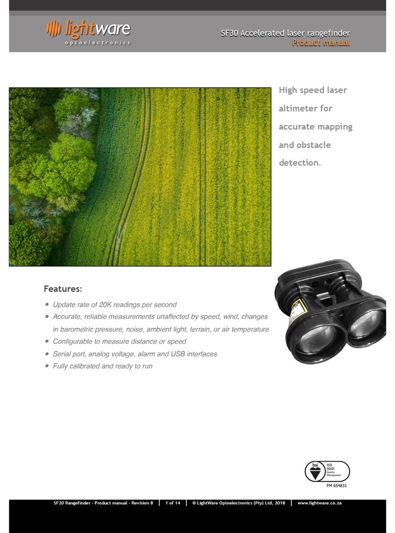
Figure 3 :: Battery power 5...................................................................................................................................
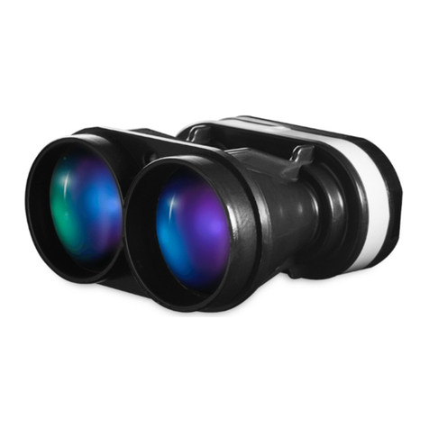
Figure 4 :: Regulated 5V DC supply 6.......................................................................................................................
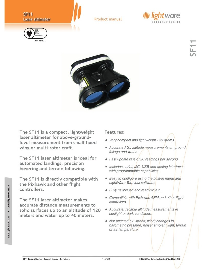
Figure 5 :: Dual redundant power supplies 6..............................................................................................................
Figure 6 :: USB communications 7...........................................................................................................................
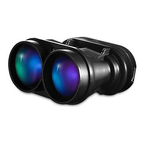
Figure 7 :: Analog interface, Analog voltage output 7...................................................................................................
Figure 8 :: Digital interface, Digital alarm output 7.....................................................................................................
Figure 9 :: Serial interface, Auxiliary serial port basic connection 8..................................................................................
Figure 10 :: Serial interface, Auxiliary serial port with hardware trigger 8.........................................................................
Figure 11 :: LightWare Terminal showing menu options 9...............................................................................................

Figure 12 :: Height above ground represented by the analog voltage output 10....................................................................
Figure 13 :: Ground proximity alarm warning 10.........................................................................................................
Figure 14 :: Measuring speed 11.............................................................................................................................
Figure 15 :: Compensating for the height of the landing gear 11......................................................................................
Figure 16 :: Labeling on the SF02 12........................................................................................................................
Figure 17 :: Accuracy profile 13..............................................................................................................................
Figure 18 :: Dimension drawings of the SF02 14..........................................................................................................
!
!
!
!
!
!
!
!
!
!
!
!
!
!
!
!
!
!
!
!
!
!
!
!
!
!
!
Disclaimer
!
Information found in this document is used entirely at the reader’s own risk and whilst every effort has been made to
ensure its validity neither LightWare Optoelectronics (Pty) Ltd nor its representatives make any warranties with respect the
accuracy of the information contained herein.
!
1. Overview 3...................................................................................................................................................
2. Quick start guide 4..........................................................................................................................................
2. Making connections to the SF02 5........................................................................................................................
3. Menu options 9...............................................................................................................................................
4. Instructions for safe use 12................................................................................................................................
Appendix A :: Specifications 13...............................................................................................................................
Appendix B :: Dimensions 14..................................................................................................................................
Revision history 14..............................................................................................................................................
SF02 Laser Rangefinder - Product Manual - Revision 4 !of !© LightWare Optoelectronics (Pty) Ltd, 2013214

SF02
SF02
Laser rangefinder Product manual
!
!
1. Overview
!
The lightweight, SF02 laser rangefinder module is an essential addition to any system that needs fast, accurate and reliable distance
measurements.
!
Operating from a 9 V battery or a regulated 5 V DC supply, the SF02 includes analog, digital and serial interfaces that can be easily
connected to an embedded controller or a standard processing platform such as Arduino®or Raspberry Pi®. Each interface on the
SF02 can be configured using a simple software menu that is accessible through the built-in USB port.
!
The SF02 works by measuring the time it takes for a very short flash of laser light to travel to an object and back again. The accuracy
of the measurement is not affected by the the color of the object’s surface or the angle of incidence of the laser beam to the
surface. The SF02 is virtually immune to background light, wind, noise and other environmental interference.
!
The maximum measuring range of the SF02 is 40 meters and readings are updated 12 times per second. There is an option to smooth
the distance measurements if higher resolution is required or use the raw results if higher speed is needed.
!
!
!
!
!
Figure 1 :: The main features of the SF02
!
!
!
!
!
!
!
!
!
!
!
!
!
SF02 Laser Rangefinder - Product Manual - Revision 4 !of !© LightWare Optoelectronics (Pty) Ltd, 2013314

SF02
SF02
Laser rangefinder Product manual
!
!
!
2. Quick start guide
!
1. CAUTION - The SF02 laser rangefinder contains a laser and should never be aimed at a
person or an animal. Do not look at the beam directly with optical instruments.
2. Plug a USB cable into the SF02’s mini USB connector and connect the other end into a
PC. This provides both power and communication for the unit.
3. Download LightWare Terminal software from www.lightware.co.za > Library >
Documents > Software onto your PC. Open the installer package and follow the install
instructions and everything needed for communicating with SF02 will automatically be
installed.
4. Start the LightWare Terminal software and click the “Connect” icon to open a
communications port. The distance measurements should begin to scroll in the
Terminal window. If the connection isn’t made automatically then click the “Settings”
icon and select the correct port from the list shown.
5. The configuration menu is accessed by pressing the <SPACE> bar on your keyboard. This
stops the measurements and displays a list of settings along with a brief description of
what each one does. Pressing the <SPACE> bar again restarts measuring.
6. A summary of the settings is given below:
!
!
7. Once you have confirmed your settings, click the “Disconnect” icon and disconnect the USB cable from the SF02.
!
8. There are several power supply and interface options available on the green connector. These connections are used to
integrate the SF02 into your system and details of all the options are explained later in this document.
!
!
!
Section
Setting
Range of values
Description
Analog voltage
output
1. 0.0 V distance
0.00m to 40.00m
Sets the distance at which the voltage output will show 0.0V
2. 3.3 V distance
0.00m to 40.00m
Sets the distance at which the voltage output will show 3.3V
Digital alarm
output
3. Alarm distance
0.00m to 40.00m
Sets the distance at which the alarm will indicate a close object
4. Alarm deadband
0.00m to 1.00m
Creates a deadband between the on and off points of the alarm
Auxiliary UART
5. Baud rate
4800 ... 115200
Selects the baud rate of the auxiliary serial port UART channel
Measuring
6. Speed
Fast or Slow
Selects the speed at which the measurements update
Zero
calibration
7. Zero point
-1.00m to +1.00m
Adjusts the point from which measurements are taken
SF02 Laser Rangefinder - Product Manual - Revision 4 !of !© LightWare Optoelectronics (Pty) Ltd, 2013414

SF02
SF02
Laser rangefinder Product manual
!
!
2. Making connections to the SF02
!
The SF02 has four power supply options and a number of digital and analog interfaces. Only one power supply needs to be connected
for correct operation and any one of the interfaces may be connected to a host controller.
!
!
Power supply option 1: USB
!
The first option is to power the unit directly from the USB port of a PC or laptop. This is particularly useful for testing the SF02
before it is installed in your system and also for changing the settings in readiness for the final application.
!
!
!
!
Figure 2 :: Power from the USB port
!
!
Power supply option 2: Battery
!
The second power supply option is to connect to an unregulated battery with a voltage of 6.5 - 9 V DC between screw terminals 1
and 2. In this configuration a regulated 4.7V DC power output becomes available on screw terminal 3 and this can be used by
external circuitry as a source of regulated power.
!
!
!
!
Figure 3 :: Battery power
!
!
!
!
!
!
!
!
!
!
!
SF02 Laser Rangefinder - Product Manual - Revision 4 !of !© LightWare Optoelectronics (Pty) Ltd, 2013514

SF02
SF02
Laser rangefinder Product manual
!
!
Power supply option 3: Regulated
!
The third power supply option is to use a regulated 5 V supply connected between screw terminals 2 and 3. In this configuration
terminal 1 is not used. The 5 V DC supply would typically be taken from an existing power rail that is used to supply other electronic
equipment.
!
CAUTION: The +5 V power input on screw terminal 3 is not protected from reverse polarity. Damage to the SF02 will result if this
connection is reversed.
!
!
!
!
Figure 4 :: Regulated 5V DC supply
!
!
Power supply option 4: Dual redundancy
!
For high reliability applications, dual redundancy of the power supply can be achieved by connecting both a battery and a regulated
5 V supply. In this configuration, the +5 V must be supplied through a reverse protection diode with a low forward voltage drop. We
recommend using a 1N5819 Schottky diode. Under normal conditions power is drawn from the +5 V supply but if this supply fails then
power will be drawn from the battery.
!
!
!
!
Figure 5 :: Dual redundant power supplies
!
!
!
!
!
!
!
!
!
!
SF02 Laser Rangefinder - Product Manual - Revision 4 !of !© LightWare Optoelectronics (Pty) Ltd, 2013614

SF02
SF02
Laser rangefinder Product manual
!
!
USB interface
!
The SF02 has a mini USB interface that can be used to communicate with LightWare Terminal software on a PC. This connection also
provides power to the unit thereby presenting a quick way to test and configure the SF02. The associated serial port transmits at
115200 baud with 1 stop bit and no parity or handshaking. More details are discussed in the “Menu options” section below.
!
!
!
!
Figure 6 :: USB communications
!
!
Analog voltage output
!
The analog voltage interface on screw terminal 7 produces a linear voltage of between 0.0 V and 3.3 V that is proportional to the
measured distance. The actual distances of the 0.0 V and 3.3 V end points can be adjusted through the menu system. The analog
voltage can be measured by the host controller using any available analog-to-digital-converter (ADC). The voltage is updated 12
times per second and has 10 bit resolution.
!
!
!
!
Figure 7 :: Analog interface, Analog voltage output
!
!
Alarm output
!
The alarm output on screw terminal 6 is a digital warning signal that becomes active when an object is closer than a preset distance.
The alarm distance can be set using the menu system. The alarm is active high with an output of 3.3 V. This alarm signal can be
connected to an available digital port pin on the host controller and read as: low = safe and high = alarm.
!
!
!
!
Figure 8 :: Digital interface, Digital alarm output
!
!
!
!
!
!
!
!
!
!
!
SF02 Laser Rangefinder - Product Manual - Revision 4 !of !© LightWare Optoelectronics (Pty) Ltd, 2013714

SF02
SF02
Laser rangefinder Product manual
!
!
Auxiliary serial port
!
The auxiliary serial port on screw terminals 8 and 9 outputs an ASCII encoded string as a floating point representation of the distance
measured. The serial port uses 0 V / 3.3 V logic and is designed for direct connection to a similar serial port on the host controller.
The baud rate is selectable using the menu system.
!
!
!
!
Figure 9 :: Serial interface, Auxiliary serial port basic connection
!
!
The time when distance data is transmitted from the auxiliary serial port is controlled by one of two triggers. The first is a software
trigger provided by the host controller through its serial port and consists of the ASCII code for the letter <D>. When the SF02
receives this character it outputs the next available distance result which will happen in less than 100 ms.
!
There is an alternative hardware trigger on screw terminal 4 that can be controlled by a digital port pin on the host controller. This
trigger is active low and can be either a negative going pulse or can be held low in order to get a continuous stream of distance data
from the auxiliary serial port.
!
!
!
!
Figure 10 :: Serial interface, Auxiliary serial port with hardware trigger
!
!
!
SF02 Laser Rangefinder - Product Manual - Revision 4 !of !© LightWare Optoelectronics (Pty) Ltd, 2013814

SF02
SF02
Laser rangefinder Product manual
!
!
3. Menu options
!
The SF02 can be connected through the on-board USB port to a Terminal emulation program running on a PC. LightWare provides a
free Terminal program available for download from its website at http://www.lightware.co.za/index.php/lib-docs
!
Once the USB connection is made, the Terminal window displays the distance reading from the SF02. Pressing the <SPACE> bar stops
the measuring process and changes the display to a menu that lists all the available settings and configuration options. Pressing the
<SPACE> bar again restarts the measuring process.
!
!
!
!
Figure 11 :: LightWare Terminal showing menu options
!
!
SF02 Laser Rangefinder - Product Manual - Revision 4 !of !© LightWare Optoelectronics (Pty) Ltd, 2013914

SF02
SF02
Laser rangefinder Product manual
!
!
Analog voltage output settings
!
Menu items <1> and <2> relate to the analog voltage output and are used to set the end point distances that correspond to the 0.0 V
and 3.3 V output voltages. These voltages are read by the ADC of the host controller and can be converted back into a distance by
using the formula:
!
d = v / 3.3 * (DH - DL) + DL
where:
d = measured distance
v = voltage measured by the ADC of the host
DL = 0.0V distance
DH = 3.3V distance
!
The range of values for both distance settings is from 0.00 meters to 40.00 meters. The analog voltage output updates at 12 readings
per second and has a 10 bit resolution.
!
!
!
Figure 12 :: Height above ground represented by the analog voltage output
!
!
Alarm settings
!
The digital alarm output goes high whenever an object is detected that is closer than the distance setting shown in menu item <3>.
This distance can be set from 0.00 meters to 40.00 meters and the alarm output is updated 12 times per second. To prevent multiple
switching of the alarm output, menu item <4> provides for hysteresis on the alarm distance. This will change the alarm activation
and deactivation distances to:
!
activation distance = alarm distance - hysteresis
deactivation distance = alarm distance + hysteresis
!
The hysteresis can be adjusted up to 1.00 meters.
!
!
!
!
Figure 13 :: Ground proximity alarm warning
SF02 Laser Rangefinder - Product Manual - Revision 4 !of !© LightWare Optoelectronics (Pty) Ltd, 201310 14

SF02
SF02
Laser rangefinder Product manual
!
!
Auxiliary serial port (UART)
!
The auxiliary serial port, or UART, transmits a serial string of ASCII encoded data from the SF02 to the host controller. The baud rate
of transmission is selected by menu item <5> and can be any of the standard baud rates from 4800 to 115200. By default, there is
one stop bit and no parity or handshaking on this serial port.
!
The ASCII string representing the distance is in floating point format with two decimal places followed by carriage return and line
feed, as follows:
!
“22.48\r\n”
!
where carriage return and line feed are given by the hexadecimal ASCII characters:
!
\r = 0x0D
\n = 0x0A
!
Data is sent out of the auxiliary serial port whenever a “trigger” notification is received. The ASCII character <D> acts as a trigger
when transmitted by the host controller to the SF02. Additionally, there is an active low, hardware trigger that can be controlled by
a digital port pin on the host controller.
!
!
Measuring speed
!
The measuring speed can be selected by menu item <6> to be either fast or slow. In fast mode the readings update 12 times per
second. In slow mode, a four point rolling average filter is applied to the distance readings giving a smoother output. The slow mode
is for making more precision measurements.
!
!
!
!
Figure 14 :: Measuring speed
!
!
!
Zero point
!
The point from which distance measurements are taken can be adjusted using menu item <7>. The range of values that can be
entered are from -1.00 meters to +1.00 meters. This zero point adjustment can be used to compensate for the mounting position of
the SF02 in the final system, where distance readings may best be interpreted from a suitable point on the system rather than from
the front face of the SF02.
!
!
!
!
Figure 15 :: Compensating for the height of the landing gear
!
!
!
!
!
!
!
!
SF02 Laser Rangefinder - Product Manual - Revision 4 !of !© LightWare Optoelectronics (Pty) Ltd, 201311 14

SF02
SF02
Laser rangefinder Product manual
!
!
4. Instructions for safe use
!
The SF02 is a laser range finder that emits ionizing laser radiation. The level of the laser emission is Class 1M which indicates that
the laser beam is safe to look at with the unaided eye but must not be viewed using binoculars or other optical devices at a distance
of less than 15 meters. Notwithstanding the safety rating, avoid looking into the beam and switch the unit off when working in the
area.
!
CAUTION -- The use of optical instruments with this product will increase eye hazard.
!
The SF02 should not be disassembled or modified in any way. The laser eye safety rating depends on the mechanical integrity of the
optics and electronics so if these are damaged do not continue using the SF02. There are no user serviceable parts and maintenance
or repair must only be carried out by the manufacturer or a qualified service agent.
!
No regular maintenance is required for the SF02 but if the lenses start to collect dust then they may be wiped with suitable lens
cleaning materials. Make sure that the SF02 is switched OFF before looking into the lenses.
!
The SF02 should be mounted using the four holes provided in the circuit board. Do not hold or clamp the lens tubes as this may cause
damage and adversely affect the laser safety rating.
!
!
Laser radiation information and labels
!
!
!
!
!
Figure 16 :: Labeling on the SF02
!
!
!
!
!
Specification
Value / AEL
Notes
Laser wavelength
850 nm
Pulse width
< 30 ns
Pulse frequency
< 16 kHz
Peak power
< 10 W / 15.96 W
50 mm aperture at 2 m
Average power
<0.6 mW / 0.78 mW
7 mm aperture
Average energy per pulse
<0.15 nj / 200 nj
NOHD
<15 m
Distance beyond which binoculars with may be used safely
SF02 Laser Rangefinder - Product Manual - Revision 4 !of !© LightWare Optoelectronics (Pty) Ltd, 201312 14

SF02
SF02
Laser rangefinder Product manual
!
!
Appendix A :: Specifications
!
!
!
!
!
!
!
!
!
Figure 17 :: Accuracy profile
!
!
!
!
Power supply voltage
6.5 V .. 9.0 V or 5.0 V ± 0.5 V DC
Power supply current
150 mA (maximum)
Measuring range
40 m (natural targets)
Resolution
1 cm
Accuracy
See Figure 17 below
Update rate [readings per second]
12 readings per second
Laser power
14 W (peak), 6 mW (average), Class 1M
Weight
75 g (2.65 oz)
Optical module dimensions
54 mm x 27 mm (front face)
Electronic modules dimensions
40 mm (length) x 59 mm (width)
Mounting holes
4 x 3.2 mm holes spaced 32 mm x 52 mm
Operating temperature
0 ... 40°C
Approvals
FDA accession number: 1310953-000 (2013/12)
SF02 Laser Rangefinder - Product Manual - Revision 4 !of !© LightWare Optoelectronics (Pty) Ltd, 201313 14

SF02
SF02
Laser rangefinder Product manual
!
!
Appendix B :: Dimensions !
!
!
!
Figure 18 :: Dimension drawings of the SF02
!
!
!
!
!
!
!
Revision history
!
Version
Date
Authors
Comments
Rev 4
2014/01/05
JEP
Corrected the hexadecimal ASCII characters: \r = 0x0D and \n = 0x0A
(page 11).
Rev 3
2013/12/18
TLP
“Appendix A :: Specifications” (page 13) include “Approvals” information
regarding FDA accession number “1310953-000”
Rev 2
2013/09/30
TLP
“Appendix A :: Specifications” (page 13) corrected “Measuring range” to
read “40 m”.
Rev 1
2013/09/12
TLP
Move section “1. Overview” to page 3. Include “-“ and “+” symbols in
Figures 3, 4 and 5. Update UAV image in Figures 12, 13 and 15.
Rev 0
2013/09/03
JEP
First edition
SF02 Laser Rangefinder - Product Manual - Revision 4 !of !© LightWare Optoelectronics (Pty) Ltd, 201314 14
Table of contents
Other Lightware Measuring Instrument manuals

Lightware
Lightware SF40/C User manual

Lightware
Lightware SF30/B User manual

Lightware
Lightware SF30/B User manual

Lightware
Lightware SF10 User manual

Lightware
Lightware SF11 User manual

Lightware
Lightware SF33 User manual

Lightware
Lightware SF02/F User manual

Lightware
Lightware SF11/C User manual

Lightware
Lightware SF10 User manual
Popular Measuring Instrument manuals by other brands

THORLABS
THORLABS PM100A quick reference

Franklin Electric
Franklin Electric Little Giant CONDALERT LC-110 manual

Lorex
Lorex N863 Series Quick setup guide

J.A. Woollam
J.A. Woollam M-2000 Hardware manual

MADDALENA
MADDALENA ElecTo SONIC Instructions for installation, use and maintenance

Munters
Munters CO2 Sensor installation manual