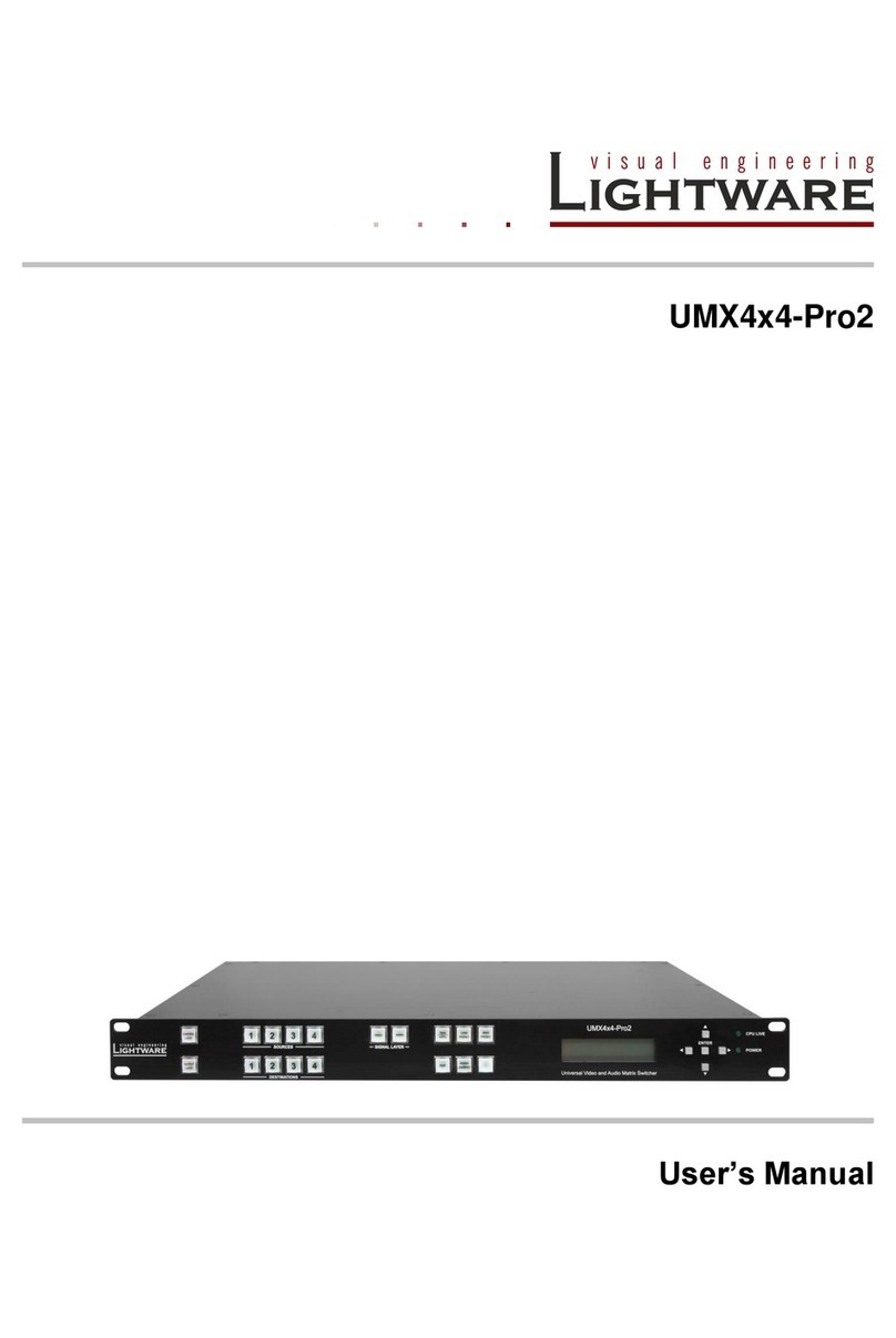
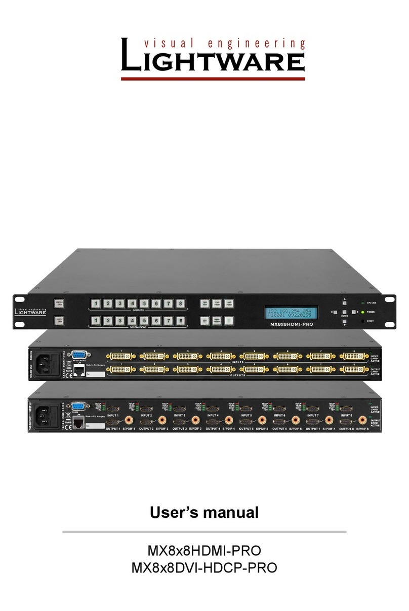
Lightware MX-FR9 User manual

MX-FR9 MX-FR17 MX-FR33L MX-FR33R MX-FR80R
MX-CPU2 board
MX-FR9
MX-FR17
MX-FR33
MX-FR33L
MX-FR33R
MX-FR65R
MX-FR80R
with MX-CPU2
User’s Manual


MX-FR series modular matrices
User’s Manual
Section 1. Introduction Page 3 / 137
SAFETY INSTRUCTIONS
Class I apparatus construction. This equipment must be used with a main power system with a
protective earth connection. The third (earth) pin is a safety feature, do not bypass or disable it.
This equipment should be operated only from the power source indicated on the product.
To disconnect the equipment safely from power, remove the power cord from the rear of the
equipment, or from the power source. The MAINS plug is used as the disconnect device, the
disconnect device shall remain readily operable.
There are no user-serviceable parts inside of the unit. Removal of the top cover will expose
dangerous voltages. To avoid personal injury, do not remove the top cover. Do not operate the unit
without the cover installed.
The apparatus shall not be exposed to dripping or splashing and that no objects filled with liquids,
such as vases, shall be placed on the apparatus.
The apparatus must be safely connected to multimedia systems. Follow instructions described in
this manual.
Replacing the AC fuse
Unplug the AC power cord from the equipment
Locate the AC fuse on the rear of the unit
Replace only the AC fuse as indicated on the rear panel of the unit: 3.15A fast blowing
Connect the power cord to the switcher and to the AC power source. Make sure the
switcher is working properly.
WEEE ( Waste Electrical & Electronic Equipment )
Correct Disposal of This Product
This marking shown on the product or its literature, indicates that it should not be
disposed with other household wastes at the end of its working life. To prevent possible
harm to the environment or human health from uncontrolled waste disposal, please
separate this from other types of wastes and recycle it responsibly to promote the
sustainable reuse of material resources.
Household users should contact either the retailer where they purchased this product, or
their local government office, for details of where and how they can take this item for
environmentally safe recycling.
Business users should contact their supplier and check the terms and conditions of the purchase contract.
This product should not be mixed with other commercial wastes for disposal.

Page 4 / 137 Section 1. Introduction
DECLARATION OF CONFORMITY
We,
Lightware Kft. 1071 Budapest Peterdy str. 15 HUNGARY
as manufacturer declare, that the products
MX-FR9
MX-FR17
MX-FR33
MX-FR33L
MX-FR33R
MX-FR65R
MX-FR80R
( Computer Matrix Switcher )
in accordance with the EMC Directive 2004/108/EC and the Low Voltage Directive
2006/95/EEC are in conformity with the following standards:
EMI/EMC .................... EN 55103-1 E3, EN 55103-2
Safety .......................................... EN 60065 Class I
Date: 16.09.2010.
Name: Gergely Vida ( Managing Director )
Signed:

MX-FR series modular matrices
User’s Manual
Section 1. Introduction Page 5 / 137
Table of contents
1. INTRODUCTION...................................................................................................................... 9
1.1. BOX CONTENTS................................................................................................................... 9
1.2. DESCRIPTION...................................................................................................................... 9
1.3. FEATURES........................................................................................................................ 10
1.4. APPLICATIONS .................................................................................................................. 11
2. HYBRID MODULAR MATRIX CONCEPT............................................................................. 12
2.1. ROUTER FRAMES .............................................................................................................. 12
2.1.1. MX-CPU2 processor board..................................................................................... 12
2.2. MX-CPU2 AS AN UPGRADE FOR OLDER FRAMES ................................................................ 13
2.3. INPUT BOARDS.................................................................................................................. 14
2.4. OUTPUT BOARDS .............................................................................................................. 14
3. CONTROLS AND CONNECTIONS....................................................................................... 16
3.1. MX-FR80R AND MX-FR65R............................................................................................ 16
3.2. MX-FR33R...................................................................................................................... 20
3.3. MX-FR33L ...................................................................................................................... 21
3.4. MX-FR33 ........................................................................................................................ 22
3.5. MX-FR17 ........................................................................................................................ 23
3.6. MX-FR9 .......................................................................................................................... 25
3.7. ELECTRICAL CONNECTIONS ............................................................................................... 26
3.7.1. Power connection ................................................................................................... 26
3.7.2. DVI inputs and outputs............................................................................................ 26
3.7.3. HDMI inputs and outputs ........................................................................................ 27
3.7.4. S/PDIF digital audio input and output..................................................................... 27
3.7.5. Twisted Pair inputs and outputs.............................................................................. 28
3.7.6. RS-232 connectors (available on some I/O boards)............................................... 29
3.7.1. Fiber optical inputs and outputs.............................................................................. 29
3.7.2. 3G-SDI inputs ......................................................................................................... 29
3.7.3. Analog stereo audio input and output connectors .................................................. 30
3.7.4. Symmetrical analog stereo audio ........................................................................... 30
3.7.5. RS-232 / RS-422 control port ................................................................................. 31
3.7.6. Ethernet port ........................................................................................................... 31
3.7.7. Genlock input.......................................................................................................... 32
3.7.8. Alarm output............................................................................................................ 32
4. TECHNOLOGIES................................................................................................................... 33
4.1. UNDERSTANDING EDID..................................................................................................... 33
4.1.1. Basics...................................................................................................................... 33
4.1.2. Common problems related to EDID........................................................................ 33
4.2. ADVANCED EDID MANAGEMENT ........................................................................................ 34
4.3. PIXEL ACCURATE RECLOCKING ......................................................................................... 34
4.4. HDCP MANAGEMENT........................................................................................................ 36
4.4.1. Mixing encrypted and unencrypted signals ............................................................ 36
4.4.2. HDPC key cashing.................................................................................................. 36
4.4.3. Avoiding unnecessary HDCP encryption................................................................ 36
5. OPERATION.......................................................................................................................... 38
5.1. POWERING ON.................................................................................................................. 38
5.2. FRONT PANEL OPERATIONS ............................................................................................... 38
5.2.1. CONTROL LOCK.................................................................................................... 38
5.2.2. TAKE / AUTOTAKE modes.................................................................................... 38
5.2.3. Source and destination buttons .............................................................................. 39
5.2.4. Viewing crosspoint state......................................................................................... 39
5.2.5. Switching................................................................................................................. 40
5.2.6. Switching operations flowchart ............................................................................... 41
5.2.7. Preset operations.................................................................................................... 42
5.2.8. OUTPUT LOCK ...................................................................................................... 42

Page 6 / 137 Section 1. Introduction
5.3. ABOUT EDID MEMORY...................................................................................................... 44
5.3.1. EDID types.............................................................................................................. 44
5.3.2. Factory EDID list..................................................................................................... 45
5.4. FRONT PANEL LCD MENU OPERATION................................................................................ 46
5.4.1. Basic concept.......................................................................................................... 46
5.4.2. Normal mode .......................................................................................................... 47
5.4.3. LCD menu pop-up messages................................................................................. 57
5.4.4. EDID mode ............................................................................................................. 58
5.4.5. Signal Present mode............................................................................................... 59
5.5. REMOTE OPERATION......................................................................................................... 60
5.5.1. Control interfaces.................................................................................................... 60
5.5.2. Multiple simultaneous connections......................................................................... 61
5.5.3. IP settings ............................................................................................................... 61
5.5.4. Serial port settings.................................................................................................. 62
5.5.5. Control protocols..................................................................................................... 62
6. SOFTWARE CONTROL –USING LIGHTWARE MATRIX CONTROLLER ........................ 63
6.1. INSTALLING THE MATRIX CONTROLLER SOFTWARE ............................................................. 63
6.2. ESTABLISHING THE CONNECTION ....................................................................................... 64
6.3. CONTROL MENU................................................................................................................ 66
6.3.1. Navigation............................................................................................................... 66
6.3.2. Input and output board types.................................................................................. 67
6.3.1. Port status display................................................................................................... 67
6.3.2. CPU board DVI ports .............................................................................................. 68
6.3.3. Input and output names.......................................................................................... 69
6.3.4. Quick I/O port information....................................................................................... 69
6.3.5. Crosspoint operations............................................................................................. 69
6.3.6. Preset operations.................................................................................................... 70
6.3.7. Preset names.......................................................................................................... 71
6.3.8. Input parameter settings......................................................................................... 71
6.3.9. Output parameter settings ...................................................................................... 81
6.3.10. Frame detector........................................................................................................ 87
6.3.11. HDCP key counter.................................................................................................. 88
6.4. GENLOCK SETTINGS.......................................................................................................... 89
6.4.1. Locking to video sync.............................................................................................. 89
6.4.2. Locking to TTL signal.............................................................................................. 90
6.4.3. Locking to Preview output DVI................................................................................ 91
6.4.4. Locking to Test input DVI........................................................................................ 91
6.5. EDID MENU...................................................................................................................... 92
6.5.1. EDID Router operation............................................................................................ 92
6.5.2. Advanced EDID Editor............................................................................................ 94
6.5.3. Easy EDID Creator ................................................................................................. 95
6.6. TERMINAL MENU ............................................................................................................... 95
6.7. STATUS MENU................................................................................................................... 96
6.7.1. Device information.................................................................................................. 97
6.7.2. IP settings ............................................................................................................... 97
6.7.3. Installed cards......................................................................................................... 98
6.7.4. CPU Card health status.......................................................................................... 98
6.7.5. Generate report....................................................................................................... 98
6.7.6. View error logs........................................................................................................ 99
6.8. FIND MENU ....................................................................................................................... 99
7. WEB CONTROL –USING THE BUILT-IN WEBSITE .......................................................... 99
8. PROGRAMMER’S REFERENCE........................................................................................ 100
8.1. CHANGING PROTOCOLS................................................................................................... 100
8.2. PROTOCOL DESCRIPTION................................................................................................. 100
8.3. STORAGE MEMORIES....................................................................................................... 102
8.4. SWITCHING AND CONTROL COMMANDS............................................................................. 103
8.4.1. MX-CPU2 Test input and Preview output............................................................. 103
8.4.2. Select 80th input port............................................................................................. 103

MX-FR series modular matrices
User’s Manual
Section 1. Introduction Page 7 / 137
8.4.3. Switch one input to one output ............................................................................. 103
8.4.4. Switch one input to all outputs.............................................................................. 104
8.4.5. Batch switch outputs............................................................................................. 104
8.4.6. View connection on the specified output .............................................................. 105
8.4.7. View connection on all outputs ............................................................................. 105
8.4.8. View mutes on all outputs..................................................................................... 106
8.4.9. Mute specified output............................................................................................ 106
8.4.10. Unmute specified output....................................................................................... 107
8.4.11. Disconnect any inputs from one output ................................................................ 107
8.4.12. Lock specified output............................................................................................ 107
8.4.13. Unlock specified output......................................................................................... 107
8.4.14. Save preset to the specified memory location...................................................... 108
8.4.15. Load preset from the specified location................................................................ 108
8.4.16. Preview preset ...................................................................................................... 108
8.4.17. Renaming Presets / Inputs / Outputs.................................................................... 108
8.4.18. Query names of Presets / Inputs / Outputs........................................................... 109
8.4.19. Set default names of Presets / Inputs / Outputs................................................... 110
8.5. COMMUNICATION SETUP COMMANDS................................................................................ 110
8.5.1. Query IP settings .................................................................................................. 110
8.5.2. Reload factory default IP settings......................................................................... 111
8.5.3. Enable DHCP IP setting........................................................................................ 111
8.5.4. Query RS-232 baud rate....................................................................................... 112
8.5.5. Change RS-232 baud rate.................................................................................... 112
8.5.6. Query control protocol........................................................................................... 112
8.5.7. Change control protocol........................................................................................ 113
8.5.8. Configure remote alerts ........................................................................................ 113
8.6. ROUTER STATUS COMMANDS .......................................................................................... 114
8.6.1. View product type ................................................................................................. 114
8.6.2. View serial number ............................................................................................... 114
8.6.3. View firmware version of the CPU........................................................................ 114
8.6.4. View crosspoint size ............................................................................................. 114
8.6.5. View I/O slot limits................................................................................................. 115
8.6.6. View installed I/O boards...................................................................................... 115
8.6.7. View firmware for all controllers’ ........................................................................... 116
8.6.8. View LAN versions................................................................................................ 116
8.6.9. View router’s health .............................................................................................. 116
8.6.10. View error list ........................................................................................................ 117
8.7. SYSTEM COMMANDS ....................................................................................................... 118
8.7.1. Reload factory defaults......................................................................................... 118
8.7.2. Clear HDCP key cache......................................................................................... 118
8.7.3. Set CPU time........................................................................................................ 118
8.7.4. Query CPU time.................................................................................................... 119
8.7.5. Restart matrix router............................................................................................. 119
8.7.6. Switch matrix router to standby ............................................................................ 119
8.8. EDID ROUTER COMMANDS .............................................................................................. 120
8.8.1. Change EDID on input.......................................................................................... 120
8.8.2. Change EDID on all inputs ................................................................................... 120
8.8.3. Save EDID to user memory (Learn EDID)............................................................ 120
8.8.4. View emulated EDIDs on all inputs....................................................................... 120
8.8.5. Watch EDID validity table ..................................................................................... 121
8.8.6. View EDID header ................................................................................................ 122
8.8.7. Download EDID content from the router............................................................... 122
8.8.8. Upload EDID content to the router........................................................................ 122
8.8.9. Delete EDID from memory.................................................................................... 123
8.9. PORT STATUS COMMANDS............................................................................................... 124
8.9.1. Input port status .................................................................................................... 124
8.9.2. Output port status ................................................................................................. 125
8.9.3. All port status ........................................................................................................ 125
8.10. I/O BOARD CONFIGURATION COMMANDS........................................................................... 126
8.11. ROUTER INITIATED COMMANDS ........................................................................................ 126
8.11.1. EDID status changed............................................................................................ 126

Page 8 / 137 Section 1. Introduction
8.11.2. Port status changed.............................................................................................. 126
8.11.3. Error responses .................................................................................................... 126
9. ERROR HANDLING ............................................................................................................ 127
10. FIRMWARE UPGRADE....................................................................................................... 128
10.1. FORCED FIRMWARE UPGRADE ......................................................................................... 130
11. TROUBLESHOOTING......................................................................................................... 132
11.1. GENERAL PROBLEMS....................................................................................................... 132
11.2. SERIAL CONNECTION PROBLEMS...................................................................................... 132
11.3. TCP/IP CONNECTION PROBLEMS..................................................................................... 132
11.4. PICTURE IS NOT DISPLAYED OR DISTORTED ...................................................................... 133
11.5. ERROR ALERTS............................................................................................................... 134
12. APPENDIX........................................................................................................................... 134
12.1. MAXIMUM CABLE LENGTH ................................................................................................ 134
13. SPECIFICATIONS ............................................................................................................... 135
13.1. MX-FR80R.................................................................................................................... 135
13.2. MX-FR33R.................................................................................................................... 135
13.3. MX-FR33L .................................................................................................................... 135
13.4. MX-FR17, MX-FR9....................................................................................................... 136
13.5. I/O PORTS ...................................................................................................................... 136
14. VERSION APPLICABILITY................................................................................................. 137
15. WARRANTY ........................................................................................................................ 137
16. DOCUMENT REVISION HISTORY..................................................................................... 137

MX-FR series modular matrices
User’s Manual
Section 1. Introduction Page 9 / 137
1. Introduction
Thank you for choosing Lightware DVI matrix routers. The hybrid modular matrices are
capable of routing DVI or HDMI signals in a scalable non-blocking crosspoint
configuration, with up to 80 inputs and 80 outputs.
1.1. Box contents
Routing switcher frame
Router CPU board (MX-CPU2)
Router input and output boards (depend on ordered configuration)
Power supply units
ointernal for MX-FR9, MX-FR17, MX-FR33 and MX-FR33L
o2 x MX-PSU-160 for MX-FR33R
o2 x MX-PSU-850 for MX-FR65R
o3 x MX-PSU-850 for MX-FR80R
2 x Rack mounting ears
IEC power cable
User's manual (this document)
CD-ROM with control software
RS-232 9 pole D-SUB Male to Female cable
UTP cross link LAN cable
1.2. Description
Lightware MX-FR series matrices are modular DVI and HDMI matrix switchers with up to
80 inputs and 80 outputs, which routes any input(s) to any combination of output(s).
The router conforms to DVI 1.0 specification, and switches signals between 25 - 225 MHz
pixel clock frequency: from 640x480@60Hz to 1920x1200@60Hz or 2048x1080@60Hz
PC resolutions.
The switcher has an RS-232 (or RS-422 optional) and an Ethernet LAN port for remote
control applications and a control panel for local control operation. Front panel buttons
are illuminated and easily relegendable with text for informative system integration.

Page 10 / 137 Section 1. Introduction
1.3. Features
Non-blocking cross point matrix architecture –The router allows any input to be switched to
any output or more outputs simultaneously.
Hybrid modular system - custom I/O sizes with several types of input and output boards give the
flexibility for interfacing with different video sources and displays.
2.25 Gb/s channel transmission –Any DVI or HDMI signal between 25 and 225 MHz TMDS
clock frequency cab be routed depending on the input and output boards.
Supports all HDTV resolutions and HDCP –720p, 1080i and 1080p etc. signals are supported
with or without HDCP encryption.
HDCP capability - Relevant I/O boards are fully HDCP compliant. Both HDCP encrypted and non-
HDCP components can be installed in the same system, HDCP and non-HDCP boards
are now compatible within the same chassis.
No signal latency with zero frame delay –The signal management architecture ensures that
there is no delay added between the input and the output.
Instantaneous switching –No delay is added to the switch function and multiple switches can be
executed at the same time instantaneously.
Advanced EDID Management –The user can emulate any EDID on the switcher's inputs
independently, read out and store any attached monitor's EDID in 100 internal memory
locations, upload and download EDID files using Matrix Control Software.
Built-in cable compensation –Each DVI, HDMI or SDI input port contains an individual built-in
cable extender.
Pixel Accurate Reclocking –(removes jitter caused by long cables) Each output has a clean, jitter
free signal, eliminating signal instability and distortion caused by long cables or connector
reflections.
Frame detector and signal analysis –The exact video and audio signal format can be
determined such as timing, frequencies, scan mode, HDCP encryption, color range, color
space and audio sample rate.
Genlock switch function –The crosspoint switch can be synchronized to the blanking interval in
the signal to serve professional rental and staging or broadcast systems.
Front panel control –Every source and destination has its own button to select it. Single switches
can be executed or crosspoint presets can be saved and reloaded. Almost every setting
can be configured through the front panel LCD menu.
Legendable buttons –Each button has a removable flat cap and a translucent label which can be
inserted under it to identify sources and destinations.
RS-232 or RS-422 control –Simple ASCII based protocol can be used for switching, preset
calling, status request, etc.
Ethernet control –Multiple simultaneous TCP/IP connections are available with simple ASCII
based protocol for controlling and configuring the matrix router.
Built-in WEB site –easy access from a WEB browser to control and configure the switcher.
USB control –Easily accessible front panel USB configuration port.
DVI +5V power support –500 mA constant current output on each DVI or HDMI output to power
long distance fiber optical cables or other DVI powered devices.
Redundant power supply –Accepting AC voltages from 100 to 240 Volts with 50 or 60 Hz line
frequency on standard IEC connector. Redundant hot swappable PSUs on selected
models.
Power failure memory –The matrix router starts with its latest configuration settings when
powered on or after power failure. Every setting is stored in a non volatile memory.

MX-FR series modular matrices
User’s Manual
Section 1. Introduction Page 11 / 137
1.4. Applications
Some typical connection variations with the matrix router are illustrated below.

Page 12 / 137 Section 2. Hybrid modular matrix concept
2. Hybrid modular matrix concept
Lightware’s hybrid modular matrix switchers allow building custom I/O sizes that meets
the user’s requirements. Different types of input and output boards give the maximum
flexibility for rental and installation signal transmission. The hybrid architecture allows
signal routing between boards even if they have different connectors. This way any input
can be routed to any or more outputs, if the output interface is capable of transmitting the
signal. For example a DVI source can be routed to an HDMI sink, but HDCP encrypted
sources cannot be routed to non-HDCP capable DVI sinks.
Available interface types include DVI-D single- and dual-link, HDMI, fiber, and twisted pair
cables as well.
2.1. Router frames
Different frame sizes are available from 9x9 up to 80x80. To fit user needs various input
and output interface boards are available, that can be mixed in the same frame without
limitation.
Frame type
Rack
height
Max. input
boards
Max. input
ports
Max. output
boards
Max. output
ports
MX-FR9
4U
1
9
1
9
MX-FR17
4U
2
17
2
17
MX-FR33
5U
4
33
4
33
MX-FR33L
6U
4
33
4
33
MX-FR33R
7U
4
33
4
33
MX-FR65R
15U
8
65
8
65
MX-FR80R
15U
10
80
10
80
Info: The maximum number of input and output ports includes the Test input and Preview
output port of the MX-CPU2 processor board.
2.1.1. MX-CPU2 processor board
In order for the router frames to work, a CPU board is needed. This board is responsible
for controlling the matrix and storing the settings.
Test input and Preview output ports
The MX-CPU2 board has a “TEST” DVI input, and a “PREVIEW” DVI output port.
Although these ports have special functions they can be used as normal I/O ports as well.
These ports are HDMI and HDCP capable.
MX-FR80R and MX-FR65R
Used in the MX-FR80R (and MX-FR65R) router frame, the Preview output is directly
connected to the 80th output port with a DVI splitter. Therefore this port always outputs
the same signal as the 80th output, even if it uses a different interface (TP, OPT, etc.).
The 80th input port of the crosspoint is multiplexed between the Test input port and the 8th
port of the 10th input board. This switch is independent from the crosspoint state. The
selected port (Test input or Input board #10) will be available as the 80th input on the
crosspoint switch.
Other frames
All other frames use the Test input and Preview output just like any other ports. These
ports are referred as the last port in the crosspoint.

MX-FR series modular matrices
User’s Manual
Section 2. Hybrid modular matrix concept Page 13 / 137
Frame type
Test input
Preview output
MX-FR9
in 9
out 9
MX-FR17
in 17
out 17
MX-FR33
in 33
out 33
MX-FR33R
in 33
out 33
MX-FR65R
in 80
out 80
MX-FR80R
multiplexed
in 80
distributed
out 80
Other connectors
The MX-CPU2 board has Ethernet, Serial, Genlock and alarm ports as well.
2.1.2. MX-FR65R limitations
The MX-FR65R matrix frame is physically identical to the MX-FR80R. The only difference
is a limitation on the number of allowed I/O boards. While the MX-FR80R can work with
10 input and 10 output boards the MX-FR65R allows only 8.
The frame has 10 physical board slots but will not boot up when more than 8 input or
output boards are inserted. Only the number of boards is limited thus they can be used in
any of the physical slots. However to gain access to the Test input and preview output
ports on the MX-CPU2 it is recommended to leave the last slot empty.
For example if the input slot #1 is empty, there can be 8 input boards in slots #2 to #9 and
the slot #10 left empty. In this case the 65 input ports can be accessed with port numbers
9-72 and 80.
2.2. MX-CPU2 as an upgrade for older frames
Lightware MX-CPU2 processor board fits into Lightware hybrid modular matrices:
Older models:
MX16x16DVI-Pro
MX32x32DVI-Pro
MX32x32HDMI-Pro
MX16x16HDMI-Pro
MX32x32DVI-HDCP-Pro
MX16x16DVI-HDCP-Pro
MX-DVI-FR16
MX-DVI-FR32
MX-DVI-FR32R
New models:
MX-FR9
MX-FR17
MX-FR33(L)
MX-FR33R
MX-FR65R
MX-FR80R
All older models can be upgraded with MX-CPU2 processor board.
Changes with MX-CPU2 upgrade
Extra I/O ports - Get an additional DVI-HDCP input and output port.
Ethernet control –Multiple simultaneous TCP/IP Ethernet connections.
Combine HDCP and non-HDCP boards –Any interface board combination is
possible in the same frame.

Page 14 / 137 Section 2. Hybrid modular matrix concept
2.3. Input boards
Several input interface boards are available. Each model has different capabilities and
functions. The table below shows a summary of the main features.
Model
Connector
Ports
HDMI
capability
HDCP
capability
EDID
emulation
Cable EQ
MX-DVID-IB
DVI-I (D)
8 single link
no
no
MX-DVI-TP-IB
RJ45
8 single link
no
no
no
MX-DVI-TP-IB+
RJ45 dual
8 single link
no
no
MX-DVI-OPT-IB-…
LC / NT / SC / ST
8 single link
no
no
no
n/a
MX-DVIDL-IB
DVI-I (D)
4 dual link
no
no
MX-DVIDL-OPT-IB-…
LC / NT / SC / ST
4 dual link
no
no
no
n/a
MX-DVI-HDCP-IB
DVI-I (D)
8 single link
MX-DVII-HDCP-IB
DVI-I
8 single link
3
MXD-UMX-IB
DVI-I, more1
8 single link
3
MX-HDMI-IB
HDMI
8 single link
MX-HDMI-TP-IB
RJ45 dual
8 single link
MXD-HDMI-TP-IB
RJ45 dual, more2
8 single link
MX-HDMI-OPT-IB-…
LC / NT / SC / ST
8 single link
no
n/a
MX-3GSDI-IB
BNC, S/PDIF
8 single link
no
n/a
MX-CPU2 Test Input
DVI-I (D)
1 single link
no
more1: Phoenix (balanced analog audio), S/PDIF
more2: RS-232, S/PDIF
note3: Limited cable equalization. See details in specifications.
Info: DVI-I (D) connector means that any DVI connector can be plugged in but only digital pins
are connected.
2.4. Output boards
Several output interface boards are available. Each model has different capabilities and
functions. The table below shows a summary of the main features.
Model
Connector
Ports
HDMI
capability
HDCP
capability
EDID
reading
Re-
clocking
MX-DVID-OB
DVI-I (D)
8 single link
no
no
MX-DVI-TP-OB
RJ45
8 single link
no
no
no
MX-DVI-TP-OB+
RJ45 dual
8 single link
no
no
MX-DVI-OPT-OB-…
LC / SC / ST
8 single link
no
no
no
no
MX-DVI-OPT-OB-R-…
LC / NT / SC / ST
8 single link
no
no
no
MX-DVIDL-OB
DVI-I (D)
4 dual link
no
no
MX-DVIDL-OPT-OB-…
LC / NT / SC / ST
4 dual link
no
no
no
no
MX-DVI-HDCP-OB
DVI-I (D)
8 single link
MX-HDMI-OB
HDMI, S/PDIF
8 single link
MX-HDMI-TP-OB
RJ45 dual
8 single link
MXD-HDMI-TP-OB
RJ45 dual, more3
8 single link
MX-HDMI-OPT-OB-…
LC / NT / SC / ST
8 single link
no
MX-CPU2 Preview Out
DVI-I (D)
1 single link
more3: RS-232, S/PDIF

MX-FR series modular matrices
User’s Manual
Section 2. Hybrid modular matrix concept Page 15 / 137

Page 16 / 137 Section 3. Controls and connections
3. Controls and connections
3.1. MX-FR80R and MX-FR65R
Front panel view
Info: The MX-FR65R has a label below the MX-FR80R name showing that the
product is configured as MX-FR65R.
Output Lock
6
Destination buttons
8
Preset buttons
10
Take / Auto
9
Status LEDs
4
Menu navigation
3
Source buttons
7
Menu display
2
Control Lock
5
Signal Present
12
EDID mode
11
USB control
1
Configured as
MX-FR65R

MX-FR series modular matrices
User’s Manual
Section 3. Controls and connections Page 17 / 137
USB control USB connection for Lightware Matrix Controller Software.
Menu display Displays status information and menu operation.
Menu navigation Up, down, left, right, escape and enter buttons for menu
navigation.
Status LEDs CPU live LED blinks to indicate normal operation. Power LED
lights green when the router is powered on.
Control Lock Disables or enables front panel operation. When red
illuminated, all operations on front panel are prohibited.
Output Lock Locks and protects one (or more) outputs. Inhibits accidental
input changing on protected output.
Source buttons Source buttons have three functions: to select an input, to
select a preset and to view the selected input’s state (only in
TAKE mode).
Destination buttons Destination buttons have two functions: to select an output, or
to view the selected output’s state.
Take / Auto Displays the actual switching mode of the router (TAKE or
AUTOTAKE). Long press toggles the switching mode, short
press executes switching in TAKE mode.
Load Preset Loads a previously saved crosspoint preset from one of the
preset memories.
Save Preset Stores actual crosspoint state, in one of the preset memories.
EDID mode Switches the Menu display to EDID menu allowing EDID switch,
EDID save etc.
Signal Present Displays live sources and attached sinks on source and
destination buttons.
Info: The unlabeled buttons are disabled, and are only for future functions.
5
6
7
8
9
4
3
10
11
2
1
2
12

Page 18 / 137 Section 3. Controls and connections
Rear view
Info: The MX-FR65R is shipped with 2 power supply units and the rightmost PSU slot is
covered with a blank metal plate.
Info: The MX-FR65R has a label showing that maximum 8 input and output
boards are allowed.
Ethernet port
8
Status LEDs
1
DIP settings
2
Alarm out
3
Serial port
7
Preview out
5
Genlock
4
Test in
6
CPU live
9
a
Input boards
11
Output boards
13
Power supplies
12
Reset
10
Maximum allowed
Input boards: 8
Output boards: 8

MX-FR series modular matrices
User’s Manual
Section 3. Controls and connections Page 19 / 137
Status LEDs LED indicators for internal DC power voltages, and alarm.
DIP settings Special settings can be made with these switches.
Alarm out Standard SMPTE 269M alarm output with BNC connector. See
section 3.7.8 for more information.
Genlock LED indicators for genlock status, and BNC receptacles for
genlock loop connection. See section 3.7.7 for more
information.
Preview output DVI output connector, which is directly connected to the 80th
output. See section 2.1.1 for more information.
Test input DVI input connector, which can be configured as an alternative
for the 80th input. See section 2.1.1 for more information.
Serial port 9 pole D-SUB female connector. Can be ordered with RS-232
or RS-422 control. See section 3.7.5 for more information.
Ethernet port Locking RJ45 connector. Remote control port for connecting the
unit to Local Area Network (LAN). See section 3.7.6 for more
information.
CPU live CPU live LED blinks to indicate normal operation.
Reset button Reset button reboots the matrix. This is same as disconnecting
from power source, and reconnect again.
Input boards Modular input board slots. Connect DVI source devices to these
connectors.
Power supplies Hot swap slots for power supply units. See section 5.1 for more
information.
Output boards Modular output board slots. Connect DVI sink devices to these
connectors.
5
7
8
9
4
2
3
1
12
13
6
10
11

Page 20 / 137 Section 3. Controls and connections
3.2. MX-FR33R
Front panel view
Rear view
Ethernet port
8
Status LEDs
1
DIP settings
2
Alarm out
3
Serial port
7
Preview out
5
Genlock
4
Test in
6
CPU live
9
a
Input boards
11
Output boards
13
Reset
10
Power supplies
12
Output Lock
6
Preset buttons
10
Take / Auto
9
Status LEDs
4
Menu navigation
3
Menu display
2
Control Lock
5
Signal Present
12
EDID mode
11
USB control
1
Source buttons
7
Destination buttons
8
Other manuals for MX-FR9
1
This manual suits for next models
7
Table of contents
Other Lightware Network Router manuals
Popular Network Router manuals by other brands

Juniper
Juniper QFX10002 quick start guide

Weidmüller
Weidmüller IE-SW-AL10M-8TX-2GC Hardware installation guide

NetComm
NetComm NB6Plus4 Specifications

Tomorrow Systems
Tomorrow Systems M2M Dual-Q H721 Complete Build Instructions

Robustel
Robustel GoRugged R2000 Installation and configuration guide

Lumantek
Lumantek ez-LINE VM16 manual