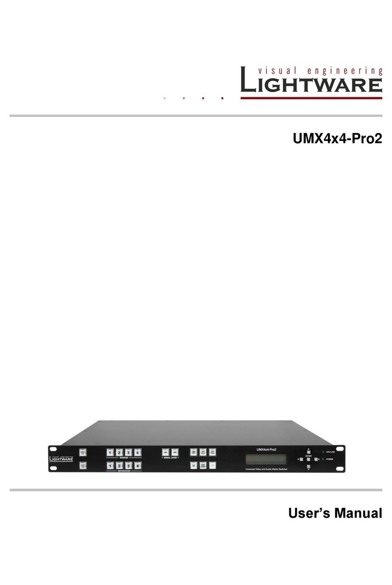
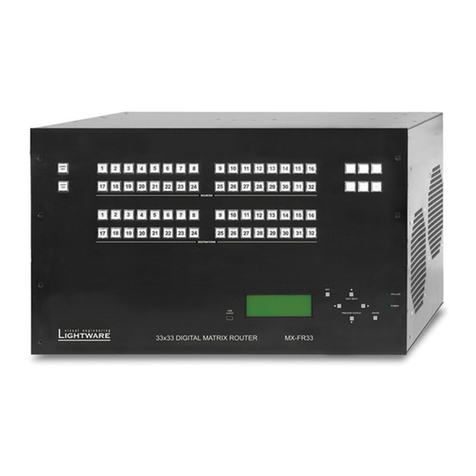
Lightware MX8x8HDMI-Pro User manual

MX8x8HDMI-PRO
MX8x8DVI-HDCP-PRO
User’s manual


IMPORTANT SAFETY INSTRUCTIONS
Class I apparatus construction.
This equipment must be used with a mains power system with a protective earth connection.
The third (earth) pin is a safety feature, do not bypass or disable it. The equipment should
be operated only from the power source indicated on the product.
To disconnect the equipment safely from power, remove the power cord from the rear of the
equipment, or from the power source. The MAINS plug is used as the disconnect device,
the disconnect device shall remain readily operable.
There are no user-serviceable parts inside of the unit. Removal of the cover will expose
dangerous voltages. To avoid personal injury, do not remove the cover. Do not operate
the unit without the cover installed. The appliance must be safely connected to multimedia
systems. Follow instructions described in this manual.
Replacing the AC fuse
Unplug the AC power cord from the device. Locate the AC fuse on the rear panel. Replace
only the AC fuse as indicated on the rear panel. Connect the power cord to the switcher and
to the AC power source. Make sure the switcher is working properly.
Ventilation
For the correct ventilation and to avoid overheating ensure enough free space around the
appliance. Do not cover the appliance, let the ventilation holes free and never block or
bypass the ventilators (if any).
WARNING
To prevent injury, the apparatus is recommended to securely attach to the oor/wall or
mount in accordance with the installation instructions. The apparatus shall not be exposed
to dripping or splashing and that no objects lled with liquids, such as vases, shall be
placed on the apparatus. No naked ame sources, such as lighted candles, should be
placed on the apparatus.
Common Safety Symbols
WEEE ( Waste Electrical & Electronic Equipment )
This marking shown on the product or its literature, indicates that it should
not be disposed with other household wastes at the end of its working life. To
prevent possible harm to the environment or human health from uncontrolled
waste disposal, please separate this from other types of wastes and recycle it
responsibly to promote the sustainable reuse of material resources.
Household users should contact either the retailer where they purchased this
product, or their local government ofce, for details of where and how they can take this
item for environmentally safe recycling. Business users should contact their supplier and
check the terms and conditions of the purchase contract. This product should not be mixed
with other commercial wastes for disposal.
CAUTION AVIS
RISK OF ELECTRIC SHOCK
DO NOT OPEN
RISQUE DE CHOC ELECTRIQUE
NE PAS OUVRIR
Alternating current Caution, possibility of
eletric shock
Protective conductor terminal Caution
MX8x8HDMI-Pro series
User’s manual
Safety instructions Page 3 / 81

Limited Warranty Statement
1. Lightware Visual Engineering LLC (Lightware) warrants to all trade and end user
customers that any Lightware product purchased will be free from manufacturing defects in
both material and workmanship for three (3) years from purchase unless stated otherwise
below. The warranty period will begin on the latest possible date where proof of purchase/
delivery can be provided by the customer. In the event that no proof can be provided
(empty ‘Date of purchase’ eld or a copy of invoice), the warranty period will begin from the
point of delivery from Lightware.
1.1. 25G and MODEX product series will be subject to a seven (7) year warranty period
under the same terms as outlined in this document.
1.2. If during the rst three (3) months of purchase, the customer is unhappy with any
aspect of a Lightware product, Lightware will accept a return for full credit.
1.3. Any product that fails in the rst six (6) months of the warranty period will automatically
be eligible for replacement and advanced replacement where available. Any replacements
provided will be warranted for the remainder of the original unit’s warranty period.
1.4. Product failures from six (6) months to the end of the warranty period will either be
repaired or replaced at the discretion of Lightware. If Lightware chooses to replace the
product then the replacement will be warranted for the remainder of the original unit’s
warranty period.
2. The above-stated warranty and procedures will not apply to any product that has been:
2.1. Modied, repaired or altered by anyone other than a certied Lightware engineer
unless expressly agreed beforehand.
2.2. Used in any application other than that for which it was intended.
2.3. Subjected to any mechanical or electrical abuse or accidental damage.
2.4. Any costs incurred for repair/replacement of goods that fall into the above categories
(2.1., 2.2., 2.3.) will be borne by the customer at a pre-agreed gure.
3. All products to be returned to Lightware require a return material authorization number
(RMA) prior to shipment and this number must be clearly marked on the box. If an RMA
number is not obtained or is not clearly marked on the box, Lightware will refuse the
shipment.
3.1. The customer will be responsible for in-bound and Lightware will be responsible for
out-bound shipping costs.
3.2. Newly repaired or replaced products will be warranted to the end of the originally
purchased products warranty period.
In case of defect please call your local representative or contact Lightware at
Lightware Visual Engineering
Peterdy 15, Budapest H-1071, Hungary
E-mail: [email protected]
Page 4 / 81 Limited Warranty Statement

6.3.2. Tile view............................................. 34
6.3.3. Port properties and settings............... 37
6.3.4. Presets .............................................. 39
6.4. EDID mEnu................................................. 40
6.4.1. EDID operations ................................ 40
6.4.2. EDID summary window ..................... 41
6.4.3. Editing an EDID ................................. 42
6.4.4. Easy EDID Creator ............................ 42
6.5. SEttIngS mEnu ............................................ 43
6.5.1. Conguration ..................................... 43
6.5.2. Device information............................. 44
6.5.3. Status ................................................ 44
6.5.4. Log..................................................... 44
6.5.5. User preferences ............................... 45
6.6. tErmInal wInDow ........................................ 46
7. PROGRAMMERS' REFERENCE ............... 47
7.1. Protocol DEScrIPtIon................................. 47
7.2. gEnEral commanDS ..................................... 47
7.2.1. View product type .............................. 47
7.2.2. View rmware version of the CPU..... 47
7.2.3. View serial number ............................ 48
7.2.4. Compile time...................................... 48
7.2.5. View installed boards......................... 48
7.2.6. View rmware for all controllers......... 48
7.2.7. Restart the device.............................. 49
7.2.8. Query health status .......................... 49
7.2.9. View current communication protocol 49
7.2.10. Set communication protocol ............ 49
7.2.11. Count HDCP keys............................ 49
7.2.12. Clear HDCP key cache.................... 50
7.3. Port SEttIngS ............................................ 50
7.3.1. Switch one input to one output .......... 50
7.3.2. Switch one input to all outputs........... 50
7.3.3. Mute specied output ........................ 51
7.3.4. Unmute specied output.................... 51
7.3.5. Lock the output .................................. 51
7.3.6. Unlock the output............................... 51
7.3.7. View connection state........................ 52
7.3.8. View mutes on all outputs.................. 52
7.3.9. Save preset ....................................... 52
7.3.10. Load preset...................................... 53
7.3.11. View preset without loading ............. 53
7.3.12. Name Presets.................................. 53
7.3.13. Name inputs .................................... 53
7.3.14. Name outputs .................................. 54
7.3.15. Query preset name.......................... 54
7.3.16. Query input name ............................ 54
7.3.17. Query output name.......................... 54
7.3.18. Reload default preset names........... 54
7.3.19. Reload default input names............. 55
7.3.20. Reload default output names........... 55
7.4. nEtwork confIguratIon .............................. 55
7.4.1. Query the current IP conguration..... 55
7.4.2. Reload factory default IP settings...... 56
7.4.3. Enable DHCP IP setting .................... 56
TABLE OF CONTENTS
1. INTRODUCTION ........................................... 8
1.1. Box contEntS ............................................... 8
1.2. DEScrIPtIon.................................................. 8
1.3. fEaturES ...................................................... 8
2. INSTALLATION AND CONTROLS ............. 10
2.1. mountIng ................................................... 10
2.2. connEctIng StEPS....................................... 10
2.3. front vIEw ................................................. 11
2.4. rEar vIEw................................................... 12
2.4.1. MX8x8HDMI-PRO ............................. 12
2.4.2. MX8x8DVI-HDCP-PRO ..................... 13
2.5. ElEctrIcal connEctIonS .............................. 13
2.5.1. HDMI connector................................. 13
2.5.2. DVI-I connector.................................. 13
2.5.3. S/PDIF connector .............................. 14
2.5.4. Ethernet connector (LAN port)........... 14
2.5.5. RS-232 / RS-422 connector .............. 14
3. TECHNOLOGIES........................................ 15
3.1. BaSIcS........................................................ 15
3.2. common ProBlEmS rElatED to EDID............ 15
3.3. aDvancED EDID managEmEnt ...................... 15
3.4. HDcP managEmEnt.................................... 16
3.4.1. Protected and unprotected content ... 16
3.4.2. Real life examples ............................. 17
3.5. PIxEl accuratE rEclockIng ........................ 18
4. OPERATION................................................ 19
4.1. PowErIng on .............................................. 19
4.2. front PanEl oPEratIon................................ 19
4.2.1. Take / Autotake mode ........................ 19
4.2.2. View crosspoint state......................... 20
4.2.3. View live inputs and attached sinks... 20
4.2.4. Save or load presets.......................... 20
4.2.5. Output lock ........................................ 22
4.2.6. Control lock........................................ 22
4.2.7. IP settings.......................................... 23
4.2.8. Control protocols .............................. 24
4.3. front PanEl lcD mEnu oPEratIon ............... 25
4.3.1. Menu concept .................................... 25
4.3.2. Normal mode ..................................... 26
4.3.3. EDID mode ........................................ 27
4.3.4. Signal Present mode ......................... 28
4.4. SoftwarE control moDES ........................... 28
5. SOFTWARE CONTROL – USING
LIGHTWARE BUILT-IN WEB...................... 29
5.1. EStaBlISHIng tHE connEctIon ....................... 29
5.2. tHE layout of tHE BuIlt-In wEB .................... 29
6. SOFTWARE CONTROL - USING
LIGHTWARE DEVICE CONTROLLER ...... 30
6.1. InStall anD uPgraDE.................................... 30
6.2. EStaBlISHIng tHE connEctIon ....................... 31
6.3. croSSPoInt mEnu ........................................ 32
6.3.1. Grid view............................................ 32
MX8x8HDMI-Pro series
User’s manual
Table of contents Page 5 / 81

TABLE OF CONTENTS
7.5. EDID routEr commanDS.............................. 56
7.5.1. Change EDID on input....................... 56
7.5.2. Change EDID on all inputs ................ 56
7.5.3. Save EDID to user memory............... 57
7.5.4. View emulated EDIDs on all inputs ... 57
7.5.5. Watch EDID validity table .................. 57
7.5.6. View EDID header ............................. 58
7.5.7. Delete EDID from memory ................ 58
7.5.8. Download EDID content .................... 58
7.5.9. Upload EDID content to the router .... 59
7.6. Port StatuS commanDS................................ 59
7.6.1. Input port status................................. 59
7.6.2. Output port status .............................. 60
7.6.3. Get information about input port ........ 60
7.6.4. Get information about output port...... 65
7.6.5. Set HDMI output port parameters...... 67
7.6.6. Color range conversion settings ........ 68
7.6.7. Measure timing parameters............... 68
7.7. ProgrammErS' rEfErEncE – QuIck Summary . 70
8. FIRMWARE UPGRADE .............................. 72
8.1. uPgraDIng StEPS In anutSHEll .................... 72
8.2. DEtaIlED InStructIonS ................................. 72
9. TROUBLESHOOTING ................................ 76
10. APPENDIX ................................................ 77
10.1. SPEcIfIcatIon ............................................ 77
10.2. factory DEfaultS SEttIngS........................ 78
10.3. mEcHanIcal DrawIngS................................ 79
10.4. factory EDID lISt ................................... 80
11. DOCUMENT REVISION HISTORY ........... 81
Page 6 / 81 Table of contents

SYMBOL LEGEND
INFO
A notice which may contain useful information. Procedure can be successful without
reading it.
ATTENTION!
An attention which is recommended to read! Procedure can be unsuccessful without
reading it.
WARNING!
Important warning which is highly recommended to read and keep in every case!
TIPS AND TRICKS
Tips and tricks which you may have not known yet but can be useful.
Printer icon
Lightware Visual Engineering supports green technologies and eco-friend mentality.
Thus, this document is made for digital usage primarily. If you need to print out few pages
for any reason, we indicated some summary sheets with a printer-friendly icon which can
be found at the left bottom corner of the actual page.
DOCUMENT INFORMATION
This User’s Manual applies to the following versions of the mentioned software, rmware, and
hardware:
Item Version
Lightware Device Controller (LDC) software 1.10.1b0
Lightware Bootloader software 3.3.3
MX-DVI-CPU rmware 2.5.0
Control Panel (CP1) rmware 1.0.8
MX-DVI-EDID card rmware 2.3.5
Built-in Web Server 1.1.6
Built-in Web Content 1.4.1
Motherboard hardware revision 1.1
Slot 1 hardware revision 1.1
Slot 2 hardware revision 1.2
Control Panel (CP1) hardware revision 2.1
Document revision: 2.0
Release date: 26-10-2016
Editor: Tamas Forgacs
MX8x8HDMI-Pro series
User’s manual
Document information Page 7 / 81

1. Introduction
Thank You for choosing MX8x8HDMI-Pro series matrix. The product is a professional 8 in 8
out HDMI router with HDCP 1.2, HDMI 1.3, and DVI 1.0 compatibility, has 60 meters cable
compensation on all inputs, and contains S/PDIF digital audio breakout for every output.
1.1. Box contents
1.2. Description
MX8x8HDMI-Pro digital video router is the most advanced HDMI router that supports DVI
1.0 HDCP 1.3 and even HDMI 1.3 deep colour standards. This highest performance routing
switcher offers 8 inputs and 8 outputs with HDMI connectors. The built-in sophisticated
software and hardware features make the router the most exible and integrated solution
for AV professionals and high end home theatre applications. Any input can be switched to
any or more outputs without switching delay or frame latency. Supporting the latest HDMI
1.3 36 bit deep colour standard, it can be connected even to the latest BluRay players, set
top boxes, AV receivers. Advanced HD audio transmission and sample rate conversion
proves the compatibility with previous generation products whilst handling the nest Dolby
TrueHD and DTS-HD formats as well. DVI, HDMI and HDCP signals can be seamlessly
integrated in any AV system using Lightware MX8x8HDMI-Pro.
All inputs are equalized and reclocked for up to 60 meter long DVI copper cable, and all
outputs of the matrix router are reclocked for stable, jitter free signal transmission. The unit
can be controlled either by RS-232 / RS-422 port or TCP/IP LAN connection or by built-in
website.
1.3. Features
Zero frame delay
No latency during input/output port switching.
Advanced EDID management
User can emulate any EDID on the input ports, read out and store any monitor's EDID in
the internal memory.
HDCP-compliant
The matrix fullls the HDCP standard. HDCP capability on the digital video inputs can be
disabled when non-protected content is extended.
Pixel Accurate Reclocking
Removes jitter caused by long cables; the output has a clean, jitter free signal, eliminating
signal instability and distortion caused by long cables or connector reections.
MX8x8HDMI-Pro series
matrix
IEC power cable 9-pole D-sub male to
female cable
Safety and
warranty
info
Quick
Start
Guide
UTP cross-link cable Safety and warranty info,
Quick Start Guide
Page 8 / 81 Chapter 1. Introduction

Non-blocking cross point matrix architecture
The router allows any input to be switched to any output or more outputs simultaneously.
2.25 Gb/s channel transmission
Routes any DVI single link signal between 25 and 225 MHz pixel clock frequency conforming
to DVI 1.0 and HDMI1.3 standards.
Frame detector and signal analysis
Using Lightware Device Controller software the exact video and audio signal format can be
determined such as timing, frequencies, scan mode, HDCP encryption, color range, color
space and audio sample rate.
Dolby TrueHD and DTS-HD audio
The matrix has Dolby TrueHD and DTS-HD audio support.
Supports all HDTV resolutions
720p, 1080i, 1080p 2K etc. HDTV signals up to 225 MHz pixel clock frequency regardless
of the actual resolution passed through the router.
Relegendable buttons
Each button has an easy removable at cap and a translucent label that can be inserted
under the cap to identify sources and destinations.
60 meter input cable compensation
Using 22AWG high quality DVI or HDMI cable, the inputs are automatically compensated
for up to 60-meter cable length at 24bpp, which extends installation possibilities even at the
highest HDTV or computer resolutions.
LCD menu control
Control the device locally with using the navigation buttons and the 2 line high LCD menu.
RS-232 / RS-422 controlling
Unit can be controlled over serial data communication with standard RS-232 or RS-422.
Ethernet control
Multiple simultaneous TCP/IP connections are available with a simple ASCII-based protocol
for controlling, conguring the matrix or perform a rmware upgrade.
Color space and color range conversion
Video signals can be converted between RGB, YUV 4:4:4 and YUV 4:2:2 signals in all
directions. Converting between limited and full range is also possible.
Deep Color support and conversion
It is possible to transmit the highest quality 30-bit or 36-bit video streams for perfect color
reproduction. The signal can be converted freely on each output so you can get the best
possible quality on every display.
DVI/HDMI conversion
The router is able to convert between DVI and HDMI signals so that you can watch HDMI
videos on your computer display without audio.
MX8x8HDMI-Pro series
User’s manual
Chapter 1. Introduction Page 9 / 81

2. Installation and controls
2.1. Mounting
The housing of MX8x8HDMI-Pro series matrix contains
built-in rack ears with mounting holes for the easy setup in
rackmount enclosures and any rack environment.
The matrix is 1U high rack sized.
ATTENTION!
To ensure the correct ventilation and avoid overheating let enough free space around the
appliance. Do not cover the appliance, let the ventilation holes free on both sides.
2.2. Connecting steps
1Connect the HDMI/DVI cable(s) between the source(s) to the input port(s) of the
matrix.
2Connect the HDMI/DVI cable(s) between the sink(s) and the output port(s) of the
matrix.
3Optionally for S/PDIF audio extension: connect the audio cable(s) between the
audio device (e.g. power amplier) and the S/PDIF output port(s) or the matrix. *
4Optionally for serial extension: connect a controller device (e.g. touch panel) to
the RS-232 / RS-422 port.
5Optionally connect the matrix to a LAN in order to control the device.
6Firstly connect the power cable to the AC input connector on the matrix, then to
the AC power socket.
* Only MX8x8HDMI-PRO model contains S/PDIF audio output ports.
Touch panel
Ethernet
HDMI/DVI
(8x)
LAN
6
2
Audio
cable
(8x) *
RS-232 /
RS-422
4
Power
amplifier
Power
HDTV
HDMI/DVI
(8x)
1
PC
3
5
Page 10 / 81 Chapter 2. Installation and controls

2.3. Front view
MX8x8HDMI-PRO and MX8x8DVI-HDCP-PRO
1Control Lock
button
Pushing this button results locking of the front panel operation.
Button lights in red when function is enabled. For more details
about this function see section 4.2.6 on page 22.
2Sources buttons Input selector buttons have two functions: to select an output,
or to view the selected output’s state.
3Take / Autotake
button
Button has two functions: displays the actual switching mode
of the router (TAKE mode or AUTOTAKE mode) or executes
switching in TAKE mode. For more details about these modes
see section 4.2.1 on page 19.
4Load Preset
button
Loads and executes a previously saved preset from one of the
preset memories. For more details see section 4.2.4 on page
20.
5Save Preset
button
Stores actual matrix state in one of preset memories. For more
details see section 4.2.4 on page 20.
6LCD display 2x16-character LCD display for menu operations. For more
details about see section 4.3 on page 25.
7Navigation
buttons
UP, DOWN, LEFT, RIGHT, ENTER buttons for menu navigation.
8Status LEDs LEDs give feedback about the actual status of the matrix.
CPU LIVE dark: the device is not operational.
blinks: the device is in normal operation.
POWER dark: device is not powered.
lights: device is powered on.
9Output Lock
button
Locks and protects one (or more) outputs. It inhibits accidental
input changing on protected outputs.
qDestinations
buttons
Output selector buttons have two functions: to select an output,
or to view the selected output’s state.
wEDID button Switches the LCD to EDID menu allowing EDID switch, EDID
save, etc. For more details about this function see section
4.3.3 on page 27.
eSignal Present
button
Displays live sources and attached sinks on source and
destination buttons.
rReset button Hardware reset button. It resets the whole router, however
saved settings, presets and EDIDs will be preserved.
1 72
9 q
6
43 5 8
w e r
MX8x8HDMI-Pro series
User’s manual
Chapter 2. Installation and controls Page 11 / 81

2.4. Rear view
2.4.1. MX8x8HDMI-PRO
1AC power connector Standard IEC power connector. The router works with
100 to 240 Volts, 50 or 60 Hz power sources.
2RS-232 / RS-422
connector
D-sub connector for the serial communication
controlling the device.
3Input ports and status
LEDs
8x HDMI 1.3 connectors for the sources and status
LEDs for each inputs.
4Input Card Active LED LED gives feedback about actual status of the input
card.
5LAN port Standard RJ45 connector for Ethernet connection
controlling the device and performing rmware
upgrade.
6Output ports 8x HDMI 1.3 connectors and 8x S/PDIF audio output
ports for each HDMI outputs.
7Output Card Active LED LED gives feedback about actual status of the output
card.
Input port status LEDs
HDCP LED
dark: input signal is not HDCP-encrypted.
lights: input signal is HDCP-encrypted.
HDMI LED
dark: input signal is DVI.
lights: input signal is HDMI.
SCDT LED (Signal Detected)
dark: video signal is not detected.
lights: valid video signal is detected and sync can be extracted.
+5V LED
dark: source is not connected or not powered.
lights: Source is connected and powered.
Input and output card activity LEDs
dark: card is not active.
lights: card is active and operational.
1234
5 6 7
Page 12 / 81 Chapter 2. Installation and controls

2.4.2. MX8x8DVI-HDCP-PRO
1AC power connector Standard IEC power connector. The router works with
100 to 240 Volts, 50 or 60 Hz power sources.
2RS-232 / RS-422
connector
D-sub connector for the serial communication
controlling the device.
3Input ports 8x DVI-I 1.0 connectors for the connection of the
sources.
4Input Card Active LED LED gives feedback about actual status of the input
card.
5LAN port Standard RJ45 connector for Ethernet connection
controlling the device and performing rmware
upgrade.
6Output ports 8x DVI-I 1.0 connectors for the connection of the
destinations.
7Output Card Active LED LED gives feedback about actual status of the output
card.
Input and output card activity LEDs
dark: card is not active.
lights: card is active and operational.
2.5. Electrical connections
2.5.1. HDMI connector
MX8x8HDMI-PRO matrix provides 8x input and 8x output standard 19
pole HDMI connectors. Always use high quality HDMI cable for connecting
sources and displays.
2.5.2. DVI-I connector
MX8x8DVI-HDCP-PRO contains 8x input and 8x output 29
pole DVI-I connectors. Users can plug in any DVI connector,
but keep in mind that analog signals (such as VGAor RGBHV)
are processed only on certain sinks. Always use high quality DVI cable for connecting
sources and displays.
Fiber Cable powering
As a special feature, Pro series matrix switchers provide 500 mA current on +5V output (pin
14 on DVI output connectors and pin 18 on HDMI output connectors) which is sufcient to
supply power to ber optical DVI cables. Standard DVI outputs or VGA cards only supply
55 mA current on +5V output, thus they are unable to directly power a ber optical cable.
1234
5 6 7
MX8x8HDMI-Pro series
User’s manual
Chapter 2. Installation and controls Page 13 / 81

2.5.3. S/PDIF connector
MX8x8HDMI-PRO matrix provides standard RCA receptacles for digital coaxial
audio outputs.
ATTENTION!
Plugs and sockets on consumer equipment are conventionally color-coded by CEA/CEDIA-
863-B (ANSI) to aid correct connections. According to the standard Lightware uses orange
colored RCA connectors for S/PDIF signals.
2.5.4. Ethernet connector (LAN port)
The matrix switcher provides standard RJ45 connectors for LAN port. Always
use high quality Ethernet cable.
Wiring LAN cables
Lightware recommends the termination of LAN cables on the basis of TIA/EIA T 568 A or
TIA/EIA T 568 B standards.
Pin TIA/EIA T568 A Color and name TIA/EIA T568 B Color and name
1white/green stripe white/orange stripe
2green solid orange solid
3white/orange stripe white/green stripe
4blue solid blue solid
5white/blue stripe white/blue stripe
6orange solid green solid
7white/brown stripe white/brown stripe
8brown solid brown solid
2.5.5. RS-232 / RS-422 connector
The matrix contains RS-232 / RS-422 port which can be connected by an
industry standard 9 pole D-sub female connector.
ATTENTION!
The serial connection standard of the port is pre-dened and not changeable by the user.
User must choose one of the standards (RS-232 or RS-422) before ordering the matrix.
1
8
Top
8
1
Bottom Side
Page 14 / 81 Chapter 2. Installation and controls

3. Technologies
3.1. Basics
EDID stands for Extended Display Identication Data. Simply put, EDID is the passport of
display devices (monitors, TV sets, projectors). It contains information about the display’s
capabilities, such as supported resolutions, refresh rates (these are called Detailed
Timings), the type and manufacturer of the display device, etc.
After connecting a DVI source to a DVI display, the source reads out the EDID to determine
the resolution and refresh rate of the image to be transmitted.
EDID communication
Most DVI computer displays have 128-byte long EDID structure. However, Digital Televisions
and HDMI capable displays may have another 128 bytes, which is called E-EDID (Extended
EDID) and dened by CEA (Consumer Electronics Association). This extension contains
information about additional Detailed Timings, audio capabilities, speaker allocation and
HDMI capabilities. It is important to know, that all HDMI capable devices must have CEA
extension, but not all devices are HDMI capable which have the extension.
3.2. Common problems related to EDID
Problem: „I have changed to a different EDID on MX8x8HDMI-PRO to have a
different resolution but nothing happens.”.
Solution: Some graphics cards and video sources read out the EDID only after
power-up and later they don’t sense that EDID has been changed.
You need to restart your source to make it read out the EDID again.
Problem: „I have a MX8x8DVI-HDCP-PRO and I’m using a Lightware factory
preset EDID. I would like to be able to choose from different
resolutions, but my source allows only one resolution.”
Solution: Most Lightware factory preset EDIDs allow only one resolution, forcing
the sources to output only that particular signal. You need to select
the Universal EDID that supports all common VESA resolutions, see
the factory EDID list.
3.3. Advanced EDID Management
Each DVI sink (e.g. monitors, projectors, plasma displays, and switcher inputs) must
support the EDID data structure. Source BIOS and operating systems are likely to query
the sink using DDC2B protocol to determine what pixel formats and interface are supported.
DVI standard makes use of EDID data structure for the identication of the monitor type
and capabilities. Most DVI sources (VGA cards, set-top boxes, etc.) will output DVI signal
after accepting the connected sink’s EDID information. In case of EDID readout failure or
missing EDID, the source will not output DVI video signal.
Who are
you? I am a monitor.
Here is my EDID.
Now I know what
I can send.
MX8x8HDMI-Pro series
User’s manual
Chapter 3. Technologies Page 15 / 81

The transmitters provide Lightware’s Advanced EDID Management function that helps
system integration. The transmitter’s built-in memory stores and emulates pre-programmed
factory EDIDs, user’s EDID and the monitor's EDID that is connected to the receiver. The
transmitter stores the EDID of the attached monitor or projector in a non-volatile memory.
This way the EDID from a monitor is available when the monitor is unplugged or switched
off.
The EDID emulated on the HDMI / DVI / DP input can be copied from the transmitter's
memory (static EDID emulation), or from the last attached monitor’s memory (dynamic
EDID emulation). For example, the transmitter can be set up to emulate a device, which is
connected to the receiver’s DVI output. In this case, the EDID is automatically changed, if
the monitor is replaced with another display device (as long as it has a valid EDID).
Advanced EDID management can be controlled via Lightware Device Controller.
INFO
EDID settings are available in the transmitter only, the receiver is transparent in the video
signal point of view.
INFO
The user is not required to disconnect the HDMI / DVI / DP cable to change an EDID as
opposed to other manufacturer’s products. EDID can be changed even if the source is
connected to the input and powered ON.
INFO
When EDID has been changed, the transmitter toggles the HOTPLUG signal for 2 seconds.
Some sources do not observe this signal, so in this case the change is not recognized by
the source. In such cases, the source device must be restarted or powered OFF and ON
again.
3.4. HDCP Management
Lightware Visual Engineering is a legal HDCP adopter. Several functions have been
developed which help to solve HDCP related problems. Complex AV systems often have
both HDCP and non-HDCP components. The extenders allow transmitting HDCP encrypted
and unencrypted signals. The devices will be still HDCP compliant as they will never output
an encrypted signal to a non-HDCP compliant display device. If an encrypted signal is
switched to a non-compliant output, a red screen alert or muted screen will be shown.
3.4.1. Protected and unprotected content
Many video sources send HDCP protected signal if they detect that the sink is HDCP
capable – even if the content is not copyrighted. This can cause trouble if an HDCP capable
device (e.g. an extender-pair) is connected between the source and the display. In this
case, the content cannot be viewed on non-HDCP capable displays and interfaces like
event controllers.
Rental and staging technicians often complain about certain laptops, which always send
HDCP encrypted signals if the receiver device (display, matrix router, etc.) reports HDCP
compliancy. However, HDCP encryption is not required all the time e.g. computer desktop
image, certain laptops still do that.
To avoid unnecessary HDCP encryption, Lightware introduced the HDCP enabling/disabling
function: the HDCP capability can be disabled on the extenders. If HDCP is disabled, the
connected source will detect that the sink is not HDCP capable, and turn off authentication.
Page 16 / 81 Chapter 3. Technologies

3.4.2. Real life examples
HDCP-compliant sink
HDCP-compliant sink
All the devices are HDCP-compliant, no manual setting is required, both protected and
unprotected content is transmitted and displayed on the sink.
Non-HDCP compliant sink 1.
Non-HDCP compliant sink displaying unprotected content
Non-HDCP compliant sink is connected to the receiver. Some sources (e.g. computers)
always send HDCP encrypted signals if the receiver device reports HDCP compliancy,
however, HDCP encryption is not required all the time (e.g. computer desktop image). If
HDCP is enabled in the receiver, the image will not be displayed on the sink.
Setting the HDCP parameter to Auto on the output port and disable HDCP on the input port,
the transmitted signal will not be encrypted if the content is not protected. Thus, non-HDCP
compliant sinks will display non-encrypted signal.
Non-HDCP compliant sink 2.
Non-HDCP compliant sink and protected content
The layout is the same as in the previous case: non-HDCP compliant display device is
connected to the receiver but the source would send protected content with encryption. If
HDCP is enabled on the output port of the receiver, the source will send encrypted signal.
The sink is not HDCP-compliant, thus, it will not display the video signal (but blank/red/
muted/etc. screen). If HDCP is disabled on the output port of the receiver, the source will
not send the signal. The solution is to replace the display device to an HDCP-capable one.
Protected
content
HDCP-compliant
sink
Encrypted
signal
Encrypted
signal
MX8x8HDMI-PRO series matrix
HDMI/DVI cable
HDMI/DVI cable
Unprotected
content
Non-HDCP
compliant sink
Non-encrypted
signal
Non-encrypted
signal
MX8x8HDMI-PRO series matrix
HDMI/DVI cableHDMI/DVI cable
Non-HDCP
compliant sink
Encrypted
signal
MX8x8HDMI-PRO series matrix
HDMI/DVI cableHDMI/DVI cable
Protected
content
MX8x8HDMI-Pro series
User’s manual
Chapter 3. Technologies Page 17 / 81

3.5. Pixel Accurate Reclocking
Signal reclocking is an essential important procedure in digital signal transmission. After
passing the reclocking circuit, the signal becomes stable and jitter-free, and can be
transmitted over more equipment like processors, or event controllers. Without reclocking,
sparkles, noise and jaggies can be seen on the image.
Lightware’s sophisticated Pixel Accurate Reclocking technology xes more problems than
general TMDS reclocking. It removes not only intra-pair skew but inter-pair skew as well.
The Pixel Accurate Reclocking circuit eliminates the following errors:
Intra-pair skew: skew between the + and - wires within a differential wire pair (e.g. Data2- and
Data2+). It’s caused by different wire lengths or slightly different wire construction
(impedance mismatch) in DVI cable. It results in jitter.
Inter-pair skew: skew between two differential wire pairs in a cable. It’s caused by different
wire pair lengths or different number of twists in the DVI cable. Too much inter-pair skew
results in color shift in the picture or sync loss.
Jitter: signal instability in the time domain. The time difference between two signal transitions
should be a x value, but noise and other effects cause variations.
Noise: electromagnetic interference between other electronic devices such as mobile
phones, motors, etc. and the DVI cable are coupled onto the signal. Too much noise results
in increased jitter.
Intra-pair skew
+
-
+
-
Inter-pair skew
+
-
Jitter
+
-
Noise
+
-
Page 18 / 81 Chapter 3. Technologies

4. Operation
4.1. Powering on
Connect the power cord to the device’s IEC C14 standard power input connector. The
router is immediately powered ON when the power cord is connected to the AC source (on
Slim-matrices the power switch has to be in position ‘ON’). If the self-test is nished the last
conguration is reloaded and the appliance is ready to use.
INFO
After switching ON, the router reloads the latest settings that were used before it was
turned off. The router has an internal emergency memory that stores all current settings
and tie congurations. This memory is independent from presets and invisible for the user.
This built-in feature helps the system to be ready immediately in case of power failure or
accidental power down.
4.2. Front panel operation
4.2.1. Take / Autotake mode
The router has two different switching modes: TAKE and AUTOTAKE. If the TAKE button
is unlit, TAKE mode is active. When the TAKE button continuously illuminates green,
AUTOTAKE mode is selected. Press and hold the TAKE button for two seconds to change
between TAKE and AUTOTAKE modes.
4.2.1.1. Front panel controls in TAKE mode
Take mode allows the user to connect or disconnect multiple outputs to an input
at once. This mode is useful when the time delay is not allowed between multiple
switching. The commands are only realized when the Take button is pressed.
Switching operation
Step 1. First, press and release the desired source
button. The pressed source button and all
destination buttons which are currently
connected to the source lights up.
Step 2. Press and release the desired destination
buttons which have to be (dis)connected to/
from the selected source. The preselected
destination buttons will blink.
Step 3. Press and release Take button; the selected
input is switched to the selected output(s).
4.2.1.2. Front panel controls in AUTOTAKE mode
Autotake mode is useful when immediate actions must be done or fast switching
is needed between sources on a particular destination. In this mode switching
occurs immediately upon pressing one of the input selector buttons.
Switching operation
Step 1. Press and release the desired destination
button. The pressed destination button and
the actually connected source button light up
green. If no source is connected (the output is
muted) no source button will light up.
Step 2. Press and release the desired source
button. The switch action will be executed
immediately. Switching between sources to
the selected destination can be done directly.
TAKE
AUTO
SOURCES
DESTINATIONS
7 8
8
7
1 2 3 4 5 6
1 2 3 4 5 6
SOURCES
DESTINATIONS
7 8
8
7
1 2 3 4 5 6
2 3 4 5 6
1
LOAD
PRESET
SAVE
PRESET
TAKE
AUTO
TAKE
AUTO
SOURCES
DESTINATIONS
7 8
8
7
1 2 3 4 5 6
1 2 3 4 5 6
SOURCES
DESTINATIONS
7 8
8
7
1 2 3 4 5 6
1 2 3 4 5 6
MX8x8HDMI-Pro series
User’s manual
Chapter 4. Operation Page 19 / 81

4.2.2. View crosspoint state
User can check the current switching status on the front panel using front panel buttons.
View mode is slightly different in TAKE or AUTOTAKE modes because of different switching
philosophy of the two modes.
INFO
View mode does not mean, that the router has to be switched in different modes, viewing
and switching can be done after each other, without pressing any special buttons.
View current state in TAKE mode
If the router is in TAKE mode, user can verify both input and output connections. In TAKE
mode no accidental change can be done unless TAKE button is pressed.
Press and release a source button. Now the selected
source button and all destination buttons that are
currently connected to the selected source will light
up. This informative display will remain active for 5
seconds, then all buttons turn unlit.
Sample drawing shows that Input 1 is currently connected to the Output 2, 3, and 5 ports.
If every source, destination and TAKE button is unlit
(the unit is in TAKE mode, and no input was selected
in the last 5 seconds), press and release a destination
button to see its current state. Now the source button,
which is connected to the selected destination, will
light up. If no source button is illuminated, the selected destination is in muted state. Upon
pressing another destination button, the last state of the destination can be seen.
Sample drawing shows that Output 3 is connected to the Input 1 port.
View current state in AUTOTAKE mode
In AUTOTAKE mode only states of destinations can be viewed.
Press and release the required destination button.
Now the source button, which is connected to the
selected destination, will light up. If no source button
is illuminated, the selected destination is in muted
state. Upon pressing another destination button, the
last state of the destination can be seen.
4.2.3. View live inputs and attached sinks
Step 1. Press and release Signal Present button.
Step 2. Input buttons will light
up indicating that active
TMDS clock signal is
present on respective input
connectors. Output buttons will also light up indicating that a powered monitor is
attached to the output. The output circuit senses TMDS pull-up resistors on monitor
side.
Step 3. Press and release Signal Present button to quit this mode.
Sample drawing shows that the current live inputs are 1 and 3, the current live output is
the 8.
4.2.4. Save or load presets
The unit has 32 user programmable presets. Each preset stores a
conguration regarding all input connections for all outputs. All presets
are stored in a non-volatile memory. The router keeps presets even in
case of power down. Memory numbers are assigned to source buttons.
SOURCES
DESTINATIONS
7 8
8
7
1 2 3 4 5 6
1 2 3 4 5 6
SOURCES
DESTINATIONS
7 8
8
7
1 2 3 4 5 6
1 2 3 4 5 6
SOURCES
DESTINATIONS
7 8
8
7
1 2 3 4 5 6
1 2 3 4 5 6
SIGNAL
PRESENT
SOURCES
DESTINATIONS
7 8
8
7
1 2 3 4 5 6
1 2 3 4 5 6
LOAD
PRESET
SAVE
PRESET
SIGNAL
PRESENT
EDID
TAKE
AUTO
LOAD
PRESET
SAVE
PRESET
Page 20 / 81 Chapter 4. Operation
Other manuals for MX8x8HDMI-Pro
1
This manual suits for next models
1
Table of contents
Other Lightware Network Router manuals
Popular Network Router manuals by other brands

Faderfox
Faderfox 4midiloop user manual

q-Tech
q-Tech QSW-3900 user manual

elsner elektronik
elsner elektronik RF-Router-N Technical specifications and installation instructions

Gembird
Gembird IS-BR user manual

NetComm
NetComm NB6PLUS4WN Setup guide

TRONTEQ Electronic
TRONTEQ Electronic ROQ-08F-U-LV-IP54 installation guide