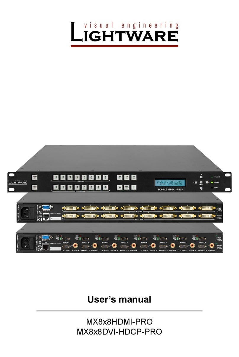
Lightware UMX4x4-Pro2 User manual

UMX4x4-Pro2
User’s Manual


UMX4x4-Pro2
User’s Manual
Page 3 / 136
SAFETY INSTRUCTIONS
Class I apparatus construction.
This equipment must be used with a mains power system with a protective earth connection. The third
(earth) pin is a safety feature, do not bypass or disable it. The equipment should be operated only
from the power source indicated on the product.
To disconnect the equipment safely from power, remove the power cord from the rear of the
equipment, or from the power source. The mains plug is used as the disconnect device, the
disconnect device shall remain readily operable. There are no user-serviceable parts inside of the unit.
Removal of the cover will expose dangerous voltages. To avoid personal injury, do not remove the
cover. Do not operate the unit without the cover installed.
The apparatus shall not be exposed to dripping or splashing and that no objects filled with liquids,
such as vases, shall be placed on the apparatus. No naked flame sources, such as lighted candles,
should be placed on the apparatus.
The appliance must be safely connected to multimedia systems. Follow instructions described in this
manual.
Ventilation
For the correct ventilation and avoid overheating ensure enough free space around the appliance. Do
not cover the appliance, let the ventilation holes free and never block or bypass the ventilators (if any).
WARNING
To prevent injury, the apparatus is recommended to securely attach to the floor/wall or mount in
accordance with the installation instructions.
WEEE ( Waste Electrical & Electronic Equipment )
Correct Disposal of This Product
This marking shown on the product or its literature, indicates that it should not be
disposed with other household wastes at the end of its working life. To prevent
possible harm to the environment or human health from uncontrolled waste disposal,
please separate this from other types of wastes and recycle it responsibly to promote
the sustainable reuse of material resources.
Household users should contact either the retailer where they purchased this product,
or their local government office, for details of where and how they can take this item
for environmentally safe recycling.
Business users should contact their supplier and check the terms and conditions of the purchase
contract. This product should not be mixed with other commercial wastes for disposal.

Page 4 / 136 Section 1. Introduction
Table of contents
1. INTRODUCTION....................................................................................................................................... 9
2. GENERAL DESCRIPTION....................................................................................................................... 9
2.1. BOX CONTENTS.................................................................................................................................... 9
2.2. FEATURES........................................................................................................................................... 9
2.3. TYPICAL APPLICATIONS....................................................................................................................... 11
3. CONTROLS AND CONNECTIONS ....................................................................................................... 12
3.1. FRONT VIEW ...................................................................................................................................... 12
3.2. REAR VIEW ........................................................................................................................................ 13
3.3. PORT DIAGRAMS ................................................................................................................................ 14
3.4. ELECTRICAL CONNECTIONS ................................................................................................................ 15
3.4.1. DVI inputs and outputs ............................................................................................................ 15
3.4.2. Digital audio inputs and outputs............................................................................................... 16
3.4.3. Analog stereo audio inputs and outputs .................................................................................. 16
3.4.1. Ethernet port............................................................................................................................ 17
3.4.1. RS-232 control port.................................................................................................................. 18
4. TECHNOLOGIES ................................................................................................................................... 19
4.1. BASICS.............................................................................................................................................. 19
4.1.1. Common problems related to EDID......................................................................................... 19
4.2. ADVANCED EDID MANAGEMENT ......................................................................................................... 20
4.3. HDCP MANAGEMENT ......................................................................................................................... 21
4.3.1. Mixing encrypted and unencrypted signals ............................................................................. 21
4.3.2. HDPC key caching................................................................................................................... 21
4.3.3. Avoiding unnecessary HDCP encryption................................................................................. 21
4.4. PIXEL ACCURATE RECLOCKING........................................................................................................... 23
4.5. RICOD ............................................................................................................................................. 24
4.5.1. Introduction.............................................................................................................................. 24
4.5.2. RICOD capable devices .......................................................................................................... 24
4.5.3. Operation: Master and Slave mode......................................................................................... 24
4.5.4. Factory defaults ....................................................................................................................... 25
4.5.5. Enable / disable RICOD........................................................................................................... 25
4.5.6. Validity of RICOD..................................................................................................................... 26
4.5.7. Locking the remote device....................................................................................................... 26
4.5.8. An example application............................................................................................................ 27
5. OPERATION........................................................................................................................................... 28
5.1. POWER.............................................................................................................................................. 28
5.2. FRONT PANEL OPERATIONS ................................................................................................................ 28
5.2.1. Signal layers ............................................................................................................................ 28
5.2.2. TAKE / AUTOTAKE modes..................................................................................................... 28
5.2.3. CONTROL LOCK .................................................................................................................... 28
5.2.4. SOURCES and DESTINATIONS buttons ............................................................................... 29
5.2.5. Viewing crosspoint state.......................................................................................................... 29
5.2.6. Switching.................................................................................................................................. 30
5.2.7. Switching operations flowchart................................................................................................ 31
5.2.8. Preset operations..................................................................................................................... 32
5.2.9. OUTPUT LOCK ....................................................................................................................... 32
5.3. ABOUT EDID MEMORY ....................................................................................................................... 34
5.3.1. EDID types............................................................................................................................... 34
5.3.2. Factory EDID list...................................................................................................................... 35
5.4. FRONT PANEL LCD MENU OPERATION................................................................................................. 36
5.4.1. Basic concept........................................................................................................................... 36
5.4.2. Menu structure......................................................................................................................... 36
5.4.3. Navigation................................................................................................................................ 37
5.4.4. Normal mode ........................................................................................................................... 37
5.4.5. EDID mode .............................................................................................................................. 44
5.4.6. Signal Present mode ............................................................................................................... 45

UMX4x4-Pro2
User’s Manual
Section 1. Introduction Page 5 / 136
6. REMOTE OPERATION .......................................................................................................................... 46
6.1.1. Control interfaces..................................................................................................................... 46
6.1.2. User interface comparison....................................................................................................... 46
6.1.3. Multiple simultaneous connections.......................................................................................... 47
6.1.4. Serial port settings................................................................................................................... 47
6.1.5. IP settings................................................................................................................................ 47
6.1.6. Control protocols...................................................................................................................... 47
7. SOFTWARE CONTROL –LIGHTWARE DEVICE CONTROLLER AND WEB..................................... 49
7.1. INSTALLING LIGHTWARE DEVICE CONTROLLER .................................................................................... 49
7.1.1. The normal install .................................................................................................................... 49
7.1.2. The snapshot install................................................................................................................. 49
7.1.3. Steps of the installation in case of Windows OS ..................................................................... 50
7.1.4. Steps of the installation in case of Mac OS X.......................................................................... 52
7.1.5. Upgrading the LDC.................................................................................................................. 53
7.2. ESTABLISHING THE CONNECTION......................................................................................................... 54
7.3. WEB CONTROL –USING BUILT-IN WEBSITE .......................................................................................... 56
7.3.1. Establishing the connection..................................................................................................... 56
7.4. CONTROLLER WINDOW ....................................................................................................................... 57
7.5. CROSSPOINT MENU............................................................................................................................ 58
7.5.1. Grid view.................................................................................................................................. 58
7.5.2. Tile view................................................................................................................................... 60
7.5.3. Input parameter settings.......................................................................................................... 64
7.5.4. Output parameter settings....................................................................................................... 69
7.5.5. Presets..................................................................................................................................... 71
7.5.6. Global port settings.................................................................................................................. 72
7.6. EDID MENU....................................................................................................................................... 73
7.6.1. EDID operations....................................................................................................................... 74
7.7. SETTINGS MENU................................................................................................................................. 76
7.7.1. Configuration............................................................................................................................ 76
7.7.2. Device information................................................................................................................... 77
7.7.3. Status....................................................................................................................................... 77
7.7.4. Log........................................................................................................................................... 78
7.7.5. User preferences (only in LDC)............................................................................................... 79
7.8. TERMINAL WINDOW ............................................................................................................................ 80
8. PROGRAMMERS REFERENCE............................................................................................................ 81
8.1. CHANGING PROTOCOLS...................................................................................................................... 81
8.2. PROTOCOL DESCRIPTION.................................................................................................................... 81
8.3. STORAGE SETTINGS........................................................................................................................... 83
8.4. STATUS AND IDENTIFICATION COMMANDS ............................................................................................ 83
8.4.1. View product type .................................................................................................................... 83
8.4.2. View serial number .................................................................................................................. 83
8.4.3. View Firmware version of the CPU.......................................................................................... 83
8.4.4. View CPU firmware compile time ............................................................................................ 84
8.4.5. View installed controllers’ firmware.......................................................................................... 84
8.4.6. View current control protocol ................................................................................................... 84
8.4.7. Set current control protocol...................................................................................................... 84
8.4.8. View crosspoint size ................................................................................................................ 85
8.4.9. View LAN versions................................................................................................................... 85
8.4.10. View router’s health ................................................................................................................. 85
8.4.11. View installed I/O boards......................................................................................................... 86
8.4.12. View error list........................................................................................................................... 86
8.5. SYSTEM COMMANDS........................................................................................................................... 87
8.5.1. Reload factory defaults............................................................................................................ 87
8.5.2. Count HDCP keys.................................................................................................................... 87
8.5.3. Clear HDCP key cache............................................................................................................ 87
8.5.4. Restart matrix router................................................................................................................ 88
8.6. COMMUNICATION SETUP COMMANDS................................................................................................... 88
8.6.1. Query IP settings ..................................................................................................................... 88

Page 6 / 136 Section 1. Introduction
8.6.2. Reload factory default IP settings............................................................................................ 88
8.6.3. Enable DHCP IP setting .......................................................................................................... 89
8.6.4. Query RS-232 baud rate.......................................................................................................... 89
8.6.5. Change RS-232 baud rate....................................................................................................... 89
8.7. EDID ROUTER COMMANDS ................................................................................................................. 90
8.7.1. Change EDID on input............................................................................................................. 90
8.7.2. Change EDID on all inputs ...................................................................................................... 90
8.7.3. Save EDID to user memory (Learn EDID)............................................................................... 90
8.7.4. View emulated EDIDs on all inputs.......................................................................................... 91
8.7.5. Watch EDID validity table ........................................................................................................ 91
8.7.6. View EDID header ................................................................................................................... 92
8.7.7. Download EDID content from the router.................................................................................. 92
8.7.8. Upload EDID content to the router .......................................................................................... 93
8.7.9. Delete EDID from memory....................................................................................................... 94
8.7.10. View emulated EDIDs type...................................................................................................... 94
8.8. CONTROL COMMANDS ........................................................................................................................ 95
8.8.1. Switch one input to one output ................................................................................................ 95
8.8.2. Switch one input to all outputs................................................................................................. 95
8.8.3. Switch diagonal........................................................................................................................ 96
8.8.4. View connection on output....................................................................................................... 96
8.8.5. View connection on all outputs................................................................................................ 96
8.8.6. Mute specified output............................................................................................................... 97
8.8.7. Unmute specified output.......................................................................................................... 97
8.8.8. Lock specified output............................................................................................................... 97
8.8.9. Unlock specified output............................................................................................................ 97
8.8.10. Save preset to memory location.............................................................................................. 97
8.8.11. Load preset from memory location.......................................................................................... 98
8.8.12. View preset.............................................................................................................................. 98
8.8.13. Rename a preset ..................................................................................................................... 98
8.8.14. Rename an input ..................................................................................................................... 98
8.8.15. Rename an output ................................................................................................................... 98
8.8.16. Read a preset’s name.............................................................................................................. 99
8.8.17. Read an input’s name.............................................................................................................. 99
8.8.18. Read an output’s name............................................................................................................ 99
8.8.19. Reload default preset names................................................................................................... 99
8.8.20. Reload default input names..................................................................................................... 99
8.8.21. Reload default output names................................................................................................... 99
8.9. PORT STATUS COMMANDS ................................................................................................................ 100
8.9.1. Input port status..................................................................................................................... 100
8.9.2. Output port status .................................................................................................................. 100
8.9.3. All port status ......................................................................................................................... 100
8.10. INPUT PROPERTIES........................................................................................................................... 101
8.10.1. Set input port properties ........................................................................................................ 101
8.10.2. Query input port properties.................................................................................................... 104
8.10.3. Reload factory defaults of input port properties..................................................................... 104
8.10.4. Set analog timing properties.................................................................................................. 105
8.10.5. Query analog timing properties.............................................................................................. 105
8.10.6. Reset analog timing properties.............................................................................................. 106
8.10.7. Set analog color properties.................................................................................................... 106
8.10.8. Save analog color properties................................................................................................. 107
8.10.9. Query analog color properties ............................................................................................... 107
8.10.10. Reset analog color properties................................................................................................ 107
8.10.11. Set analog input audio parameters........................................................................................ 107
8.10.12. Query analog input audio properties ..................................................................................... 108
8.10.13. Reset analog input audio properties...................................................................................... 108
8.10.14. Set the color of ‘no sync’ picture............................................................................................ 108
8.10.15. Query the color of ‘no sync’ picture ....................................................................................... 108
8.10.16. Reset the status and the color of ‘no sync’ picture ................................................................ 108
8.10.17. Query timings of the incoming signal..................................................................................... 109
8.11. OUTPUT PROPERTIES....................................................................................................................... 110
8.11.1. Set output video properties.................................................................................................... 110

UMX4x4-Pro2
User’s Manual
Section 1. Introduction Page 7 / 136
8.11.2. Query output video properties ............................................................................................... 111
8.11.3. Reset output video properties................................................................................................ 112
8.11.4. Set output audio properties.................................................................................................... 112
8.11.5. Query output audio properties............................................................................................... 112
8.11.6. Reset analog output audio properties.................................................................................... 112
8.12. RICOD RELATED COMMANDS ........................................................................................................... 113
8.12.1. Set RICOD MASTER status on inputs .................................................................................. 113
8.12.2. Query RICOD MASTER status on inputs.............................................................................. 114
8.12.3. Set RICOD SLAVE status on output ..................................................................................... 114
8.12.4. Query RICOD slave status on output .................................................................................... 114
8.13. ROUTER INITIATED COMMANDS ......................................................................................................... 115
8.13.1. EDID status changed............................................................................................................. 115
8.13.2. Port status changed............................................................................................................... 115
8.14. ERROR RESPONSES ......................................................................................................................... 115
9. COMMANDS –QUICK SUMMARY..................................................................................................... 116
10. FIRMWARE UPGRADE ....................................................................................................................... 119
10.1. INSTALLING THE BOOTLOADER.......................................................................................................... 119
10.1.1. Installing and launching the Bootloader software.................................................................. 119
10.2. UPGRADE PROCESS ......................................................................................................................... 121
10.2.1. Tips for the upgrade process................................................................................................. 121
10.2.2. Firmware upgrade.................................................................................................................. 121
11. TROUBLESHOOTING ......................................................................................................................... 128
11.1. GENERAL PROBLEMS........................................................................................................................ 128
11.2. SERIAL CONNECTION PROBLEMS....................................................................................................... 128
11.3. TCP/IP CONNECTION PROBLEMS ...................................................................................................... 128
11.4. PICTURE IS NOT DISPLAYED OR DISTORTED........................................................................................ 129
11.5. BOOTLOAD ...................................................................................................................................... 129
12. SPECIFICATIONS................................................................................................................................ 131
12.1. MECHANICAL DRAWINGS .................................................................................................................. 133
13. VERSION APPLICABILITY.................................................................................................................. 134
14. WARRANTY ......................................................................................................................................... 135
15. DOCUMENT REVISION HISTORY...................................................................................................... 136


UMX4x4-Pro2
User’s Manual
Section 1. Introduction Page 9 / 136
1. Introduction
Dear Customer,
Thank you for choosing Lightware UMX4x4-Pro2 matrix switcher. It is able to switch 4
inputs to 4 outputs in a non-blocking crosspoint configuration.
The UMX4x4-Pro2, the all-round universal matrix switcher, is the perfect solution for ever-
changing environments such as small board rooms and classrooms. UMX (Universal
MatriX) technology was developed by Lightware to support various analog and digital
audio visual formats. VGA, YUV, digital DVI, HDMI with HDCP, stereo analog and S/PDIF
digital audio signals are all supported.
2. General description
2.1. Box contents
UMX4x4-Pro2 matrix switcher
IEC power cable
LAN UTP crosslink cable, CAT5e type, 3m length
RS-232 straight serial cable (9 pole D-sub Male to Female)
VGA to DVI-D adapter cable (4 pcs.)
User's manual (this document)
2.2. Features
Advanced EDID Management –The user can emulate any EDID on the switcher's
inputs independently, read out and store any attached monitor's EDID
in the internal memory locations, upload and download EDID files
using Lightware Device Controller.
Non-blocking cross point matrix architecture –The router allows any input to be
switched to any output or more outputs simultaneously.
2.25 Gb/s channel transmission –Routes any DVI single link or HDMI signal between
25 and 225 MHz pixel clock frequency conforming to DVI 1.0 and
HDMI1.3 standards.
Supports all HDTV resolutions –720p, 1080i, 1080p 2K etc. HDTV signals up to 225
MHz pixel clock frequency regardless of the actual resolution passed
through the router.
Control by front panel buttons –4 source select, 4 destination select, Video layer,
Audio layer, Take, Load preset, Save preset, EDID function, Signal
present, Control Lock, Output Lock.
Reconfigurable buttons –Each button has a removable flat cap and a translucent label
that can be inserted under the cap to identify sources and
destinations.
RS-232 control –Simple ASCII based RS-232 protocol is used for switching, preset
calling, status request, etc.
Ethernet control –TCP/IP Ethernet 10Base-T or 100Base-TX (Auto- Sensing).
Built-in WEB site –Easy access from a WEB browser to control and configure the
switcher.

Page 10 / 136 Section 2. General description
Universal power supply –UMX4x4-Pro2 matrices accept AC voltages from 100 to 240
Volts with 50 or 60 Hz line frequency on standard IEC connector.
Power failure memory –In case of power failure, the unit stores its latest configuration,
and after next power up it loads automatically.
HDCP compliant –UMX4x4-Pro2 matrices comply with HDCP1.2 standard. Lightware is
a legal HDCP adopter. The included Advanced HDCP Management
eliminates the need for re-authentication upon switching.
20 meter input cable compensation –Using 22AWG high quality DVI or HDMI cable,
the inputs are automatically compensated for up to 20 meter cable
length, which extends installation possibilities even at the highest
HDTV or computer resolutions.
Pixel Accurate Reclocking –(removes jitter caused by long cables) Each output has a
clean, jitter free signal, eliminating signal instability and distortion
caused by long cables or connector reflections.
Frame detector and signal analysis –Using the built-in webpage or Lightware Device
Controller (LDC) software the user can monitor incoming signal
parameters such as resolution, signal timing parameters, audio type,
scan rate, HDCP encryption and so on.
DVI/HDMI conversion –The router is able to convert from HDMI to DVI signals so that
you can watch HDMI videos on your computer display without audio.
Fiber cable support –Self powered DVI fiber cables using +5V from DVI sources (VGA
cards, etc.) usually consume more than 50 mA, which load is
maximum allowed by DVI 1.0 standard. UMX4x4-Pro2 supports +5V
500 mA constant current output on each DVI output to power long
distance fiber optical cables.
Zero frame delay –Even on Analog Inputs - Lightware’s UMX4x4-Pro2 matrix
switchers add no frame delay to the switched signal. There is no
frame or line period delays to the signals when passing a Lightware
router.
Separate Audio and Video matrix switching –Video and audio signals can be
separated and switched independently. Even if the HDMI stream
contains embedded audio.
Analog Audio and Video A/D conversion –UMX4x4-Pro2 matrices convert
uncompressed analog audio and video signal to digital and the digital
or digitized analog audio can be embedded in the video stream.
Accepts analog and digital audio signals –UMX4x4-Pro2 accepts unbalanced analog
stereo; 5.1 S/PDIF and even 7.1 HDMI embedded audio signals.

UMX4x4-Pro2
User’s Manual
Section 2. General description Page 11 / 136
2.3. Typical applications
Some typical connection variations with the matrix router are shown on Figure 2-1.
Figure 2-1. Typical application for UMX4x4-Pro2
Application examples
Small classrooms
Conference rooms, collaborative telepresence
Control room
Multiroom video
Home cinema

Page 12 / 136 Section 3. Controls and connections
3. Controls and connections
3.1. Front view
Figure 3-1. UMX4x4-Pro2 front view
Status LEDs POWER LED indicates that the unit is powered on and CPU
LIVE blinking LED indicates normal operation.
Menu navigation (UP, DOWN, LEFT, RIGHT, ENTER) buttons for menu
navigation.
Menu display 2x16-character LCD display with backlight for menu operations
and settings.
Function buttons Switching between working modes (Normal / EDID / Signal
present, Take / Autotake) and Preset operations are available
with the Function buttons.
Layer select Audio and video signals are placed on different layers so they
can be switched separately or at the same time. Layer select
buttons chose the desired signal(s) to be switched.
Source buttons Source buttons have three functions: select an input, select a
preset number and view the selected input’s state (take mode).
Destination buttons Destination buttons have two functions: select an output, or
view the selected output’s state.
Control lock Disables or enables front panel operation. When it illuminates
red, operations on front panel are prohibited.
Output lock Locks and protects one (or more) outputs. It inhibits accidental
input changing on protected outputs.
Control lock
8
Output lock
9
Status LEDs
1
Layer select
5
Menu display
3
Function buttons
4
Destination buttons
7
Menu navigation
2
Source buttons
6
3
4
5
1
2
6
7
8
9

UMX4x4-Pro2
User’s Manual
Section 3. Controls and connections Page 13 / 136
3.2. Rear view
Figure 3-2. UMX4x4-Pro2 rear view
Inputs UMX4x4-Pro2 has 4 input ports. Each port has one video, one
analog stereo audio and one digital audio input.
DVI-I in Standard 29 pole DVI-I connectors for input connections. It
accepts analog and digital signals.
Analog audio in Double RCA jack connector for unbalanced, analog stereo
audio input signal (left and right channels).
S/PDIF in RCA jack connector for S/PDIF digital audio signal.
Outputs UMX4x4-Pro2 has 4 output ports. Each port has one video, one
unbalanced, analog stereo audio and one digital audio output.
DVI-D out Standard 29 pole DVI connectors for outputs - only digital pins
are connected.
Analog audio out Double RCA jack connector for unbalanced, analog stereo
audio output signal (left and right channels).
S/PDIF out RCA jack connector for S/PDIF digital audio signal. Embedded
audio is still present on the DVI-D outputs.
Reset button Hardware reset button. It resets the whole router, however
saved settings, presets and EDIDs will be preserved.
Ethernet port Standard RJ45 connector. This port can be connected to a
computer directly or to LAN via switch or router.
RS-232 port 9 pole D-sub female connector for standard RS-232 port.
Power Standard IEC power connector. The router works with 100 to
240 Volts, 50 or 60 Hz power sources.
Fuse Replace with F 3.15AL type only.
Inputs
1
Outputs
5
RS-232 Port
11
Ethernet port
10
DVI-I in
2
Power
12
Fuse
13
S/PDIF in
4
Analog audio in
3
Reset button
9
DVI-D out
6
S/PDIF out
8
Analog audio out
7
2
1
3
5
6
7
8
9
10
11
12
13
4

Page 14 / 136 Section 3. Controls and connections
3.3. Port diagrams
Explanation of the device input and output ports:
Figure 3-3. UMX4x4-Pro2 port diagram
Input side:
The DVI-I connector accepts analog (VGA, YUV) or digital (DVI, HDMI) video
signals.
Analog video is always digitalized by the A/D converter of the input port.
The embedded audio is always unwrapped from the HDMI signal by the
de-embedder of the input port.
Analog audio is always digitalized by the A/D converter of the input port.
The input port properties (2/1 video and 3/1 audio switch) determinate which
video (digitalized analog or digital) and which audio (digitalized analog, S/PDIF or
unwrapped) signal reaches the crosspoint.
Output side:
The embedder of the output port wrap the selected audio (selecting by the digital
audio crosspoint) into the HDMI stream.
If the video output is forced to DVI mode, there is no embedded audio.
S/PDIF gives out the selected audio up-to two channels of uncompressed PCM
audio or compressed 5.1/7.1 surround sound (such as DTS audio codec).
(Dolby TrueHD and DTS-HD Master Audio bandwidth needs exceed the standard
S/PDIF capability.)
Analog audio output gives the first two channels of the selected audio, if it is not
compressed (e.g. LPCM).

UMX4x4-Pro2
User’s Manual
Section 3. Controls and connections Page 15 / 136
3.4. Electrical connections
3.4.1. DVI inputs and outputs
DVI Inputs
UMX4x4-Pro2 matrix switchers provide standard 29 pole DVI-I connectors for inputs. This
way, users can plug in any DVI connector, but keep in mind that analog signals (such as
VGA or RGBHV) are processed only on the DVI inputs.
Always use high quality DVI cable for connecting sources and displays.
Pin
Signal
Pin
Signal
Pin
Signal
1
TMDS Data2-
9
TMDS Data1-
17
TMDS Data0-
2
TMDS Data2+
10
TMDS Data1+
18
TMDS Data0+
3
TMDS Data2 Shield
11
TMDS Data1 Shield
19
TMDS Data0 Shield
4
Not Connected inside
12
Not Connected inside
20
Not Connected inside
5
Not Connected inside
13
Not Connected inside
21
Not Connected inside
6
DDC Clock
14
+5V Power
22
TMDS Clock Shield
7
DDC Data
15
GND (for +5V)
23
TMDS Clock+
8
Analog Vertical Sync1
16
Hot Plug Detect
24
TMDS Clock-
C1
Analog Red 1
C2
Analog Green 1
C3
Analog Blue 1
C4
Analog Horizontal Sync 1
C5
GND
Table 3-1. DVI-I connector pin assignments
Figure 3-4. DVI connector
1- These pins are connected only on the DVI inputs.
DVI outputs
29 pole DVI-I connectors for outputs have only digital pins internally connected. This way,
users can plug in any DVI connector, but keep in mind that analog signals (such as VGA
or RGBHV) are NOT available on the outputs.
Fiber Cable powering
DVI outputs are able to supply 500 mA current on DDC +5V output (pin 14 on output
connectors) which is sufficient to supply power to fiber optical DVI cables. Standard DVI
outputs usually supply only 55 mA current on +5V output, thus unable to directly power a
fiber optical cable.
Info: The matrix switcher does not check if the connected sink (monitor, projector or other
equipment) supports Hotplug or EDID signals but outputs the selected signal immediately
after switch command.
C1
C2
C4
C3
1
2
3
4
5
6
7
8
9
10
11
12
13
14
15
16
17
18
19
20
21
22
23
24
C5

Page 16 / 136 Section 3. Controls and connections
3.4.2. Digital audio inputs and outputs
UMX4x4-Pro2 matrix switchers have standard RCA receptacles for digital coaxial audio
inputs and outputs.
RCA receptacle RCA plug
Nr.
Name
1
S/PDIF input or output
2
Plastic insulator
3
GND
Table 3-2. RCA connector pin assignments for digital audio
Info: Plugs and sockets on consumer equipment are conventionally color-coded by
CEA/CEDIA-863-B (ANSI) to aid correct connections. According to the standard
Lightware uses orange colored RCA connectors for S/PDIF signals.
3.4.3. Analog stereo audio inputs and outputs
UMX4x4-Pro2 matrix switchers have standard RCA receptacle for analog stereo audio
inputs and outputs. Inputs and outputs work with standard line-in and line-out voltage
levels.
RCA plug (left channel) RCA receptacles RCA plug (right channel)
Nr.
Name
1
Right channel input or output
2
Plastic insulator
3
GND
4
Left channel input or output
5
Plastic insulator
6
GND
Table 3-3. RCA connector pin assignments for analog audio
Info: Plugs and sockets on consumer equipment are conventionally color-coded by
CEA/CEDIA-863-B (ANSI) to aid correct connections. According to the standard
Lightware uses red colored RCA connectors for right channel of analog stereo audio
signals and white colored RCA connectors for left channel of analog stereo audio signals.
000
0
3
2
1
000
0
000
0
3
2
1
6
5
4

UMX4x4-Pro2
User’s Manual
Section 3. Controls and connections Page 17 / 136
3.4.1. Ethernet port
Lightware UMX4x4-Pro2 matrix switchers can be remote controlled through Ethernet as
well. The Ethernet port can be connected to a LAN hub, switch or router with a UTP patch
cable. If connecting to a computer directly, a cross UTP cable has to be used!
The device contains two bi-color LEDs built into the front of the connector:
LED1
LED2
OFF
no link
no activity
Amber
10 Mbps
half duplex
Green
100 Mbps
full duplex
Blink
N/A
activity
Figure 3-5. RJ45 receptacle connector
See section 6about remote operation on page 46 for more information.
Wiring of RJ45 plugs
Figure 3-6. RJ45 plug
Lightware recommends the termination of TP cables on the basis of TIA/EIA T 568 A or
TIA/EIA T 568 B standards.
Pin
Name
TIA/EIA
T568 A
color and
name
TIA/EIA
T568 B
color
and name
1
TX +
white/green stripe
white/orange stripe
2
TX -
green solid
orange solid
3
RX +
white/orange stripe
white/green stripe
4
Not used
blue solid
blue solid
5
Not used
white/blue stripe
white/blue stripe
6
RX -
orange solid
green solid
7
Not used
white/brown stripe
white/brown stripe
8
Not used
brown solid
brown solid
Table 3-4. Recommended termination of TP cables

Page 18 / 136 Section 3. Controls and connections
3.4.1. RS-232 control port
UMX4x4-Pro2 matrix switchers can be remote controlled through industry standard
9-pole D-SUB female connector. The router can be ordered with RS 232 control port.
Figure 3-7. D-SUB 9 pole female connector (DE9F)
Pin nr.
RS-232
1
NC - not connected
2
TX data transmit (output)
3
RX data receive (input)
4
NC - not connected
5
GND signal ground (shield)
6
NC - not connected
7
NC - not connected
8
NC - not connected
9
NC - not connected
Table 3-5. D-sub connector pin assignment for standard RS-232
1
5
6
9

UMX4x4-Pro2
User’s Manual
Section 4. Technologies Page 19 / 136
4. Technologies
4.1. Basics
EDID stands for Extended Display Identification Data. Simply put, EDID is the passport of
display devices (monitors, TV sets, projectors). It contains information about the display’s
capabilities, such as supported resolutions, refresh rates (these are called Detailed
Timings), the type and manufacturer of the display device, etc.
After connecting a DVI source to a DVI display, the source reads out the EDID to
determine the resolution and refresh rate of the image to be transmitted.
Figure 4-1. EDID communication
Most DVI computer displays have 128-byte long EDID structure. However, Digital
Televisions and HDMI capable displays may have another 128 bytes, which is called E-
EDID and the most common extension is defined by CEA (Consumer Electronics
Association). This extension contains information about additional Detailed Timings,
audio capabilities, speaker allocation and HDMI capabilities. It is important to know, that
all HDMI capable devices must have CEA extension, but not all devices are HDMI
capable which have the extension.
4.1.1. Common problems related to EDID
Problem: „My system consists of the following: a computer, a Lightware UMX4x4-Pro2
matrix, a WUXGA (1920x1200) LCD monitor, and an SXGA (1280x1024)
projector. I would like to see the same image on the monitors and the
projector. What EDID should I chose on the monitor and the projector?”
Solution: If you want to see the image on both displays, you need to select the
resolution of the smallest display (in this case SXGA), otherwise the smaller
display may not show the higher resolution image.

Page 20 / 136 Section 4. Technologies
Problem: „I have changed to a different EDID on an input port of the matrix to have a
different resolution but nothing happens.”
Solution: Some graphics cards and video sources read out the EDID only after power-
up and later they don’t sense that EDID has been changed. You need to
restart your source to make it read out the EDID again.
Problem: „I have a UMX4x4-Pro2 and I’m using a Lightware factory preset EDID. I
would like to be able to choose from different resolutions, but my source
allows only one resolution.”
Solution: Most of the Lightware factory preset EDIDs allow only one resolution, forcing
the sources to output only that particular signal. You need to select a
Universal EDID. It supports all common VESA resolutions. Additionally it
also features audio support.
4.2. Advanced EDID management
Each DVI sink (e.g. monitors, projectors, plasma displays, and switcher inputs) must
support the EDID data structure. Source BIOS and operating systems are likely to query
the sink using DDC2B protocol to determine what pixel formats and interface are
supported. HDMI standard makes use of EDID data structure for the identification of the
monitor type and capabilities. Most DVI sources (VGA cards, set top boxes, etc.) will
output DVI signal after accepting the connected sink’s EDID information. In case of EDID
readout failure or missing EDID the source will not output DVI video signal. UMX4x4-Pro2
provides Lightware’s Advanced EDID Management function that helps system
integration. The built in EDID memory stores and emulates pre-programmed factory
EDIDs, user’s EDIDs and all monitor's EDID that is connected to the output connectors.
The router stores the EDID of all attached monitors or projectors for each output in a
non-volatile memory. This way the EDID from a monitor is available when the monitor is
unplugged, or switched off.
Any EDID can be emulated on any input. An emulated EDID can be copied from the
EDID router's memory (static EDID emulation), or from the last attached monitors
memory (dynamic EDID emulation). For example, the router can be set up to emulate a
device, which is connected to one of the outputs. In this case the EDID automatically
changes, if the monitor is replaced with another display device (as long as it has a valid
EDID).
EDID is independently programmable for all inputs without affecting each other. All inputs
have their own EDID circuit. EDID management can be controlled via serial port or
Ethernet.
Info: The user is not required to disconnect the DVI cable to change an EDID as opposed to
other manufacturer’s products. EDID can be changed even if a source is connected to the
input and it is powered ON.
Info: When EDID has been changed, the router toggles the HOTPLUG signal for 2 seconds.
Some sources do not observe this signal, so in this case the change is not recognized by
the source. In such cases the source device must be restarted or powered OFF and ON
again.
Other manuals for UMX4x4-Pro2
1
Table of contents
Other Lightware Network Router manuals