Lightway LW6P72-340 User manual

Installation Manual
Revision Date Apr. 9, 2020/Applicable for IEC certified products
BaoDing Lightway Green Energy Technology Co., Ltd.
Add : New Industry Park, Gaobeidian,Hebei Province, P.R. China
Tel: +86(312)2951122
Fax: +86(312)2951166
P.C.:074000
Email:in[email protected]
www.lightwaysolar.com
The Energy Depot Australia
Add: 1/4 Bridge Rd Keysborough VIC 3173 Australia.
ABN:75 606 661 321
contact name:John Kurta
Tel: +61 0135842
Fax: N/A
Email: [email protected]
www.theenergydepot.com.au

Lightway PV Modules, Installation Manual, Page 1/36
www.lightwaysolar.com
Introduction
General Installation Manual for BaoDing Lightway Green Energy Technology Co., Ltd. Photovoltaic Modules
Please read this manual completely before installing or using the Lightway modules.
Thank you for choosing BaoDing Lightway Green Energy Technology Co., Ltd. Photovoltaic modules. With
proper operation and maintenance, Lightway Green new energy PV modules will provide you with clean,
renewable solar electricity for many years. Retain this manual for reference. This manual contains important
installation, maintenance and safety information. Retain this installation manual for future reference. The word
“module” as used in this manual refers to one or more photovoltaic modules.
General Information
The installation of solar modules requires a great degree of skill and should only be performed by qualified
licensed professionals, including, without limitation, licensed contractors and licensed electricians.
Warning
⊙All instructions should be read and understood before attempting to install, wire operate and maintain the
photovoltaic module. Contact with electrically active parts of the module such as terminals can result in burns,
sparks, and lethal shock whether the module is connected or disconnected.
⊙The installer assumes the risk of all injury that might occur during installation, including, without limitation, the
risk of electric shock.
⊙PV modules generate DC electrical energy when exposed to sunlight or other light sources. Although single
modules produce only a low voltage and current, shocks and burns are still a potential hazard.
⊙To avoid the hazard of electric shock and injury, cover all over the front surface of PV modules with a dense
opaque material such as the cardboard box during installing and handling modules.
⊙The shock hazard increases as modules are connected in parallel producing higher current. The shock hazard
increases as modules are connected in series producing higher voltages. A nominal open voltage or maximum
system voltage of 45 V or more may cause an electric shock.
⊙To avoid the hazard of electric shock, work only under dry conditions, with dry module and tools.
⊙Do not stand or step on a module to avoid the hazard of injury and the damage to a module.
⊙Do not damage the back sheet of a module, to avoid the hazard of electric shocks and fire.
⊙To avoid the hazard of electric shock and injury, Children and unauthorized persons should not be allowed near
the installation of the solar cell modules.
⊙To avoid the hazard of electric shock and injury ,do not disconnect during load connection.
⊙To avoid the hazard of electric shock and injury, be sure to ground the modules completely.
⊙To avoid the hazard of electric shock, fire and injury, do not disassemble the module, or remove any part
installed by the manufacturer.
⊙Unauthorized persons should not open the cover of the junction box to avoid the hazard of electric shock.
⊙Do not touch terminals while a module(s) is exposed to light. Provide suitable guards to prevent yourself
contacting directly with 30 VDC or greater to avoid the hazard of electric shock or injury.
⊙When carrying a module, more than two persons should carry it by the frame and wear non-slip gloves to avoid
the hazard of injury by slipping down the module on a foot or cutting by an edge of the frame and so on.
⊙Do not carry a module by wire or junction box to avoid the hazard of electric shock and injury or any troubles in
a module, which it may cause.
⊙Do not drop anything on the surfaces of modules to avoid the hazard of electric shock and injury or any troubles,

Lightway PV Modules, Installation Manual, Page 2/36
www.lightwaysolar.com
which it may cause.
⊙To avoid the hazard of electric shock and fire, be sure that other system components do not cause any hazard
of any mechanical or electrical nature to the module.
⊙Since sparks may be generated, do not install module where flammable gases or vapors are present.
⊙Never leave a module unsupported or unsecured. Do not drop module and do not allow objects to fall on
module to avoid the hazard of injury or any troubles in modules, which it may cause.
⊙Do not use or install broken modules to avoid the hazard of electric shock and injury.
⊙Artificially concentrate sunlight shall not be directed on the module to avoid the hazard of fire or any trouble.
⊙Do not touch the J-box terminals to avoid the hazard of electric shock and injury.
⊙Do not change wiring of bypass diodes to avoid the hazard of electric shock and injury.
⊙Use module for its intended function only.
⊙Do not treat the back sheet and front surface with paint or adhesives to avoid any troubles.
⊙Consult your local authority for guidelines and requirements for building or structural fire safety.
⊙Roof constructions and installations may affect the fire safety of a building; improper installation may create
hazards in the event of a fire
⊙Use components such as ground fault circuit breakers and fuses as required by local authority.
Do not use panels near equipment or in places where flammable gases may be generated.⊙
The modules have been rated ⊙Fire Class C, and are suitable for mounting on to a Class A roof.
The wiring method contain the series connection and the parallel connection. The series connection means the ⊙
positive pole of one module connect with the negative pole of another module. The parallel connection means the
positive pole of one module connect with the positive pole of another module, and the negative pole of one
module connect with the negative pole of another module.
Cautions
Follow all permission, installation and inspection requirements.
⊙Lightway Solar PV module should not be sited in locations where aggressive substances such as salt or salt-water,
or any other types of corrosive agent, where could affect the safety and/or performance of the PV modules.
Although Lightway Solar PV module have passed IEC 61701(Ed.2,2011) Salt Mist Corrosion test, galvanic corrosion
can occur between the aluminum frame of PV module and mounting or grounding hardware.
⊙Before installing module, contact appropriate authorities to determine permission, installation and inspection
requirements, which should be followed. This should be done not only for installations in conjunction with
buildings, but also for marine and motor vehicle applications for which additional requirements may apply.
⊙About the mechanical loading test,the design loading is 3600Pa for the front side,and 1600Pa for the back side.
The safety factor are All 1.5 times.
⊙Be sure that the construction intended to install modules on its rooftop has enough strength. For modules
mounted on roof, special construction may be required to help provide proper installation. Both roof
construction and module installation design have an effect on the fire resistance of the building. Improper
installation may contribute to hazards in the event of fire. Additional devices such as ground fault, fuses and
disconnects may be required.
⊙Do not use modules of different configurations in the same system.
⊙Sunlight shall not be concentrated on the module or other artificial light sources on to the module.
⊙Under normal conditions, a photovoltaic module is likely to experience conditions that produce more current
and/or voltage than reported at standard test conditions. Accordingly, the value of Isc and Voc marked on this

Lightway PV Modules, Installation Manual, Page 3/36
www.lightwaysolar.com
module should be multiplied by of 1.25 when determining component voltage ratings, conductor current ratings,
fuse sizes, and size of controls connected to the PV output.
⊙The safety factor of 1.25 for the minimum voltage rating of the components can be modified during the design
of a system according to the minimum temperature of the location of the installation and the temperature
coefficient for Voc and Isc can be adjusted based on maximal temperature, irradiance and orientation of the
module. To this end a full simulation for the specific location is required using long term weather data.
⊙Module application: Class A (modules rated for use in this application class maybe used in systems operating at
greater than 50V DC or 240W, there general contact access is anticipated, Modules qualified for safety through this
part of IEC61730 and IEC61730-2 and within this application class are considered to meet the requirements for
safety Class Ⅱ.)
⊙The recommended stand-off height is about 115mm, if other mounting means are employed, this may affect
the Listing for Fire Class Ratings. When installed on a roof, the module shall be mounted over an fire-resistant roof
covering rated for the application, the mounting design may have an impact on the fire resistance.
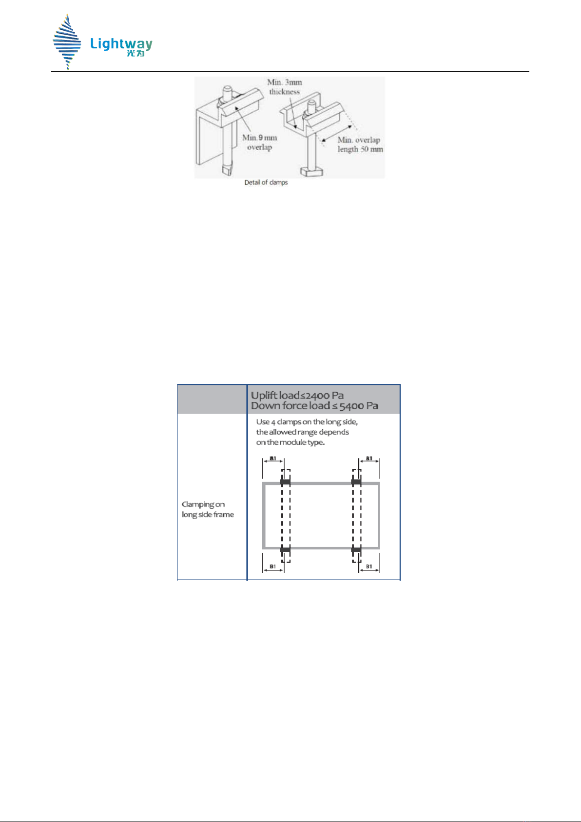
⊙Ensure that the installation method and supporting system of modules is strong enough to make the modules to
able to withstand all the load conditions. The Installer must provide the guarantee. The installation supporting
system must be tested by the third-party organization with the analysis ability of Static Mechanical, according to
the local national or international standards such as DIN1055 or equivalent standards.
⊙The Modules mounting structure must be made of durable, corrosion-resistant and UV-resistant material.
⊙Modules must be securely attached to the mounting structure.
⊙In regions with heavy snowfall in winter, select the height of the mounting system. So that the lowest edge of
the Modules is not covered by snow for any length of time. In addition, ensure that the lowest portion of the
Modules is placed high enough so that it is not shaded by plants or trees or damaged by flying sand.
⊙In case of installed on metal sheet roof, flush mounting is recommended. In case of installed on concrete roof,
the module could be tilted and a minimum of 10 degrees tilt angle should be follow for cleaning.
⊙Do not attempt to drill holes in the glass surface and the frames of the Modules .Before installing Modules on a
roof, ensure that the roof construction is suitable. In addition, any roof penetration required to mount the
Modules must be properly sealed to prevent leaks.
⊙Always keep the back sheet of the module free from foreign objects or structural elements, which could come
into contact with the module, especially when the module is under mechanical load.
⊙Please wear special labor protection gloves to avoid leaving fingerprints and perspiration stains and other dirt
on glasses. Regularly replace the dirty gloves in time.
⊙For module,external factors may lead the result such as thermal expansion and contraction, the same matrix is
recommended to reserve a certain distance between any two modules,at least 20mm.
⊙There are three colors in Lightway modules, light blue, blue and dark blue. In order to have a beautiful visual
effect, please install modules with the neighboring color. Light blue and dark blue should not be installed together.
⊙Please keep the connectors in tough while installing module. The cable should keep a certain length to ensure
that the both ends of cable have no stress.
When mounting modules in snow⊙-prone or high-wind environments, special care should be taken to mount the
modules in a manner that provides sufficient design while meeting local code requirements.
Product identification
Each module has two labels providing the following information:
Nameplate: describes the product type; rated power, rated current, rated voltage, open circuit voltage, short
circuit current, all as measured under standard test conditions; dimension etc. The maximum system voltage is

Lightway PV Modules, Installation Manual, Page 4/36
www.lightwaysolar.com
1500V volts DC and is shown on the nameplate. Maximum fuse rating is also shown.
Barcode: each individual module has a unique serial number. The first digit is the workshop code,the second and
third digits are the module specifications code, the 4th and 5th digits are the year code, the 6th and 7th digits are
the month code, the 8th and 9th digits are the Purchase Order number, the last four digits are the production
running series NO., for example, 2121306120011
2-- means the module was made in the No. 2 workshop.
12-- means the module specification is 1640*990*40.
1306-- means the module was made in June 2013.
12-- means the Purchase Order NO. is 12.
0011-- means the production running series NO. of the module is 0011.
There is only one barcode on module. It is permanently attached to the interior of the module visible when
viewing from the front of the module. This bar code is inserted at the beginning of laminating.
Typical serial number barcode label
Transport and Handling
Lightway PV modules must be transported in the supplied packaging Installation only and kept in the packaging
until they are ready to be installed. Protect pallets against movement and exposure to damage during
transportation. Secure pallets from falling over. Do not exceed the maximum height of pallets to be stacked, as
indicated on the pallet packaging. Store pallets in a cool and dry location until the PV modules are ready to be
unpackaged.
Lightway PV modules are heavy, and should be handled with care. PV modules shall be handled at the frame;
never use the junction box or cables as a grip. Do not exert mechanical stress on the cables. Never step on PV
modules or drop or place heavy objects on them. Be careful when placing PV modules on hard surfaces, and
secure them from falling. Broken glass can result in personal injury. PV modules with broken glass cannot be
repaired and must not be used. Broken or damaged PV modules must be handled carefully and disposed of
properly.
When unpacking PV modules from the Lightway supplied packaging, first remove the pallet lid (after removing
securing straps, if provided). Remove PV modules once at a time by sliding them up the channel in the package.
You may need to secure the remaining PV modules in the pallet packaging to prevent them from falling over.

Lightway PV Modules, Installation Manual, Page 5/36
www.lightwaysolar.com
Check PV modules for damage due to transportation before they are installed; do not install damaged modules.
Contact the company you purchased the Lightway PV modules from in order to obtain information on making
claims for defective PV modules.
PV module surfaces are susceptible to damage that could affect the performance or safety of the PV module; do
not damage or scratch the PV module surfaces, and do not apply paint or adhesive to any of the surfaces,
including the frame. For your safety, do not disassemble or modify Lightway PV modules in any way. Otherwise
may degrade performance or cause irreparable damage and will void any applicable warranties.
If it is necessary to store PV modules prior to installation, the PV modules should remain inside the packaging and
protected from exposure that could compromise the durability of the packaging.
Selecting the location
• Select a suitable location for installation of the module.
• The module should be facing true south in northern latitudes and true north in southern latitudes for best
power production.
• For detailed information on the best elevation tilt angle for the installation, refer to standard solar
photovoltaic installation guides or a reputable solar installer or systems integrator
• The module should not be shaded at any time of the day.
Selecting the proper support frame
• Always observe the instructions and safety precautions included with the support frame to be used with the
module.
• No attempt must be made to drill holes in the glass surface of the module. To do so will void the warranty.
• Do not drill additional mounting holes in the frame of the module. Doing so will void the warranty.

Lightway PV Modules, Installation Manual, Page 6/36
www.lightwaysolar.com
Installation method
Bolt Mounting:
Modules must be securely attached to the mounting structure using all of the mounting points for installation.
Installation diagram(60cells) Detail of a bolt mounting attachment
⊙1650×990×40series,1650×992×40 series, 1640×990×40series,1640×992×40 series, 1680×992×40,1680×990×40
series , 1665×1002×40series,1684×1002×40series,1845×1002/998×40series,shall be installed with a rack structure
by using 8 sets of an M6 screw ,two flat washers , a split washer and an M6 nut;
⊙1960×990×40series,1956×990×40series, 1960×992×40 series,1956×992×40 series,2006×992×40series,
2006×990×40series,1979×1002×40series,2008×1002×40series,contain two mounting hole dimensions; IF the
mounting hole size is 6.5x11, shall be installed with a rack structure by using 8 sets of an M6 screw, two flat
washers, a split washer and an M6 nut; IF the mounting hole size is 9x14, these series also can be installed with a
rack structure by using 8 sets of an M8 screw, two flat washers, a split washer and an M8 nut;
⊙1650×990×35series,1650×992×35series,1640×990×35series,1640×992×35series,1680×992×35series,
1680×990×35series, 1665×1002×35series,1684×1002×35series,shall be installed with a rack structure by using 4
sets of an M8 screw,two flat washers,a split washer and an M8 nut;
⊙the material of the screw, washers and nut is stainless steel, and the torque of M6 screw assembly is3-9 N•m,
the torque of M8 screw assembly is 16-20 N•m.The recommended standoff height is 11cm;
⊙About the mechanical loading test,the design loading is 3600Pa for the front side,and 1600Pa for the back side.
The safety factor are All 1.5 times.
Clamp Mounting:
The mounting method has been qualified by Lightway and certified by TUV. Follow mounting guide-lines
recommended by the mounting system supplier. Each module must be securely fastened at a minimum of 4 points
on two long side frames. Install and tighten the module clamps to the mounting rails using the torque stated by
the mounting hardware manufacturer. System designer and installer are responsible for load calculations and for
proper design of support structure. Lightway warranty may be void in cases where improper clamps or unsuitable
installation methods are found.
About the mechanical loading test,the design loading is 3600Pa for the front side,and 1600Pa for the back side.
The safety factor are All 1.5 times.

Lightway PV Modules, Installation Manual, Page 7/36
www.lightwaysolar.com
When installing inter-modules or end type clamps, take measures so as
⊙Not to bend the module frame
⊙Not to touch or cast shadow on the front glass
⊙Not to damage the surface of the frame
⊙To ensure the clamps overlap the module frame by at least 9 mm.
⊙To ensure the clamps overlap length is at least 50 mm.
Clamp material should be anodized aluminum alloy. Floating type clamps are not authorized. Clamp positions are
of crucial importance for the reliability of the installation, the clamp centerlines must only be positioned within
the ranges indicated in table below, depending on the configuration and load. For configurations where the
mounting rails run parallel to the clamps installation side, precautions should be taken to ensure the module
frame (C-shape) overlap the rail by 15mm or More.
If other mounting means are employed. Please refer to the drawings as below in detail.

Lightway PV Modules, Installation Manual, Page 8/36
www.lightwaysolar.com
Electrical installation
⊙While connected in parallel,the output current is equal to the sum of current of each string. Use a Fuse in each
string of module; Please refer to the application requirements locally. Recommended maximum parallel module
configurations: Fuse rating/(Isc*1.25).
Always use the same type of module in a PV system. While connected in series, voltage of each string should
below maximum system voltage. Recommended maximum series module configurations:1500V/(1.25*Voc) .
The cross section area of cable and the capacity of connector must be selected to suit the maximum system short
circuit current (Recommended cross section area of cable is 4mm²for a single module and rated current of a
connector is larger than 10A),otherwise the cable and connector will be overheated under large current. Please
pay attention:the temperature limit of cable is 85℃).
⊙Functional earth the negative pole of the system will prevent the PID effect from happening. However, the
earthing application need the galvanic isolation between the DC and the AC. This is normal realized by using a
isolation transformer.
Grounding
⊙All module frames and mounting racks must be properly grounded in accordance with local and national
electrical codes. The frame rails have pre-drilled holes marked with a grounding sign. These holes should be used
for grounding purposes and must not be used for mounting the PV modules. Do not drill additional holes into the
frame .The following grounding methods are available:
⊙A grounding screw assembly must be attached at a designated grounding holes location using only stainless
steel hardware. Insert a M5 stainless steel screw first through spring washer, cup washer with a copper wire, flat
washer, star washer, and then through the grounding hole on the frame, flat washer, spring washer, at last tighten
them with the M5 nut.

Lightway PV Modules, Installation Manual, Page 9/36
www.lightwaysolar.com
Module Terminations
A junction box as terminal enclosure is equipped for electrical connections on lightway PV modules. Please contact
your local dealer with questions regarding other electrical connections for modules. J-box configuration and
description of terminals (for reference) .Modules equipped with one j-box contain terminals for both positive and
negative polarity, and bypass diodes. The junction box meet the IEC 62790, the cable meet the EN 50618, and
the connector meet the IEC 62852.
Please take the cable length of the module into consideration before designing the wiring layout.
Sketch Map of junction box
Bypass Diodes
When the modules in series strings are shaded partially, it may cause a reverse voltage across cells or modules,
because the current from other cells in the same series is forced to flow through the shaded area, and then
undesirable heating may occur. The use of a diode to bypass the shaded area can minimize both heating and
reduction of array current. All lightway PV modules are equipped with factory installed bypass diodes. The
factory-installed diodes provide proper circuit protection for the systems within the specified system voltage, so
that you don’t need any other additional bypass diodes. Contact your authorized lightway distributor or dealer for
proper diode type, if necessary to add or change diodes due to system specification.
Testing, commissioning and troubleshooting
Test all electrical and electronic components of the system before using it. Follow the instructions in the guides
supplied with the components and equipment.
Testing modules connected in series before they are connected to system
⊙Check the open-circuit voltage of every series module by a digital multimeter. The measured values should

Lightway PV Modules, Installation Manual, Page 10/36
www.lightwaysolar.com
correspond to the sum of the open-circuit voltage of the individual module. You will find the rated voltage in the
technical specifications of the type of the module used. If the measured value is significantly lower than the
expected value, please proceed as described under “Troubleshooting an excessively low voltage”.
⊙Check the short-circuit current of every series circuit. It can be measured directly by a digital multimeter
connected in the two terminals of series circuit or module, or with any load such as PV illumination to make a
rough measurement. Attention, the rated scale of the ammeter or the rated current of load should more than 1.25
times of the rated short-circuit current of series module. You will find the rated current in the technical
specifications of the type of module used. The measured value can vary significantly, depending on weather
conditions, the time of day and shading of the module.
Trouble shooting low voltages
Identify the commonly low voltage and excessively low voltage. Commonly the low voltage mentioned here is the
decrease of open-circuit voltage of the module, which is caused by the temperature rising of solar cells or lower
irradiance. Excessively low voltage is typically caused by improper connections at the terminals or defective bypass
diodes.
Maintenance
General
Lightway recommends that PV systems be periodically inspected by the installer, or other qualified person.
The purpose of the PV system inspection is to ensure that all system components are functioning properly. At a
minimum, this inspection should confirm the following:
– All cables and connector attachments are undamaged and properly secured
– No sharp objects are in contact with the PV module surfaces
– PV modules are not shaded by unwanted obstacles and/or foreign material
– Mounting and grounding components are tightly secured with no corrosion
Defects should be addressed immediately.
Cleaning
Over time, dirt and dust can accumulate on the glass surface of the module, reducing its power output. Lightway
recommends periodic cleaning of PV modules to ensure maximum power output, especially in regions with low
precipitation.
⊙In order to reduce the potential for electrical and thermal shock, Lightway recommends cleaning PV modules
during early morning or late afternoon hours when solar radiation is low and the modules are cooler, especially in
regions with hotter temperatures.
⊙Never attempt to clean a PV module with broken glass or other signs of exposed wiring, as this presents a shock
hazard.
⊙Clean the glass surface of the PV modules with a soft brush using soft, clean water with a recommended
pressure less than 690kPa, which is typical of most municipal water systems. Water with high mineral content may
leave deposits on the glass surface and is not recommended.
⊙Lightway PV modules may contain a hydrophobic anti-reflective coating on the glass surface to enhance power
output and reduce dirt and dust buildup. In order to avoid module damage, do not clean PV modules with a power

Lightway PV Modules, Installation Manual, Page 11/36
www.lightwaysolar.com
washer or pressure washer. Do not use steam or corrosive chemicals to facilitate the cleaning of modules. Do not
use aggressive tools or abrasive materials that could scratch or damage the glass surface. Failure to comply with
these requirements may adversely affect the PV module performance.
⊙Lightway PV modules are designed to withstand high snow loads. However, if removing snow is desired to
enhance production, use a brush to gently remove snow. Do not try to remove frozen snow or ice from PV
modules.
Recyling
Lightway has got the WEEE certification from TUV Rheinland,WEEE is a instruction which is stipulated by EU for
the waste electrical and electronics recycling.
Meaning of crossed –out wheeled dustbin:
⊙Do not dispose of electrical appliances as unsorted municipal waste, use separate collection facilities.
⊙Contact your local government for information regarding the collection systems available.
⊙If electrical appliances are disposed of in landfills or dumps, hazardous substances can leak into the
groundwater and get into the food chain, damaging your health and well-being.
⊙When replacing old appliances with new ones, the retailer is legally obligated to take back your old appliance
for disposals at least free of charge.
Disclaimer of Liability
⊙Because the use of this manual and the conditions or methods of installation, operation, use and maintenance
of photovoltaic (PV) product are beyond Lightway’s control, Lightway does not accept responsibility and expressly
disclaims liability for loss, damage, or expense arising out of or in any way connected with such installation,
operation, use or maintenance.
⊙No responsibility is assumed by Lightway for any infringement of patents or other rights of third parties, which
may result from use of the PV product No. license is granted by implication or otherwise under any patent or
patent rights.
⊙The information in this manual is based on Lightway’s knowledge and experience and is believed to be reliable;
but such information including product specification (without limitations) and suggestions do not constitute a
warranty, expresses or implied. Lightway reserve the right to change the manual, the PV produce, the
specifications, or product information sheets without prior notice.

Lightway PV Modules, Installation Manual, Page 12/36
www.lightwaysolar.com
If it is inconsistent between the different languages, the English version shall be prevail.

Lightway PV Modules, Installation Manual, Page 13/36
www.lightwaysolar.com
REAR AND SIDE VIEW DIMENSIONS (UNITS: mm)
(1956/1960)×(990/992)×40 Multi-poly, Mono-poly Series

Lightway PV Modules, Installation Manual, Page 14/36
www.lightwaysolar.com

Lightway PV Modules, Installation Manual, Page 15/36
www.lightwaysolar.com
1650×(990/992)×40 Multi-poly , Mono-poly Series

Lightway PV Modules, Installation Manual, Page 16/36
www.lightwaysolar.com
1640×(990/992)×40 Multi-poly , Mono-poly Series

Lightway PV Modules, Installation Manual, Page 17/36
www.lightwaysolar.com
1650×(990/992)×35 Multi-poly , Mono-poly Series

Lightway PV Modules, Installation Manual, Page 18/36
www.lightwaysolar.com
1640×(990/992)×35 Multi-poly , Mono-poly Series

Lightway PV Modules, Installation Manual, Page 19/36
www.lightwaysolar.com
2006×(992/990)×40 Multi-poly
This manual suits for next models
169
Table of contents
Popular Solar Panel manuals by other brands

Tamarack Technologies
Tamarack Technologies UNI-RV40 installation manual

Projecta
Projecta SPM80K Operation manual

GH Solar
GH Solar GHxxxP-36 Series installation manual

UMA Solar
UMA Solar Heliocol Series installation manual

AGRO ELECTRO
AGRO ELECTRO 0090 user manual

HTP
HTP HP-30SC Installation, start-up, maintenance, parts, warranty