iv LY Installation and Maintenance for LY 1001, LY 2001 and LY 3001 LMAIM1501
7 Maintenance 7-1
7.1 Lubrication 7-1
7.1.1 Lubrication Inspection 7-1
7.1.2 Factor Lubricant 7-1
7.2 Minimum Lubricant Qualities Required 7-1
7.3 Disassembl and Reassembl 7-2
7.3.1 LY 1001 Disassembl 7-2
7.3.2 LY 1001 Reassembl 7-3
7.3.3 LY 2001/3001 Disassembl 7-5
7.3.4 LY 2001/3001 Reassembl 7-7
7.4 Troubleshooting 7-9
8 Parts Lists 8-1
9 How to Order Parts 9-1
10 Regulatory Information 10-1
Figures
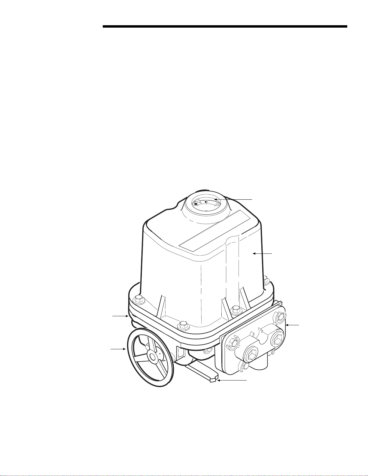
Figure 2.1 – LY Actuator 2-1
Figure 3.1 – LY Nameplate 3-1
Figure 5.1 – Torque Nut and Retaining Drive Ring Removal from an LY 1001 5-1
Figure 5.2 – LY Ke wa Locations 5-2
Figure 5.3 – LY 1001, 2001, and 3001 Torque Drive Nut Orientation 5-3
Figure 5.4 – Removing Control Cover and Conduit Pipe Plugs 5-4
Figure 5.5 – Grounding Lug Location 5-5
Figure 5.6 – Reversing Torque Switch Wiring 5-7
Figure 5.7 – Limit Switch Setting Nut 5-8
Figure 5.8 – Setting CLOSE Limit Cam 5-9
Figure 5.9 – Setting OPEN Limit Cam 5-10
Figure 5.10 – Mechanical Stop Set Screw Adjusted to Torque Drive Nut
Contact Point on LY 1001 5-11
Figure 5.11 – Mechanical Stop Screw Adjustment on LY 2001 and 3001 5-12
Figure 5.12 – Aligning MDPI (Mechanical Dial Position Indicator) 5-13
Figure 5.13 – Potentiometer Calibration Components 5-14
Figure 6.1 – Standard Actuator/Three-Phase 6-2
Figure 6.2 – Three-Phase with Control Package 6-3
Figure 6.3 – Standard Actuator/Single-Phase 6-5
Figure 6.4 – Single-Phase with Control Package 6-6
Figure 6.5 – LY 1001 Cover and Associated Parts 6-7
Figure 6.6 – LY 1001 Top Plate and Associated Parts 6-9
Figure 6.7 – LY 1001 Housing and Associated Parts 6-10
Figure 6.8 – LY 2001/3001 Cover and Associated Parts 6-11
Flow Control Division
Limitorque Actuation S stems