Key Code
The access to the installation level is protected against
unauthorized use by a key code. This will enable you
to change settings described in this manual.
This operating level should only be accessed by a
heating contractor or a trained operator.
Accessing the installation level.
Key Code 3
7
Key Code
• Press and release the “AUT” button. Button
is located adjacent to cover flap.
• Press and hold down the “INS”
button.
• Insert a pointed object into the hole
to the right of the “INS” button. Release
the “INS” button and remove the pointed
object from the hole.
• The control automatically
reverts back to previous operation if no
entries are made within 20 seconds.
• Different settings become accessible
by repeatedly pressing the “INS” button.
The display will indicate the current
setting. The value of each setting is
changed by turning the dial.
AMERICAN
INS O
SETTING THE LANGUAGE TO AMERICAN
• Enter the key code
• Turn dial until “American” appears.
• Automatic operation is resumed after
20 seconds.
2 Program Overview
6
Possible settings for the installation level.
The following settings allow the heating contractor to
customize the Ecomatic HS 2102 control for the
particular application.
1. Language:
Factory Setting: American
Other Languages: Deutsch, English,
Español, Italiano, etc.
2. Temperature Scale:
Factory Setting: Fahrenheit
Optional Selection: Celsius
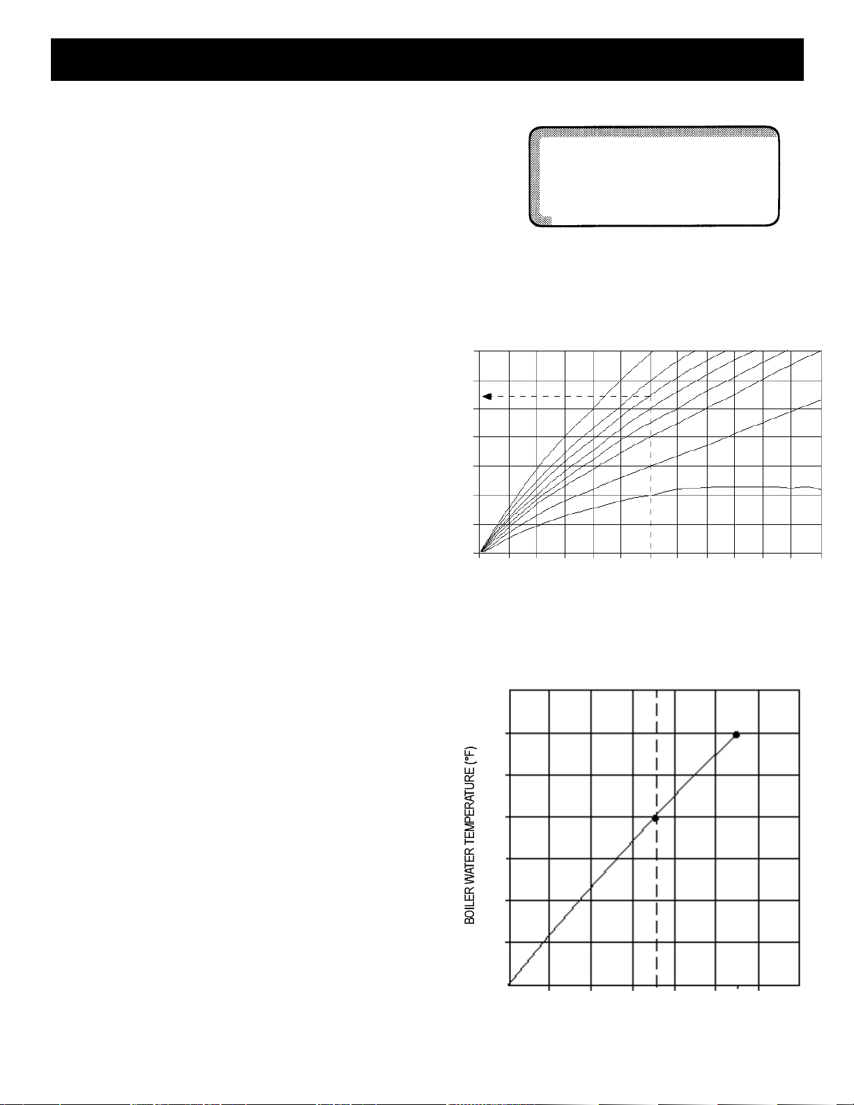
3. Heating curve-REF TEMP:
Factory Setting: 167°F (75˚ C)
Range: 122°F to 194°F (50°C to 90°C)
4. Freeze protection temperature-FREEZTEMP:
Factory Setting: 34°F (1°C)
Range: 14°F to 50°F (-10°C to 10°C)
5. Room Sensor - BFC:
Factory Setting: Off
Option: On
6. Compensation temperature-ROOM COMP:
(only with room sensor)
Factory Setting: 5°F (3°C)
Range: 0°F to 18°F (0°C to 10°C)
7. Setback modes:
Factory Setting: Outside Air Setback
Options: Setback
Room Setback
Boiler Off
8. Minimum boiler water temperature-MIN TEMP:
Factory Setting: 50°F (10°C)
Range: 50°F to 104°F (10°C to 40°C)
9. Maximum boiler water temperature-MAX TEMP:
Factory Setting: 185°F (85°C)
Range: 149°F to 194°F (65°C to 90°)
10. Flue Gas Sensor-FLUE GAS:
Factory Setting: Off
(Not available in the USA)
11. Clock recalibration-TIM ADJ:
Factory Setting: 0 Sec/Day
Range: -59 to 59 Sec/Day
12. Room temperature shift-OFFSET:
Factory Setting: 0
Range: -9°F to 9°F (-5°C to 5°C)
13. Diagnostic Test Features:
Relay Test
LCD Test
Heating curve display
Version number