8
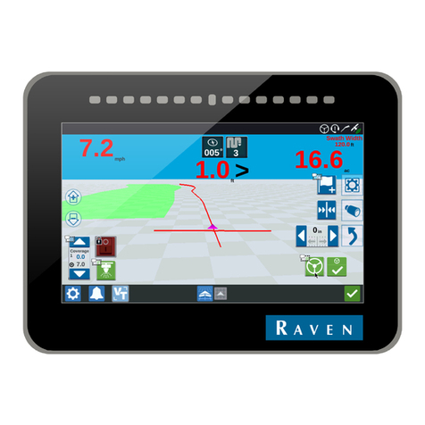
4. The GPS Status status indicator displays the status of GPS reception and the
currently selected correction source on the Guidance screen. See the “GPS
Status Indicator” section on page 2 for more information.
5. Touch the Display Mode icon to toggle the day or night modes for the guidance
screen display.
6. This area displays the Speed or Course Over Ground (COG). Touch this area
to toggle the information displayed.
7. The Distance to Swath display shows the distance and direction to the
displayed Guidance path.
8. The SmarTrax Status is displayed if an optional SmarTrax or SmartSteer
system is connected to the field computer. This indicator appears green if the
system is engaged or red if the system is disengaged.
If the CAN SmarTrax or SmartSteer node is installed, the SmarTrax engage/
disengage icons will be displayed in the lower, right corner of the guidance
display. Refer to the SmarTrax and SmartSteer Installation and Operation
Manual for more information.
9. The current status of Wireless Communication is displayed on the guidance
screen. See the “Wireless Communications Status” section on page 3 for more
information.
10.The Product Rate Display shows target and actual application rates as well
as indicates the selected product.
Touch the name of a product to toggle the selected product or touch in the rates
area to access the In Job Product Configuration screen. Additional display
options may be activated on the In Job Product Configuration screen.
11.Touch the Rate Bump buttons to increase or decrease the rate of the selected
product. When operating in Automatic control mode, the rate bump buttons will
increase or decrease the target rate. In Manual control mode, these buttons will
adjust the actual application rate.
12.Touch the AccuBoom Override to override all sections On for the selected
On-Override time. See the “AccuBoom” section on page 11 for details.
13.The AutoBoom Status Indicator is displayed if an optional AutoBoom system
is connected to the field computer. See the “AutoBoom” section on page 13 for
more information regarding the AutoBoom Status Indicator.
14.The Section Status Display shows information for each configured section.
Active sections appear green while sections currently disabled (or toggled off)
appear in white.
15.The Swath Information displays the number of the current swath when using
the Straight Line, Fixed Contour, or Pivot patterns. When using the Enhanced
Last Pass pattern, this area displays LAST.
16.Touch the Nudge Settings icon to to display the In-Job Nudge Settings
screen. Use this screen to set the active nudge value and enable the on-screen
nudge controls.
17.Use the Zoom In and Out icons to change the level of detail shown on screen.
18.Touch the Alternate Guidance Pattern button to toggle the pattern used to
provide guidance for the job in progress.
19.Access the Menu to display additional tools and features of the job in progress.
The Menu contains the tools for recording a field boundary and creating or
editing a Guidance Path.

