CorroVenta HomeVision Pro User manual

HOMEVISION® PRO
Control System for VentoVind™ and crawl space
dehumidifiers CTR STD-TT and CTR 300TT2
USER MANUAL

HomeVision® Pro
© Corroventa Avfuktning AB
2021.02
1 (44)
Contents
Area of use..................................................................................................................................................3
Manufacture directive ................................................................................................................................4
Safety information ......................................................................................................................................5
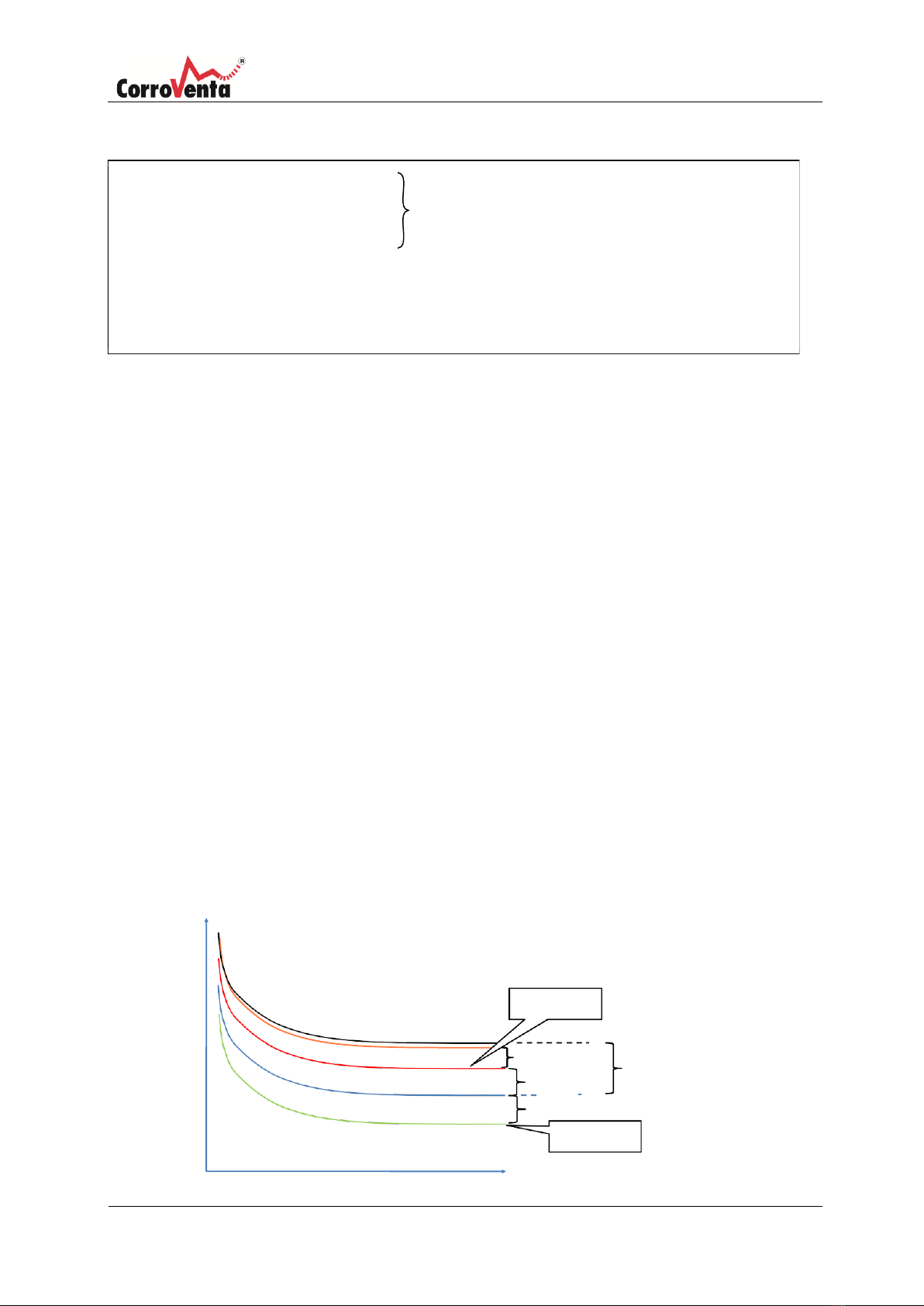
Relative humidity and its impact on materials ...........................................................................................6
Controlling humidity ...................................................................................................................................6
Fixed RH regulation.....................................................................................................................................6
Mould index regulation...............................................................................................................................7
Delivery check.............................................................................................................................................8
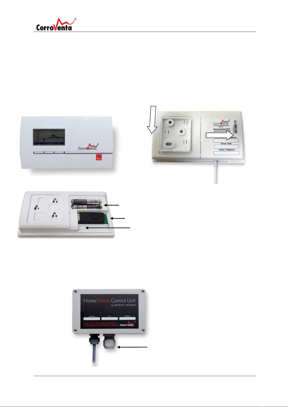
Product overview........................................................................................................................................9
Control unit.................................................................................................................................................9
Control unit dehumidifier ...........................................................................................................................9
Control unit VentoVind™ ..........................................................................................................................10
Installation ................................................................................................................................................11
Installation of control unit and connection of control panel for crawl spaces.........................................11
Installation of control unit and connection of control panel for VentoVind™ .........................................12
Installation of control panel......................................................................................................................15
HomeVision® Pro ......................................................................................................................................16
Status view Crawl space............................................................................................................................18
Status view VentoVind™...........................................................................................................................19
Overview view...........................................................................................................................................20
Setup view.................................................................................................................................................21
Statistics view............................................................................................................................................21
Set date and time......................................................................................................................................22
Connecting a new unit..............................................................................................................................23
Remove the USB stick ...............................................................................................................................24
Selecting language ....................................................................................................................................25
Service status –Reset service counter .....................................................................................................25
System status............................................................................................................................................26
Diagnostics –Test of radio connection.....................................................................................................27
Diagnostics –Test of crawl space dehumidifier........................................................................................28
Diagnostics –VentoVind™, See Sensor data.............................................................................................29
Diagnostics –VentoVind™, Fan test .........................................................................................................30
Diagnostics –VentoVind™, Damper test ..................................................................................................31
See overview of settings for all units, Crawl space...................................................................................32
See configuration overview for all units, VentoVind™ .............................................................................33

HomeVision® Pro
© Corroventa Avfuktning AB
2021.02
2 (44)
Reconfigure unit (by regulation parameters), Crawl space......................................................................34
Reconfigure unit (by regulation parameters), VentoVind™ .....................................................................35
Resetting to factory default......................................................................................................................37
Remove unit..............................................................................................................................................38
Alarms and service reminders ..................................................................................................................39
Interpreting the USB log ...........................................................................................................................41
Maintenance and service..........................................................................................................................42
Troubleshooting........................................................................................................................................43
Technical data...........................................................................................................................................44

HomeVision® Pro
© Corroventa Avfuktning AB
2021.02
3 (44)
Area of use
HomeVision® Pro has been developed and designed for wireless control and monitoring of
Corroventa CTR STD-TT and CTR 300TT2 crawl space dehumidifiers as well as VentoVind™, adaptive
ventilation of cold attic spaces.
There are two versions of control unit, one for crawl spaces and one for VentoVind™ but the control
panel is common and compatible to both.
For easy monitoring, the control panel presents operating statistics in the form of graphics e.g.
average temperature and average relative humidity. It also shows any operational alarms and
service reminders such as filter replacement. The control panel also stores operational data on a
USB stick in a format which can be read in Excel or corresponding software.
Each control panel can connect up to 8 control units so even if the property requires more
than one dehumidifier or perhaps both crawl space dehumidification and VentoVind™, all
control and monitoring occurs from the same place, as long as there is sufficient radio
reception.
•Monitoring crawl space climate, temperature and humidity
•Monitoring and controlling VentoVind™
•Operational indicators and operational alarms
•Easy to install –wireless control panel
•Service reminders
•Graphic display with simple user interface
•Expandable –the control panel can control up to eight control units.

HomeVision® Pro
© Corroventa Avfuktning AB
2021.02
4 (44)
Manufacture directive
HomeVision® Pro has been electrical safety tested and EMC tested. HomeVision® is CE labelled.
Disclaimer
•
Incorrect installation and/or incorrect handling can cause property damage as well as injury.
•
The manufacturer assumes no liability for damage arising as a result of failing to follow these
instructions, not using the machine as intended. Such damage is not covered by the
warranty.
•
The warranty applies to damage to the machine caused by material or manufacturing
defects and does not cover consequential failure.
•
The warranty does not apply to consumables or to normal wear.
•
It is the responsibility of the purchaser to inspect the goods upon delivery and to ensure its
function according to the instructions in the manual during use.
•
Changes or modifications to the machine must not be performed without written
permission from Corroventa Avfuktning AB.
•
The product, technical data and/or installation and operating instructions are subject
to change without notice.
•
These user instructions contain information protected by copyright laws. No part of this
document may be reproduced, stored in an information storage system or transmitted in
any way or by any means without Corroventa AB's written consent.
Any comments regarding the content of this document must be sent to: Corroventa
Avfuktning AB Tel: +46 (0)3637 12 00
Mekanikervägen 3 E‐mail mail@corroventa.se
SE-564 35 Bankeryd, Sweden

HomeVision® Pro
© Corroventa Avfuktning AB
2021.02
5 (44)
Safety information
This device is not intended for use by persons with reduced physical, mental or sensory impairments
which affect their ability to operate or understand the equipment nor other persons lacking the
necessary skills or experience, unless supervised or instructed by another person with responsibility
for their safety.
Children may only use the device under the supervision of an adult to ensure that the device is
not used as a toy.
Electrical installations carried out in connection with dehumidifier and HomeVision® installation
must be done by a qualified electrician in accordance with local and national regulations.
1.
Read and observe the safety information in the manual for the dehumidifier to be installed
and/or used.
2.
Incorrect settings of HomeVision® or VentoVind™ control system can cause damage to the property
and/or the equipment as well as excessive energy consumption.
3.
HomeVision Control unit for crawl space dehumidifier is connected by cable to the dehumidifier and is
placed in the crawl space at approximately half the height of the space in such a way that it is not
affected by:
a.
Dry air from the dehumidifier.
b.
Wet air from the dehumidifier.
c.
Radiation from surfaces hotter than the ambient air.
d.
Radiation from surfaces colder than the ambient air.
4.
VentoVind™ control unit is connected to grounded, 230V socket with 10A fuse, maximum 16A
fuse.
5.
VentoVind™ sensors are installed as follows:
a.
The indoor sensor is positioned at approximately half the height of the attic space and
approximately in the middle of the space so that its measurement values are
representative of the space.
b.
The outdoor sensor is positioned on the gable end pointing north protected from sunlight and
rain.
6.
Position the control panel:
a.
in a hall or similar area that is usually frequented so that operational alarms from the
system are quickly detected.
b.
so that small children cannot access it, thus preventing unintentional setting changes.
7.
Since the aim is to permanently supply the control panel via the supplied battery eliminator, do not
leave batteries in the control panel as many battery types and brands have a tendency to leak as
they age.
8.
Using electrical equipment in very damp or wet conditions can be dangerous. Do not operate the
dehumidifier if it or the Control unit is standing in water.
9.
Water must not come into contact with the dehumidifier's or HomeVision™ electrical components. If
it does, ensure that they are dried thoroughly before the system is used again.
10.
It is recommended that the wall socket that supplies the dehumidifier and thus also the control unit is
protected by a circuit breaker to minimise the risk of electric shock.
11.
Do not damage the cables. They must nor run through water or over sharp edges.
12.
HomeVision® and VentoVind™ must not be used with accessories other than those described in
this manual or approved by Corroventa Avfuktning AB.
Contact the supplier of this dehumidifier for further advice on the safety and use of the product.

HomeVision® Pro
© Corroventa Avfuktning AB
2021.02
6 (44)
Relative humidity and its impact on materials
All air contains a greater or less amount of moisture but we can’t see it with the naked eye until it
appears in the form of small water drops against a cold surface of metal or glass. However, before it
is visible, moisture is already causing problems by affecting materials and manufacturing processes,
causing corrosion and growth of micro-organisms. In Scandinavia, in particular, one must always
assume that it is humid due to large areas of water in the thousands of lakes and surrounding seas.
Air humidity is measured and is often given in relative humidity (%RH), which is a measure of how
much water the air contains in relation to how much it can maximally contain at a given
temperature. The higher the temperature, the more water the air can hold but it is the relative
humidity which is calculated, and which must be controlled.
At 100% RH the air is saturated and the moisture falls in the form of small water droplets. Steel
corrodes at 60% RH and at 70% RH there is a risk of mould. A rule of thumb is that 50% RH is a good
climate for most materials but here in Scandinavia, it is rarely so low. The annual average value in
most places is instead around 80% RH and can be equally high in both summer and winter.
Controlling humidity
Installing the dehumidifier according to the instructions and manual, provides the conditions for
establishing and maintaining a climate that prevents rot, mould and bad odours in the space.
HomeVision® with its wireless control panel offers easy and convenient monitoring of the climate
from the accommodation and allows the user to select between Fixed RH regulation and MGI
Regulation (mould index regulation).
Fixed RH regulation
With the regulation principle Fixed RH, a setpoint value for the humidity is set, a value to control
around. Furthermore, an upper and a lower hysteresis are set as well as an alarm limit that defines
the alarm level at which, if reached, an alarm appears on the control panel. The chart below is not to
scale, it has the sole purpose of clarifying the principle and parameters.
Alarm level
Setpoint value
Temperature
%-
RH
Dehumidification on
Alarm +%RH
Hysteresis Upper/Lower:
Dehumidification off

HomeVision® Pro
© Corroventa Avfuktning AB
2021.02
7 (44)
To help understand this principle here is an example that can be studied in parallel with the chart:
Setpoint, %RH: 65%
Hysteresis Upper/Lower: + 4%, -4%
Activation: Setpoint value + Hysteresis Upper = 65% +
4% = 69% Off: Setpoint value + Hysteresis Lower = 65% -
4% = 61%
Alarm, +RH: 10% Added to the activation level to give alarm level.
Alarm level = Setpoint value + Hysteresis Upper + Alarm =
65% + 4% + 10 % = 79%
As seen in the example , the setpoint value must not be mixed up with the highest permitted level
because the setpoint value exceeds the corresponding Hysteresis Upper before the dehumidifier is
activated. At high moisture load, relative humidity can increase slightly before the dehumidifier
makes an impact and the relative humidity in the crawl space begins to drop. The result of this is
that the setpoint value, if not entirely accurate, can be seen as an upper limit for the humidity's
average value over a longer period, and for this there must be a margin, greater than the upper
hysteresis, for the humidity at which damage occurs.
The reason the user is given the option to influence hysteresis is that it must be possible to adjust
the system for optimum operating profile in any given location. Too narrow an interval, the range
given by the upper and lower hysteresis provides many starts and stops of the dehumidifier and
therefore an increase in equipment wear. Too great a range means that, at each activation, the
system drives down the humidity unnecessarily low resulting in increased energy consumption.
Mould index regulation
HomeVision® Pro permits, in addition to traditional, fixed, regulation of the relative humidity,
application of mould index regulation, MGI regulation. This regulation method uses the fact that the
mould growth, in addition to the humidity is also temperature dependent. At lower temperatures,
higher humidity can be tolerated without risking mould growth and the positive result of this is of
course the potential to save energy.
The regulation principle, as with the energy saving aim, implemented in HomeVision® Pro can be
clarified with the help of the chart below. The chart is not to scale but is intended only to clarify
the principle and actual parameters.
%-RH
Dehumidification on
Mould index curve
Alarm, +%RH
Safety margin
Dehumidification off
Temperature
RH-MGI
Hysteresis Lower
Hysteresis Upper

HomeVision® Pro
© Corroventa Avfuktning AB
2021.02
8 (44)
Actual MI = The humidity that forms the lower limits of mould growth for the actual
temperature.
The upper curve, the mould index curve, is programmed in HomeVision® and is therefore not
something that is affected by user settings. The user is asked instead to specify the desired safety
margin, upper and lower hysteresis and alarm limit whose meanings are explained using the
following example.
Safety margin, %RH:
‐15%
Activation:
Actual MI–Safety margin + Hysteresis Upper =
Hysteresis Upper/Lower:
+ 4%, ‐4%
= Actual MI –15% + 4%
Off:
Actual MI –Safety margin –Hysteresis Lower =
= Actual MI–15% - 4%
Alarm, +%RH:
10%
Added to the activation level to give alarm
level. Alarm level:
Actual MI –Safety margin + Hysteresis Upper + Alarm=
= Actual MI –15% + 4% + 10 %
The principles are recognised from Fast RH regulation, but instead of a constant setpoint the
safety margin is determined against the mould index. When it comes to hysteresis and the
alarm, these work in the same way as for Fixed RH regulation.
As the reader will certainly have established, the relative humidity can be allowed to rise slightly
higher in the lower temperature range,with the support of the mould index, and thus provide an
energy saving. At higher temperatures, both the fixed and mould index regulation methods overlap
and thus the power consumption is the same.
Delivery check
HomeVision® for crawl spaces is supplied with the following parts in the package:
Control unit for connection to CTR STD-TT
or CTR 300TT2
1 x
Control panel with USB stick
1 x
Battery eliminator for control panel
1 x
Batteries for control panel, AAA cells*
2 x
Manual
1 x
HomeVision® for VentoVind™ is supplied with the following parts in the package:
VentoVind™ Control unit
1 x
Control panel with USB stick
1 x
Battery eliminator for control panel
1 x
Batteries for control panel, AAA cells*
2 x
Manual
1 x
Outdoor sensor
1 x
Indoor sensor
1 x
*) To use the installed batteries, the plastic protection strip must be removed so that the battery terminals

HomeVision® Pro
© Corroventa Avfuktning AB
2021.02
9 (44)
come into contact with the panel. The batteries are intended for use during installation. During normal
operation, the control panel must be powered via the battery eliminator and the batteries removed from
the control panel to prevent leakage, which can occur in ageing batteries.
Product overview
Control unit
Display
window
2 x Batteries, AAA cells
USB stick
Connection for
AC adapter.
Control unit dehumidifier
The control unit is installed with the sensor downwards.
Sensor
Remove wall mounting downwards
Protective cover
Press the arrow symbol
down and slide the cover
to the right

HomeVision® Pro
© Corroventa Avfuktning AB
2021.02
10 (44)
Control unit VentoVind™
Control unit with sensors and control panel.
Sensors
Indoor and
outdoor

HomeVision® Pro
© Corroventa Avfuktning AB
2021.02
11 (44)
Installation
Installation of control unit and connection of control panel for crawl spaces
When the control unit is to be installed, also prepare the control panel by inserting its batteries
and take it with you to the crawl space. Comprehensive installation instructions can be found in
the enclosed installation manual for the dehumidifier. The following instructions are a brief
summary.
1.
Install the control unit, within the reach of the cable length to the dehumidifier, in a
location in the crawl space where its measurement values will be representative for
the surrounding climate by ensuring that:
•
The unit is positioned at approximately half the height of the crawl space.
•
The unit is not affected directly by the dehumidifier's dry air.
•
The unit is not affected by the dehumidifier's wet air.
•
Not affected by radiation from heat sources.
•
Not affected by radiation from surfaces colder than the ambient air.
The control unit is suspended in the cradle that is included in Mounting kit TT Multi with
the sensor facing down towards the ground. The cradle is secured according to the image
below.
2.
Connect the Control unit's cable to the dehumidifier and power the dehumidifier by
connecting the power cable. Continue to point 3. for connecting to the control panel

HomeVision® Pro
© Corroventa Avfuktning AB
2021.02
12 (44)
1.
3.
Installation of control unit and connection of control panel for VentoVind™
When the control unit is to be installed, also prepare the control panel by inserting its batteries and
take it with you to the attic. Comprehensive installation instructions can be found in the enclosed
installation manual for VentoVind™. The following instructions are a brief summary.
1.
Install the supplied brackets on the control unit. Tap in the pins to secure the mountings to the
control box. Then mount the control unit on a flat surface centrally and make sure it is easy to
access.
Install the fan and all mounting hardware. Mount the indoor sensor so that it is
representative of the ambient climate by ensuring that:
•
The sensor is positioned at approximately half the height of the attic space.
•
The sensor is not directly affected by the fan's incoming air.
•
The sensor is not affected by radiation from heat sources.
•
The senor is not affected by radiation from surfaces colder than the ambient air.
Install the outdoor sensor in a location outdoors that is protected from direct sunlight and rain,
preferably under the roof overhang on the north or west gable end or under the eaves on the
house's north or west side. Sensor and cable output must be pointing down.
2.
Sealed
design
Outdoor
sensor
Control
Unit
Supply fan
Indoor sensor
Damper

HomeVision® Pro
© Corroventa Avfuktning AB
2021.02
13 (44)
2.
Power the control unit and fan by connecting the power cable.
Continue to point 3. for connecting to the control panel
3.
Provided that the dehumidifier or VentoVind™ installation has been completed, power the
dehumidifier or VentoVind™ control unit by connecting the power cable and getting the control
panel and then continuing according to the instructions below
NOTE! The control unit is now only open to pairing for two minutes after start.
To start the control panel in battery mode for the first time, remove the plastic strip at the
batteries. After completing the installation, the control panel must always be operated with the
enclosed battery eliminator.
If a control unit was not connected to the control
panel previously, the panel display looks like the
image to the right.
Press OK to continue.
For normal pairing, select Standard, which is
marked.
Press OK to continue.
Note: Service pairing is only temporary and
intended for service technicians.
The user is now reminded that the Control Unit
open to pairing for two minutes after start. If
necessary, restart the Control unit and push
Continue.
Note: If the user selects Service pairing, a warning
appears stating that this pairing is only for service
technicians. If Service is selected by mistake, push
Escape to cancel the process and restart.
The control panel now identifies units that are
available for pairing. Wait until it is ready, which
normally takes 30 –40 seconds. If it takes longer,
restart the Control unit and try again.
When the search is complete, the found unit(s)
is/are then presented. If more than one unit
has been identified, select the correct unit by
checking the ID number on the reverse or short
side of the Control unit. Select the unit to
connect and push OK.

HomeVision® Pro
© Corroventa Avfuktning AB
2021.02
14 (44)
Whilst the control panel attempts to pair up
with the selected unit, the screen to the right
appears.
When the connection process is complete, the
text found in the upper image to right usually
appears. A control module for crawl space
dehumidifiers is designated A followed by the
lowest available digit in the range 1 to 8.
VentoVind™ is designated V followed by the
lowest available digit. If the process has been
unsuccessful, if two minutes have passed
before the connection was established or there
was a pairing error between the units, the
image at the bottom right appears. Then follow
the instructions and restart the Control unit
before trying again. In the event of repeated
failures, see chapter Troubleshooting.
If pairing is successful, press OK to continue to
the status view, which looks like the image to
the right.
A1, indicates the relevant machine designation
for dehumidifier. The panel can manage up to
eight units and if several units are connected,
the presentation automatically switches
between the different machines at five second
intervals.
V1 indicates VentoVind™ units that are
connected, which are designated V followed by
digit 1 to 8.

HomeVision® Pro
© Corroventa Avfuktning AB
2021.02
15 (44)
NOTE!
The correct date and time must be set
immediately after connection of the first unit,
in order for statistics and logs to be correct.
In status view, normal view, press <Setup> to
get to the Administration view where
Date/Time can be found on the first row.
Press <Select> and check that the Date/Time
row is marked.
Press <OK> to select it.
The first digit, the year, is now marked. Use the
outer buttons, <▲> and <▼> to obtain the desired
value and press <Next> to edit the next digit. The
date is as follows: Year –Month –Day.
When the last digit on the row is edited, the
minutes, <Save> appears on the centre button
instead of <Next>. When the correct digit has
been set, press <Save> to finish setting.
Installation of control panel
After the Control unit has been installed and radio contact has been established between it
and the control panel, proceed as follows:
1.
Select a location for the control panel where there is an electrical socket within reach of the
battery eliminator's cable. Before installing, ensure that the signal quality indicator shows at
least two of the maximum five bars. It can take a few minutes before the signal strength is
established. The control panel should be positioned where any operational alarms can be
detected as quickly as possible (the screen lighting flashes in the event of an alarm).
Remember that if the household has small children, the unit should be positioned out of their
reach.
2.
Detach the wall mounting from the control panel by pulling it downwards. Install screws 1 and
2 and hand tighten. Adjust the mounting's angle and tighten the screws. Finally install screw
3. If necessary, drill, using a 5mm drill bit, and use the enclosed wall plug.
2. Adjust the angle and tighten
1
3
1. Install screws 1&2
2

HomeVision® Pro
© Corroventa Avfuktning AB
2021.02
16 (44)
3.
Remove the batteries from the control panel and connect the battery eliminator. Battery
mode is only intended to operate the control panel for short periods, such as during
installation and service.
4.
Install the control panel by moving it over the wall mounting and pressing downward.
HomeVision® Pro
HomeVision® has an easy-to-use interface with a display and three software-controlled buttons.
Software control means that the respective functions of the buttons vary with the actual menu, in
order to make operation as easy as possible.
The menus that appear are pictured below, with the exception of the alarm indications and
reminders that are described in separate chapters. The setting options are accessed from the status
view via the setup button in the middle. The button to the left, View, presents actual data for all
connected control units whilst the arrow button presents operational-, temperature- and humidity
statistics. The first bar from the right in the statistics views is the current month.
When using HomeVision®, remember the following:
•
If no button is pressed, the presentation in the display usually returns automatically to the
status view after 30 seconds, the only exception to this is when one of the diagnostic menu
tests has been activated.
•
If no button is pressed, the background lighting goes out automatically after 15 seconds.
When the lighting has gone out, the first button press has no function other than to turn
the lighting on.
•
The control unit that is connected to the humidifier is not dependent on the control panel,
for its own function. If the contact between them is broken, the Control unit continues to
control the dehumidifier according to applicable settings.

HomeVision® Pro
© Corroventa Avfuktning AB
2021.02
17 (44)
HomeVision® Pro

HomeVision® Pro
© Corroventa Avfuktning AB
2021.02
18 (44)
Status view Crawl space
The current temperature and humidity are presented in status view. The user can also see
whether dehumidification is in progress and if the fan is active or not. The right-hand symbol
with the bars shows the quality of the radio connection between the control panel and Control
unit.
The indications in the lower part of the display show:
•
Dehumidification. When the water droplet is sometimes filled and sometimes empty
dehumidification is in progress.
•
Fan operation –if the dehumidifier's built-in fan is currently off or on. When the
symbol is moving, the fan is running.
•
Signal quality, a measurement of how good radio contact is between the control
panel and Control unit in the crawl space. The more bars that are filled the better the
reception. If reception disappears the bars begin to flash.
Note that the signal quality is a measurement of how many data packages are sent
during the first transmission. The level normally increases over time and can then vary
slightly. A system that is paired as standard reconnects automatically after a power
cut. If the Control unit is restarted it takes about three minutes before contact is re-
established.
•
Relative humidity % shows the humidity in the space being dehumidified.
•
Temperature indicates the actual indoor temperature in the space being dehumidified.
If several control units are connected to the control panel the presentation scrolls around between
them at five second intervals. Unit description A1 indicates that the status view from Dehumidifier A1
is currently being presented.
Relative humidity
Dehumidification
Symbol
Fan symbol
Crawl space temperature
Unit name
Radio communication
quality

HomeVision® Pro
© Corroventa Avfuktning AB
2021.02
19 (44)
Status view VentoVind™
In the status view for VentoVind™ the actual ratio between the moisture content in the attic
space and the moisture in the outdoor air is presented in the upper left corner. When the ratio is
less than one, the air in the attic is dryer than the outdoor air and vice versa. It is this ratio that is
used to control the ventilation.
The actual temperature of the attic is shown in the upper right-hand corner. The indications in
the lower part of the display show:
•
Fan symbol. When the symbol is moving, the fan is running and the attic is ventilated.
•
MGP gauge. Shows the actual Mould Growth Potential, a value that should
be below one (1.0).
•
Signal quality, a measurement of how good radio contact is between the
control panel and Control unit in the crawl space. The more bars that are
filled the better the reception. If reception disappears the bars begin to
flash.
Note that the signal quality is a measurement of how many data packages
are sent during the first transmission. The level normally increases over time
and can then vary slightly. A system that is paired as standard reconnects
automatically after a power cut. If the Control unit is restarted it takes about
three minutes before contact is re-established.
If several control units are connected to the control panel the presentation scrolls
around between them at five second intervals. Unit description V1 indicates that the
status view from VentoVind™ V1 is currently being presented.
Ratio, indoor
and outdoor humidity
Fan symbol
MGP gauge
Attic Temperature
Radio
communication
quality
Unit name
Other manuals for HomeVision Pro
2
Table of contents
Other CorroVenta Control System manuals
Popular Control System manuals by other brands

Saab
Saab TankRadar G3 Service manual

hopf Elektronik GmbH
hopf Elektronik GmbH 6844 Technical manual

heat-timer
heat-timer Digi-Span Elite Series HWE-SS Installation and operation instructions

Balcrank
Balcrank Fusion 3110-027 Service bulletin

Lutron Electronics
Lutron Electronics RadioRA Setup guide

Watts
Watts Tekmar WiFi Snow Melting Control 670 user manual