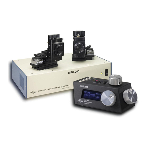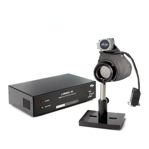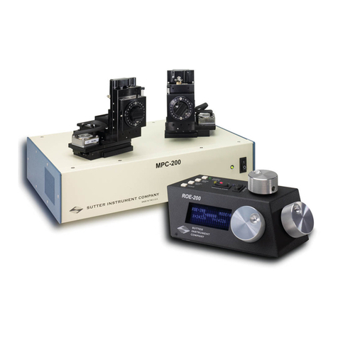
MPC-365 SERIES OPERATION MANUAL – REV. 3.21K (20201120)
TABLE OF CONTENTS
DISCLAIMER .......................................................................................................................................3
SAFETY WARNINGS AND PRECAUTIONS....................................................................................3
Electrical ..................................................................................................................................................3
Avoiding Electrical Shock and Fire-related Injury..............................................................................3
Electromagnetic Interference ................................................................................................................3
Operational ..............................................................................................................................................4
Other.........................................................................................................................................................5
Handling Micropipettes..........................................................................................................................5
1. INTRODUCTION...........................................................................................................................11
1.1 Structure of the MPC-365 Documentation Package ..................................................................11
1.2 Components of the MPC-365 Series .............................................................................................11
2. MPC-200 MULTI-MANIPULATOR CONTROLLER AND ROE-200 INPUT DEVICE
OPERATIONS ....................................................................................................................................13
2.1 Electrical Connections and Initial Operating Instructions........................................................13
2.2 Initial Operating Instructions .......................................................................................................13
2.3 Main Controls on the ROE-200.....................................................................................................15
2.3.1 White Buttons:..........................................................................................................................15
2.3.2 Black Selector Switches:..........................................................................................................16
2.3.3 Other Controls on the ROE-200.............................................................................................17
2.4 Controls on the MPC-200 ..............................................................................................................18
3. MP-865/M (AND MP-265/M) MANIPULATOR MECHANICAL MOUNTING
INSTRUCTIONS................................................................................................................................23
3.1 Mounting MP-865/M (or MP-265/M) to the MT-73 or MT-72 LS.............................................23
3.2 Setting Headstage/Pipette Angle and Pipette Exchange ...........................................................24
3.3 Headstage Mounting ......................................................................................................................24
3.4 Other Accessories............................................................................................................................26
3.5 Minimizing Electrical Noise ..........................................................................................................26
3.6 Instructions Used in Special Installations Only..........................................................................26
3.6.1 Instructions for Changing Handedness.................................................................................26
4. OPERATIONS ................................................................................................................................27
4.1 First Time Use ................................................................................................................................27
4.1.1 Line Power (Mains)..................................................................................................................27
4.2 Make It Go .......................................................................................................................................27
4.3 Basic Operation...............................................................................................................................28
4.3.1 Initialization .............................................................................................................................28
4.3.1 Standard Screen .......................................................................................................................28
4.3.2 No Manipulator Connected Screen ........................................................................................28
4.3.3 Diagonal-Mode Screen (DIAGONAL)....................................................................................28
4.3.4 Move in progress screen: .........................................................................................................29
4.3.5 Setting Work Position (WORK POS).....................................................................................29
5. EXTERNAL CONTROL ................................................................................................................31
5.1 General.............................................................................................................................................31
