IS 602 ECN 3913 Page 9 of 13
Thermostat
Remove facia and heat shield (C).
Unclip thermostat phial and remove thermostat, keeping the insulated sleeving to
reuse on the new thermostat.
Fit new thermostat, ensuring capillary is sleeved and routed to avoid internal
electrical shorting.
Refit facia.
Hotplate
Remove facia and heat shield (C) to access hotplate restraining nut.
Remove restraining nut and press the underside of the hotplate (D) up to facilitate
easy removal from above. Access to the hotplate connection block is now possible.
Fit new hotplate, ensuring wiring connections are correct.
Replacement is a reversal of the above.
Oven fans
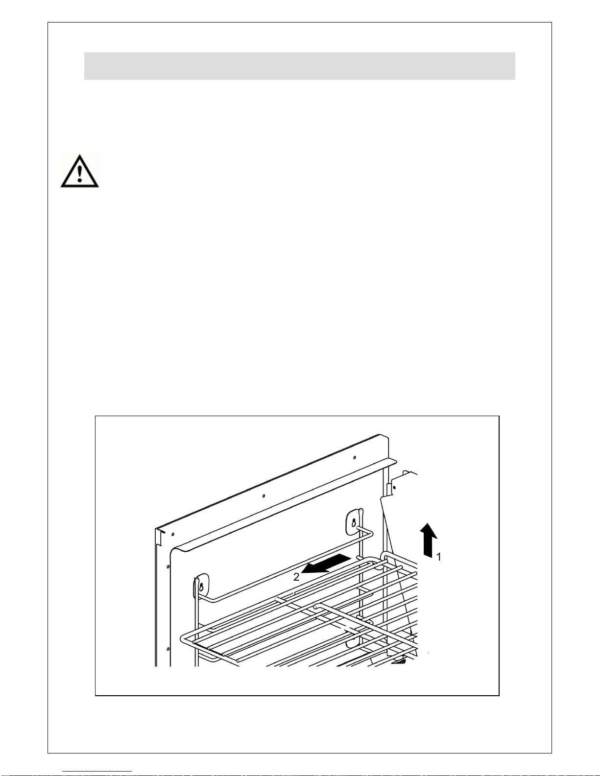
Remove the oven shelves (Fig 3).
Loosen the fan guard screws and lift off the keyhole slots.
Remove the hex head nut from the centre of the fan (LH thread). Remove the fan
blade.
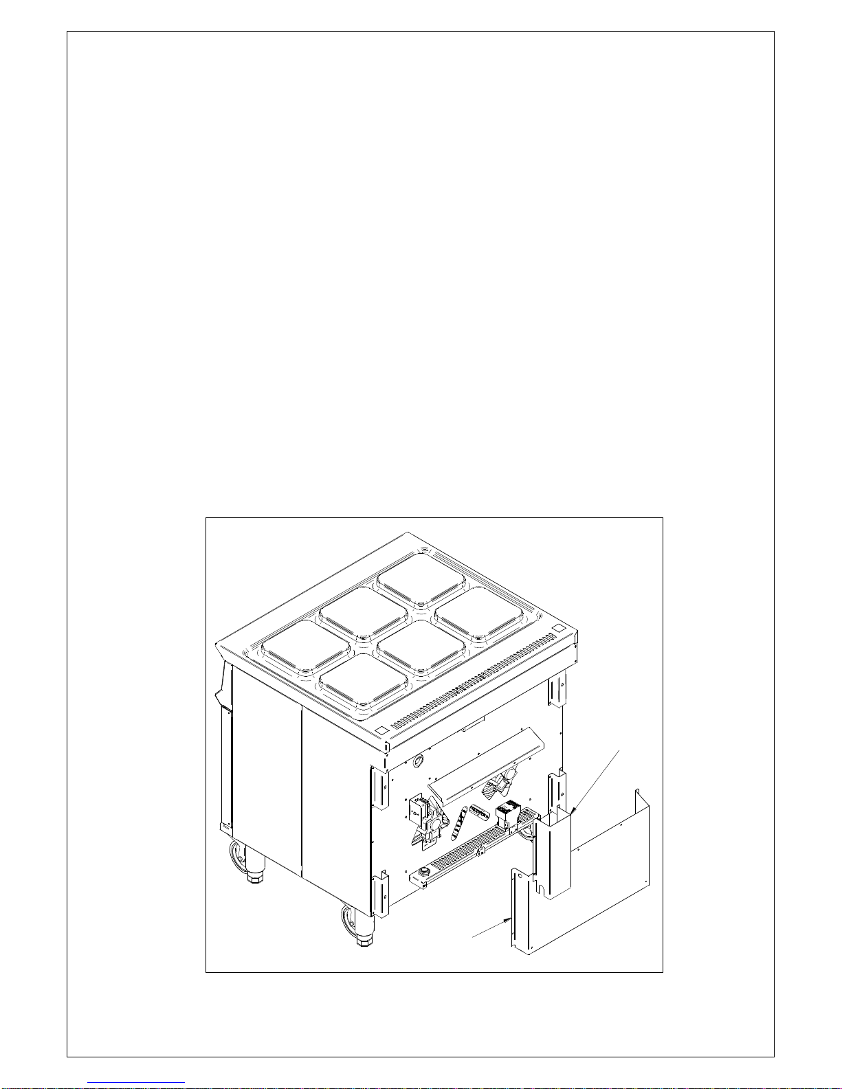
Working from the back of the appliance (Fig 5), remove the cable channel (E) and
rear cover (F).
Remove the electrical connections from the appropriate motor. Remove the 3
securing screws and extract the motor unit.
Reverse the procedure to fit new motor.
Contactor
Working from the back of the appliance (Fig 5), remove the cable channel (E) and
rear cover (F).
Remove the electrical connections from the contactor and connect to new
contactor.
Unclip old contactor, fit new contactor and rear cover.