Lincat LMO9 Manual

IS343 ECN3592
User, Installation and Servicing Instructions
Medium Duty Gas Freestanding Ovens
LMO9 and LMD9

IS343 ECN3592
2
Dear Customer,
Thank you for purchasing this Lincat product.
This is just one of over 450 different items of catering equipment available
which is constantly being extended and improved. Details are available from
your local distributor or direct from us.
Used for the purposes for which it is intended, and with careful maintenance
as outlined in this User Guide, your Lincat product will give you years of
trouble free service.
IMPORTANT INFORMATION
Please read all of the safety and operating instructions carefully before using
this product. Please pay particular attention to all sections of this User Guide
that carry warning symbols and notices.
WARNING!
This is a Warning symbol. This symbol is used throughout the user guide
whenever there is a risk of personal injury. Ensure that these warnings are read
and understood at all times.
CAUTION!
This is a Caution symbol. This symbol is used throughout the user guide
whenever there is a risk damaging your Lincat product. Ensure that these
warnings are read and understood at all times.
NOTE:
This is a Note symbol. This symbol is used throughout the user guide to provide
additional information, hints and tips.
NOTE

IS343 ECN3592
3
CONTENTS
Contents Page
Customer Information………………………………………………………. 2
Warnings and Precautions………………………………………………… 3
Technical Data……………………………………………………………….. 4
Commissioning………………………………………………………………. 5
Check List of Enclosures………………………………………………….. 5
Installation…………………………………………………….……………… 6
User…………………………………………………………………………….. 7
Servicing ……………………………………………………………………… 8
Component Replacement ………………………………………….……… 9
Spare Parts List……………………………………………………………… 10
Fault Finding…………………………………………………………………. 11
Service information………………………………………………………….. 12
Guarantee………………………………………………………….………….. 12
WARNINGS AND PRECAUTIONS
It is mandatory that all appliances are installed, commissioned and serviced by a
qualified and competent person as defined by the regulations in force in the country
of installation.
Failure to comply will invalidate the warranty.
WARNING!
This appliance must be installed by a competent installation engineer in accordance with
the installation instructions, and should conform to the following requirements:
Do not obstruct or block the appliance flue.
Installation must include sufficient ventilation to prevent the occurrence of unacceptable
concentrations of substances harmful to health in the room in which they are installed.
It is recommended that this appliance is sited under an extraction canopy for the removal of
combustion products
After operation, some parts of the appliance will remain hot for a period of time. Please take
care to avoid accidental burns.
CAUTION!
All equipment must be earthed to prevent shock.
Do not connect directly to any flue, ducting or mechanical extraction system.
Installation should allow for a sufficient flow of fresh air for gas combustion.
Parts which have been protected by the manufacturer or his agent must not be adjusted by
the installer or user.
This appliance is designated Category 1 and is therefore not intented for conversion from
one gas type to another.

IS343 ECN3592
4
TECHNICAL DATA
Model
LMO9
LMD9
Dimensions
Overall height (mm)
900
1650
Width (mm)
900
900
Depth (mm)
750
750
Weight (kg)
118kg
235kg
Usable oven capacity w x d x h (mm)
710 x 530 x 450
Oven shelf size (mm)
710 x 530
Heat Input
Total heat input Natural(Gross)
8.25 kW
16.5 kW
Total heat input Propane(Gross)
8.25 kW
16.5 kW
Total heat input Butane(Gross)
8.25 kW
16.5 kW
Connection and Operating Pressures
Gas inlet connection
½” BSPT Male (when nipple is fitted)
Supply Pressure - Natural
20mbar
Supply Pressure - Propane
37mbar
Supply Pressure - Butane
28-30mbar
NOTE: For those countries having a standard supply pressure of 50mbar for Butane or
Propane gas then the appliance is to be fitted with the regulator supplied for such country and
the operating pressure adjusted to the supply pressures above.
Gas Consumption
Total burner gas rate - Natural
0.79 m3h-1
1.57 m3h-1
Total burner gas rate - Propane
0.59 kg h-1
1.18 kg h-1
Total burner gas rate - Butane
0.60 kg h-1
1.20 kg h-1
Oven temperature range
130 –265 C

IS343 ECN3592
5
NOTE
COMMISSIONING
PREPARATION
Remove all packaging and protective coatings prior to installation.
Check that the burner caps have been fitted correctly to the burner body.
VENTILATION
The area in which this equipment is to be installed should have sufficient fixed ventilation to
comply with local legislation requirements. It is recommended that a room, or internal
space, be provided with a minimum free area of 4.5cm2per kW of total heat input.
CHECK LIST OF ENCLOSURES
Please ensure the following items are included with this piece of equipment:
Model
LMR9
LMD9
Tick
Warranty Card
1
1
Pressure Governor*
1
1
Connection Nipple (1/2" BSP)
1
1
User Instructions
1
1
*Supplied to countries having standard supply pressure of 50mbar for Butane or Propane gas.
SERIAL NUMBER
Each appliance manufactured at Lincat has a unique identifying number found in
the top right hand corner of the data plate attached at the rear of the appliance.
Please record that numer in the space provided should it be required for future
reference.
Serial Number
MARK OF CONFIDENCE
Every singe product that leaves our factory bears a serial plate showing the
assembler’s initials. It’s a mark of confidence we have in our people and our
manufacturing process.

IS343 ECN3592
6
INSTALLATION
SITING
The installer must ensure that all regulations are met and that there is an unobstructed
minimum distance of 1000mm from the top of the flue to the ceiling, which must be of non-
combustible material.
The appliance should be installed on a level surface ensuring the unit is stable and firmly
located.
Any partitions, walls or kitchen furniture in close proximity must be of non-combustible
materials and not be closer than 50mm from the sides and rear of the flue.
The LM9D has adjustable feet which must be set to level the appliance.
GAS SUPPLY AND CONNECTION
Connection is at the rear of the unit via a 1/2" G male thread.
Connection shall comply with local regulations, and the hose should be periodically
examined and replaced as necessary.
When making the connection to the appliance an isolating cock should be fitted into the
supply line close to the unit, for emergency shutdown or servicing purposes.
BURNER PRESSURE ADJUSTMENT
Applicable only to those countries having a standard supply pressure of 50mbar for Butane or Propane gas.
To gain access to the gas pressure test nipple open both oven doors (Lower if LMD9).
The nipple is situated beneath the control panel on the left of centre.
Remove the blanking screw and attach a pressure gauge to the boss of the test
nipple.
Light an oven burner with thermostat set to maximum.
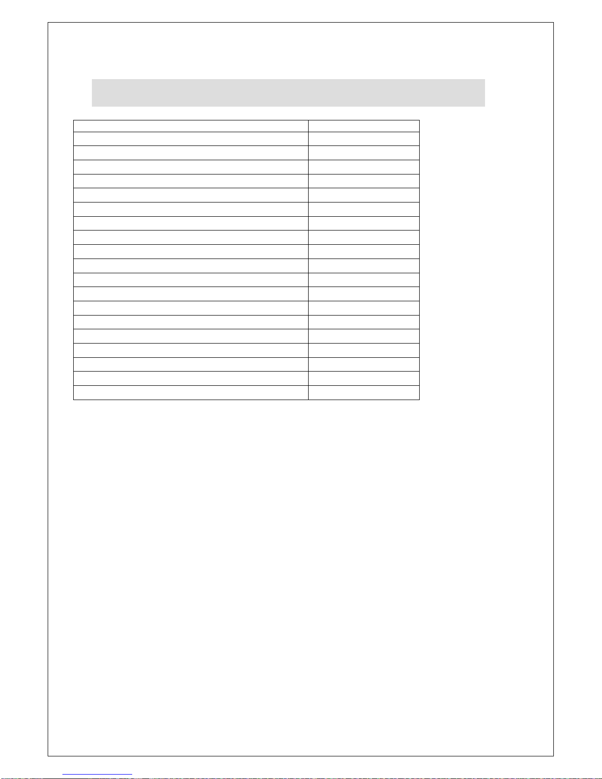
Adjust the pressure at the governor. See table above.
For appliances operating on Butane gas there may be some ‘yellowing’ of the flame at
the burner –this is nomal owning to the composition of the gas.
LOCKING OF WHEELS (LMO9 only)
When the appliance has been installed in its intended position the front casters should be
locked by depressing the locking tabs on the castors.
Locks should only be released for the intention of moving the appliance for
cleaning purposes and or routine servicing of the appliance.

IS343 ECN3592
7
USER INSTRUCTION
APPLIANCE USE
This appliance is only for professional use and should only be used by qualified personnel.
Ensure that the person responsible understands how to light, safely operate, clean and
shutdown the appliance and is made aware of the position and operation of the gas
isolating cock in the event of an emergency. All users should know how to clean burner
caps and to correctly locate the burner cap on the burner body.
LIGHTING SEQUENCE –OVEN BURNER
Open the main gas cock.
Open the right hand oven door.
Push in the control knob then rotate anti-clockwise to the spark position to allow gas
through to the burner. Depress the ignitor button on the control panel to light the gas
at the oven burner.
On establishing a flame at the burner, keep the knob depressed for approximately
15 seconds then release. The burner should remain lit. Rotate to desired
temperature setting.
SHUT DOWN
To shut down the appliance rotate all control knobs clockwise to the OFF position. The gas
supply stopcock or bottle valve should now be closed.
CLEANING
Ensure the appliance is cool and the gas supply is isolated before commencing
cleaning.
After use wash the unit down with a warm detergent solution.
Do not use abrasives on stainless steel or enamelled parts.
Do not use any products containing chlorine or hydrochloric acid to clean stainless
steel surfaces.
Do not clean the appliance using a water jet.
OVEN DOORS
Care must be taken when opening the oven doors whilst the appliance is in operation due
to the rapid escape of hot air.
HOT SURFACES
During normal running of the appliance some surfaces may become hot therefore care
must be taken whilst operating the appliance.

IS343 ECN3592
8
A
C
B
D
E
SERVICING
SERVICE ACCESS
To access and service the gas control valves
Remove the control knob/s A
and control panel C to gain
access to the valves.
Remove the two screws
securing the valve boss and
carefully withdraw the spindle
from the valve.
Grease as necessary and refit
parts. Carry out gas soundness
check.
Care should be taken when
removing the control panel
as the oven ignitor lead will
be attached to the ignitor B.
Carefully remove the lead
from the ignitor and temporarily tie to the manifold rail.
Note: Figure 1 shows LMO9 however, principle of
control panel removal is the same for the LMD9
To gain access from rear of appliance
Remove the two screws from the service
panel D.
Access to the thermostat capilliary and
thermostat bulb can now be obtained.
To remove the manifold rail the two
screws either side of the inlet port are to
be removed.
Note: Figure 2 shows LMO9 however, principle of service panel removal is the same for the LMD9
OPERATIONAL CHECK
Commissioning must include an operational check of all controls.
Check that each burner (where applicable) can be lit at any point on the thermostat
setting.
Check that each burner (where applicable) will remain lit when thermostat has cut to
low rate.
Figure 2
Figure 1

IS343 ECN3592
9
NOTE
COMPONENT REPLACEMENT
Oven Thermocouple
Remove the control knobs and fascia panel.
Remove nut from thermostat body.
Remove the thermocouple lock nuts W at the oven burner bracket.
Tape the new thermocouple to the old thermocouple. Withdraw the old
thermocouple whilst feeding through the new thermocouple.
Re-assemble in the reverse order.
Oven Thermostat
Remove the control knobs and fascia panel.
Remove the nuts and from the thermostat body.
Remove screw from the brackets, free the valve from the manifold rail.
Free the the thermostat bulb from the bracket within the oven cavity.
Remove the rear access panel and withdraw the thermostat bulb through the top of
the oven liner.
Fit the new thermostat and re-assemble reverse order.
Perform gas soundness test of circuit prior to operation of appliance.
Oven Burner injector
Remove the supply pipe nut Y and unscrew the parallel connector from the burner
body.
Remove the the injector holder
Remove the injector Z
Replace the copper and fibre washers and injector
Re-fit components
Perform gas soundness test of circuit prior to operation.
Oven Burner
Figure 3
X
W
Z
Y

IS343 ECN3592
10
Description
Part number
Door bush
BU55
Oven burner
BU78
Braked castor
CA112
Adjustable leg
LE42
Free running castor
CA113
Ingnitor electrode
IG16
Ignitor lead
IG18
Piezo ignitor
IG38
Thermostat bypass injector (Natural)
JE116
Thermostat bypass injector (Butane & Propane)
JE117
Oven injector (Natural)
JE64
Oven injector (Butane & Propane)
JE84
Thermostat control knob
KN154
Pressure Regulator
PG10
Shelf
SH75
Side rack
SR09
Oven thermocouple
TC33
Upper thermostat (complete) LMD9
TH16
Thermostat (complete) LMO9
TH17
SPARE PARTS LIST

IS343 ECN3592
11
Is there gas at the burner?Yes No
Are thermocouple connections loose?
Is the thermocouple voltage less than 3mV?
Is the valve damaged?
Check injector for blockages
Tighten connections
Replace valve
Yes
Yes
Yes
No
No
No
Replace thermocouple
Recheck system
Piezo oven ignitor not sparking.
Burner/s will not light or stay lit
FAULT FINDING
Check for a short in the high tension lead
Yes No
Replace lead
Replace electrode
Check electrode for fracture
Yes No
Replace piezo ignitor

IS343 ECN3592
12
Gas catering equipment should be routinely serviced to ensure a long trouble free life. It is
recommended that this appliances is serviced every 6 months by a competent gas
engineer.
For help regarding the installation, maintenance and use of your LINCAT equipment,
please call:-
LINCAT SERVICE HELP DESK
+44 (0) 1522 875520
AUTHORISED SERVICE AGENTS
We recommend that all servicing other than routine cleaning is carried out by our
authorised service agents. We cannot accept responsibility for work carried out by other
persons.
Please quote both the model and serial numbers from the data plate attached to the unit.
Give brief details of the service requirement.
If possible please quote the product code of the part number you require.
Work carried out under warranty will normally be undertaken only during normal working
hours, i.e. Monday to Friday, 8.30 a.m. - 5.00 p.m.
CONDITIONS OF GUARANTEE
The guarantee does not cover:-
1) Accidental breakage or damage
2) Operational misuse, wear and tear from normal usage, incorrect adjustment, or
neglect.
3) Incorrect installation, maintenance, modification or unauthorised service work.
SERVICE INFORMATION
This manual suits for next models
1
Table of contents
Other Lincat Oven manuals

Lincat
Lincat LYNX 400 LCO Service manual

Lincat
Lincat V6 Operating instructions

Lincat
Lincat CIBO User manual

Lincat
Lincat Silverlink 600 Owner's manual

Lincat
Lincat PO425 Operating instructions

Lincat
Lincat ECO8 User guide

Lincat
Lincat SLR6 User guide

Lincat
Lincat Silverlink 600 User guide

Lincat
Lincat Lynx 400 Owner's manual

Lincat
Lincat OE8008 Owner's manual
Popular Oven manuals by other brands

ARDESTO
ARDESTO EO-4415RCB instruction manual

TECNOEKA
TECNOEKA KF 966 AL UD Use and instruction manual

Equipex
Equipex PZ-400 Operation manual

Electrolux
Electrolux EOB 395 Instruction booklet

GE
GE JTP55BM Dimensions and installation information

Siemens
Siemens HM656GB 1 Series User manual and installation instructions