Lincoln Electric Bester Screen II User manual

AUTODARKENING
WELDING HELMET
Bester Screen II (p/n B3053-1-CE)
OPERATOR’S MANUAL
MANUALE OPERATIVO
BEDIENUNGSANLEITUNG
MANUAL DE INSTRUCCIONES
MANUEL D'UTILISATION
GEBRUIKSAANWIJZING
INSTRUKCJA OBSŁUGI
KÄYTTÖOHJE
MANUAL DE INSTRUÇÕES
ИНСТРУКЦИЯ ПО ЭКСПЛУАТАЦИИ
KASUTUSJUHEND
OPERATORIAUS VADOVAS
LIETOŠANAS ROKASGRĀMATA
NÁVOD K POUŽITÍ
NÁVOD NA POUŽÍVANIE
KEZELÉSI KÉZIKÖNYV
IM2082
01/2018
Rev 0
LINCOLN ELECTRIC EUROPE S.L
c/o Balmes, 89 - 802a, 08008 Barcelona, Spain
www.lincolnelectric.eu

AUTODARKENING
WELDING HELMET
Bester Screen II (p/n B3053-1-CE)
OPERATOR’S MANUAL
GRAPHICS MAY VARY
IM2082
01/2018
Rev 0
Declaration of conformity
Lincoln Electric Europe
Declares that the welding helmet B3053-1-CE conforms to the directive 89/686 EWG
and has been designed in compliance with standards EN 379, EN 166, EN 175
3rd January 2018
Pietro Terranova
Accessories Product Manager EMEAR
Lincoln Electric Europe S.L, c/o Balmes, 89 – 8° 2a, 08008 Barcelona, Spain
Notified bodies:
DIN CERTCO Gesellschaft fuer Konformitaetsbewertung mbH, Alboinstrasse 56, 12103 Berlin, Germany - Notified body number 0196 (Shield)
ADF model ADF615SLE marking explanation: CE 4/9-13 LE 1/1/1/2/379
4 : light state scale number
9 : lightest dark state scale number
13 : darkest state scale number
LE : filter manufacturer identification
1 : optical class
1 : diffusion of light class
1 : variations in luminous transmittance class
2 : angle dependence of luminous transmittance class
379 : number of the standard
Marking on shield, model TM9LE: "LE EN 175 B CE". LE : manufacturer's identification. EN 175: number of this standard. B: resistance to medium energy impact
Marking on front cover lens: "LE 1 B CE". LE : lens manufacturer's identification. 1: optical class. B: resistance to medium energy impact
Marking on Inside cover lens: "LE 1 B CE". LE : lens manufacturer's identification. 1: optical class. B: resistance to medium energy impact
LINCOLN ELECTRIC EUROPE S.L, c/o Balmes, 89 - 802a, 08008 Barcelona, Spain
www.lincolnelectric.eu
18
1

This equipment must be used by qualified personnel. Be sure that all installation, operation, maintenance and repair
procedures are performed only by qualified person. Read and understand this manual before operating this equipment.
Failure to follow the instructions in this manual could cause serious personal injury, loss of life, or damage to this equipment.
Read and understand the following explanations of the warning symbols. Lincoln Electric is not responsible for damages
caused by improper installation, improper care or abnormal operation. If protection against high speed particles at extremes
of temperature is required then the selected eye-protector should be marked with the letter “T” immediately after the
resistance to impact letter. If the impact letter is not followed by the letter “T” then the eye protector shall only be used against
high speed particles at room temperature. If the symbols F, B & A in the marking are not common to both the oculars and the
helmet then it is the lowest which shall be assigned to the complete eye protector.
WARNING: This symbol indicates that instructions must be followed to avoid serious personal injury, loss of life, or
damage to this equipment. Protect yourself and others from possible serious injury or death.
READ AND UNDERSTAND INSTRUCTIONS: Read and understand this manual before operating this equipment. Arc
welding can be hazardous. Failure to follow the instructions in this manual could cause serious personal injury, loss of life,
or damage to this equipment.
ELECTRIC SHOCK CAN KILL: Welding equipment generates high voltages. Do not touch the electrode, work clamp, or
connected work pieces when this equipment is on. Insulate yourself from the electrode, work clamp, and connected work
pieces.
ELECTRICALLY POWERED EQUIPMENT: Turn off input power using the disconnect switch at the fuse box before
working on this equipment. Ground this equipment in accordance with local electrical regulations.
ELECTRICALLY POWERED EQUIPMENT: Regularly inspect the input, electrode, and work clamp cables. If any
insulation damage exists replace the cable immediately. Do not place the electrode holder directly on the welding table or
any other surface in contact with the work clamp to avoid the risk of accidental arc ignition.
ELECTRIC AND MAGNETIC FIELDS MAY BE DANGEROUS: Electric current flowing through any conductor creates
electric and magnetic fields (EMF). EMF fields may interfere with some pacemakers, and welders having a pacemaker
shall consult their physician before operating this equipment.
CE COMPLIANCE: This equipment complies with the European Community Directives.
ARTIFICIAL OPTICAL RADIATION: According with the requirements in 2006/25/EC Directive and EN 12198 Standard,
the equipment is a category 2. It makes mandatory the adoption of Personal Protective Equipments (PPE) having filter
with a protection degree up to a maximum of 15, as required by EN169 Standard.
FUMES AND GASES CAN BE DANGEROUS: Welding may produce fumes and gases hazardous to health. Avoid
breathing these fumes and gases. To avoid these dangers the operator must use enough ventilation or exhaust to keep
fumes and gases away from the breathing zone.
ARC RAYS CAN BURN: Use a shield with the proper filter and cover plates to protect your eyes from sparks and the rays
of the arc when welding or observing. Use suitable clothing made from durable flame-resistant material to protect you skin
and that of your helpers. Protect other nearby personnel with suitable, non-flammable screening and warn them not to
watch the arc nor expose themselves to the arc.
WELDING SPARKS CAN CAUSE FIRE OR EXPLOSION: Remove fire hazards from the welding area and have a fire
extinguisher readily available. Welding sparks and hot materials from the welding process can easily go through small
cracks and openings to adjacent areas. Do not weld on any tanks, drums, containers, or material until the proper steps
have been taken to insure that no flammable or toxic vapors will be present. Never operate this equipment when
flammable gases, vapors or liquid combustibles are present.
WELDED MATERIALS CAN BURN: Welding generates a large amount of heat. Hot surfaces and materials in work area
can cause serious burns. Use gloves and pliers when touching or moving materials in the work area.
SAFETY MARK: This equipment is suitable for supplying power for welding operations carried out in an environment with
increased hazard of electric shock.
Materials which may come into contact with the wearer’s skin could cause allergic reactions to susceptible individuals.
This is not a safety helmet ! This helmet has been designed only to protect against the risks of welding processes.
2
WARNING

Do not dispose of electrical equipment together with normal waste!
In observance of European Directive 2012/19/EC on Waste Electrical and Electronic Equipment (WEEE) and its
implementation in accordance with national law, electrical equipment that has reached the end of its life must be collected
separately and returned to an environmentally compatible recycling facility. As the owner of the equipment, you should
get information on approved collection systems from our local representative.
By applying this European Directive you will protect the environment and human health!
Eye-protectors against high speed particles worn over standard ophthalmic spectacles may transmit impacts, thus
creating a hazard to the wearer
WEEE
HELMET INFORMATION
This Auto-Darkening Welding Helmet will automatically change from a light state (shade 3.5) to a dark state (Shade
9-13) when arc welding starts. The filter automatically returns to a light state when the arc stops. Shade control
adjustments can be made while welding. Match your welding application to the shade indicated on the shade chart.
(See Page 4). Do not use or open the auto-darkening filter if damaged by shock, vibration or pressure. The functionality
of the filter can be checked verifying its darkening when exposed to intense light (direct sun or welding flash). Keep
the sensors and solar cell clean. Clean the filter cartridge using a soapy water solution and soft cloth which should be
damp but not saturated. This Auto-Darkening Welding Helmet is designed for use with Stick Welding (SMAW); TIG
DC∾ TIG Pulse DC∾ MIG/MAG/CO2/Pulse; Plasma Arc Cutting (PAC); Plasma Arc Welding (PAW); Air Carbon
Arc Cutting (CAC-A); Grinding. The cartridge provides protection from harmful UV and IR radiation, in both dark and
light states. The cartridge contains two sensors to detect the light from the welding arc, resulting in the lens darkening
to a selected welding shade. Do not use solvents or abrasive cleaning detergent. . If cover lens is spattered or covered
with dirt, it should be replaced immediately. Do not use the helmet without inside and outside cover lenses properly
installed. We recommend a use of the helmet / ADF / safety oculars for a period of 3 years. The duration of use
depends on various factors such as use, cleaning storage and maintenance. Frequently inspections and replacement
if it is damaged are recommended.
CARTRIDGE OPERATIONS / FEATURES
Variable Shade Control
The shade can be adjusted from shade 9 to 13 based upon welding process or application (refer to Shade selection
chart). The variable shade control knob is mounted to shell for external adjustment.
Grind Mode
Used for metal grinding applications. In this mode, the shade function is turned off. The shade is fixed shade DIN 3.5
that allowing a clear view to grind a weld with the helmet providing face protection
LCD Viewing Area
Cartridge size
UV/IR Protection
Arc Sensors
Light State Shade
Variable Welding Shades
Shade Control
Grind mode
Power Supply
Power On/Off
Light to Dark Switching Time
TIG Rating
Operating Temperature
Storage Temperature
Total Weight
Compliance
3
96x40 mm (3.78x1.57 in)
110x90x9 mm (4.33x3.54x0.35 in)
Up to Shade DIN 16 at all times
2
DIN 3.5
DIN 9 to 13
External knob -full adjustment
Yes
Solar cells -no battery required
Fully automatic
1/16,000 sec
≥10 amps AC/DC
-5°C ~ 55°C (23°F ~ 131°F)
-20°C ~ 70°C (-4°F ~ 158°F)
430g (15.2 Oz.)
CE, EAC
SPECIFICATIONS HEADGEAR ADJUSTMENT
Crown
Adjustment
Ratchet
Knob
Headgear
Fore/Aft
Adjustment
Tilt
Adjustment

Sensitivity
The sensitivity can be set to “HI” (high) or “LO” (low) by using the infinitely dial knob on the back of the auto darkening
filter. The “Mid-High” setting is the normal setting for everyday use. The maximum sensitivity level is appropriate for low
welding current work, TIG, or special applications. Where the operation of the helmet is disturbed by excess ambient
light, or another welding machine close by, use the “LO” setting. As a simple rule for optimum performance, it is
recommended to set sensitivity to the maximum at the beginning and then gradually reduce it, until the filter reacts
onlyto the welding light flash and without annoying spurious triggering due to ambient light conditions (direct sun,
intensiveartificial light, neighbouring welder's arcs etc.).
Selecting delay time
When welding ceases, the viewing window automatically changes from dark back to light but with a pre-set delay to
compensate for any bright afterglow on the workpiece. The delay time / response can be set to “S” (short: 0.1 sec.)
or“L”(long: 1.0 sec.) as you require using the infinitely dial knob on the back of the auto darkening filter. It is
recommended to use a shorter delay with spot welding applications and a longer delay with applications using higher
currents. Longer delays can also be used for low current TIG welding, and TIG / MIG / MAG pulse.
ALWAYS TEST TO BE SURE THE ADF CARTRIDGE IS CHARGED BEFORE WELDING
The helmet can be placed in sunlight to charge. Do not store the helmet in a dark cabinet or other storage area for long
periods. While welding, the arc also charges the ADF cartridge.
Shade Selection Chart
Recommended shade numbers according to EN 379:2003
If your helmet does not include any one of the shades referenced above, it is recommended you use the next darker
shade.
HELMET MAINTENANCE AND CARE
Replacing Front Cover Lens : Replace the front cover lens
if it is damaged (cracked, soiled or pitted). Place your finger
or thumb into recess (C) at the bottom edge of the cover lens
and flex the lens upwards until it releases from the edges
marked A and B. (Refer to figure 1).
Replace the Inside Cover Lens: if it is damaged (cracked,
soiled or pitted). Place your fingernail in recess above
cartridge view window and flex lens upwards until it releases
from edges of cartridge view window.
Fitting New Cartridge: Take the new shade cartridge and
pass the potentiometer cable under the wire loop before
placing the cartridge into its retaining frame inside the helmet.
Hinge down the wire loop and ensure the front edge of the
loop (D) is properly retained under the retaining lugs (E) as
shown in figure 2.
Position the shade potentiometer to the inside of the helmet
with the shaft protruding through the hole.
Secure potentiometer to shell. On the outside of the helmet,
push the shade control knob onto the shaft.
Cleaning: Clean helmet by wiping with a soft cloth. Clean cartridge surfaces regularly. Do not use strong cleaning solutions.
Clean sensors and solar cells with soapy water solution and a clean cloth and wipe dry with a lint-free cloth. Do NOT
submerge shade cartridge in water or other solution.
Storage: Store in a clean, dry location.
4
PROCESS
MMAW (STICK ELECTRODES)
MAG
TIG
MIG
MIG WITH LIGHT ALLOYS
AIR-ARC COUGING
PLASMA JET CUTTING
MICROPLASMA ARC WELDING
2 6
8
8
8
8
10 15 30 40 60 70
CURRENT IN AMPERE
100 125 150 175 200 225 250 300 350 400 450 500 600
2 6 10 15 30 40 60 70 100 125 150 175 200 225 250 300 350 400 450 500 600
4 5 6 7
9
9
9
9
9
9
10 11
11
11
11
11
11
11
11
10
10
10
10
10
10
10
12
12
12
12
12
12
12
12
13
13
13
13
13
13
13
14
14
14
14
14
15
*** THIS HELMET IS NOT SUITABLE FOR LASER WELDING PROCESS ***
figure 1 figure 2

WARRANTY INFORMATION : These helmets are warranted for a period of one year.
Please contact your Lincoln Representative for any service or warranty questions.
SPATTER DAMAGE IS NOT COVERED BY WARRANTY : Do not use this product without the correct protective clear
cover lenses installed properly on both sides of the Auto-Darkening Filter cartridge (ADF). The cover lenses supplied
with this helmet are properly sized to work with this product and substitutions from other suppliers should be avoided.
WARRANTY INFORMATION
PART LIST
POS.
A
B
C
D
ITEM N.
KP3098-1
KP3053-1
KP3053-1-SB
KP3053-1-CE
DESCRIPTION
Front Cover Lens (2 pcs)
Inside Cover Lens (2 pcs)
Sweatband for helmet B3053-1-CE (2pcs)
Headgear Replacement Kit (includes headgear)
QTY
1
1
1
1
5
AB
C
D
LINCOLN ELECTRIC EUROPE S.L, c/o Balmes, 89 - 802a, 08008 Barcelona, Spain
www.lincolnelectric.eu

CASCO PER
SALDATURA AUTOSCURANTE
Bester Screen II (cod. B3053-1-CE)
LE GRAFICHE POSSONO VARIARE
IM2082
01/2018
Rev 0
Dichiarazione di conformità
Lincoln Electric Europe
Dichiara che il casco per saldatura B3053-1-CE è conforme alla direttiva 89/686 EWG
ed è stato progettato in conformità alle norme EN 379, EN 166, EN 175
3 gennaio 2018
Pietro Terranova
Accessories Product Manager EMEAR
Lincoln Electric Europe S.L, c/o Balmes, 89 – 8° 2a, 08008 Barcelona, Spain
Organismi notificati:
DIN CERTCO Gesellschaft fuer Konformitaetsbewertung mbH, Alboinstrasse 56, 12103 Berlin, Germany - Numero organismo notificato 0196 (Shield)
Spiegazione marcatura ADF, modelo ADF615SLE: CE 4/9-13 LE 1/1/1/2/379
4: Numero scala stato di trasparenza
9: Numero scala stato di oscuramento minimo
13: Numero scala stato di oscuramento massimo
LE : Identificazione produttore filtro
1: classe ottica
1: Classe di diffusione della luce
1: Classe di variazione della trasmittanza luminosa
2: Classe di dipendenza angolare della trasmittanza luminosa
379: Numero della normativa
Marcatura su maschera modello TM9LE: "LE EN 175 B CE". LE : Identificazione produttore. EN 175: Numero di questa normativa. B: Resistenza agli urti di media intensità
Marcatura su lente anteriore: "LE 1 B CE". LE : Identificazione produttore della lente. 1 : classe ottica. B: Resistenza agli urti di media intensità
Marcatura su lente interna: "LE S CE". LE : Identificazione produttore della lente. 1 : classe ottica. B: Resistenza agli urti di media intensità
LINCOLN ELECTRIC EUROPE S.L, c/o Balmes, 89 - 802a, 08008 Barcelona, Spain
www.lincolnelectric.eu
18
1
MANUALE D'USO E MANUTENZIONE

AVVERTENZA
Questa macchina deve essere impiegata solo da personale qualificato. Assicuratevi che tutte le procedure di installazione,
impiego, manutenzione e riparazione vengano eseguite solamente da persone qualificate. Leggere e comprendere questo
manuale prima di far funzionare la macchina. La mancata osservanza delle istruzioni di questo manuale può provocare seri
infortuni, anche mortali, alle persone o danni alla macchina. Leggere e comprendere le spiegazioni seguenti sui simboli di
avvertenza. La Lincoln Electric non si assume alcuna responsabilità per danni conseguenti a installazione non corretta,
incuria o impiego in modo anormale. Se si richiede la protezione dalla proiezione di particelle ad alta velocità a temperature
estreme, la protezione selezionata per gli occhi deve essere contrassegnata con la lettera “T” subito dopo la lettera che indica
la resistenza agli urti. Se dopo la lettera di protezione agli urti non è presente la lettera “T”, la protezione per gli occhi può
essere usata soltanto contro le particelle ad alta velocità a temperatura ambiente. Se i simboli F, B e A nelle marcature non
sono comuni sia per le lenti che per il casco, per la protezione completa per gli occhi si assegna il simbolo inferiore.
AVVERTENZA: Questo simbolo indica che occorre seguire le istruzioni per evitare seri infortuni, anche mortali, alle
persone o danni a questa macchina. Proteggete voi stessi e gli altri dalla possibilità di seri infortuni anche mortali.
LEGGERE E COMPRENDERE LE ISTRUZIONI: Leggere e comprendere questo manuale prima di far funzionare la
macchina. La saldatura ad arco può presentare dei rischi. La mancata osservanza delle istruzioni di questo manuale può
provocare seri infortuni, anche mortali, alle persone o danni alla macchina.
LA FOLGORAZIONE ELETTRICA E’ MORTALE: Le macchine per saldatura generano tensioni elevate. Non toccate
l’elettrodo, il morsetto di massa o pezzi da saldare collegati alla macchina quando la macchina è accesa. Mantenetevi
isolati elettricamente da elettrodo, morsetto e pezzi collegati a questo.
MACCHINA CON ALIMENTAZIONE ELETTRICA: Togliere l’alimentazione con l’interruttore ai fusibili prima di svolgere
operazioni su questa macchina. Mettere la macchina a terra secondo le normative vigenti.
MACCHINA CON ALIMENTAZIONE ELETTRICA: Ispezionare periodicamente i cavi di alimentazione, all’elettrodo e al pezzo.
Se si riscontrano danni all’isolamento sostituire immediatamente il cavo. Non posare la pinza portaelettrodo direttamente sul
banco di saldatura o qualsiasi altra superficie in contatto con il morsetto di massa per evitare un innesco involontario dell’arco.
I CAMPI ELETTRICI E MAGNETICI POSSONO ESSERE PERICOLOSI: Il passaggio di corrente elettrica in un conduttore
produce campi elettromagnetici. Questi campi possono interferire con alcuni cardiostimolatori (“pacemaker”) e i saldatori
con un cardiostimolatore devono consultare il loro medico su possibili rischi prima di impiegare questa macchina.
CONFORMITÀ CE: Questa macchina è conforme alle Direttive Europee.
RADIAZIONI OTTICHE ARTIFICIALI: Conformemente a quanto prescritto nella Direttiva 2006/25/CE ed alla Norma EN
12198, l'apparecchiatura è di categoria 2. Si rende obbligatoria l'adozione di Dispositivi di Protezione Individuale (DPI)
con grado di protezione del filtro fino ad un massimo di 15, secondo quanto prescritto dalla Norma EN169.
FUMI E GAS POSSONO ESSERE PERICOLOSI: La saldatura può produrre fumi e gas dannosi alla salute. Evitate di
respirare questi fumi e gas. Per evitare il pericolo l’operatore deve disporre di una ventilazione o di un'estrazione di fumi
e gas che li allontanino dalla zona in cui respira.
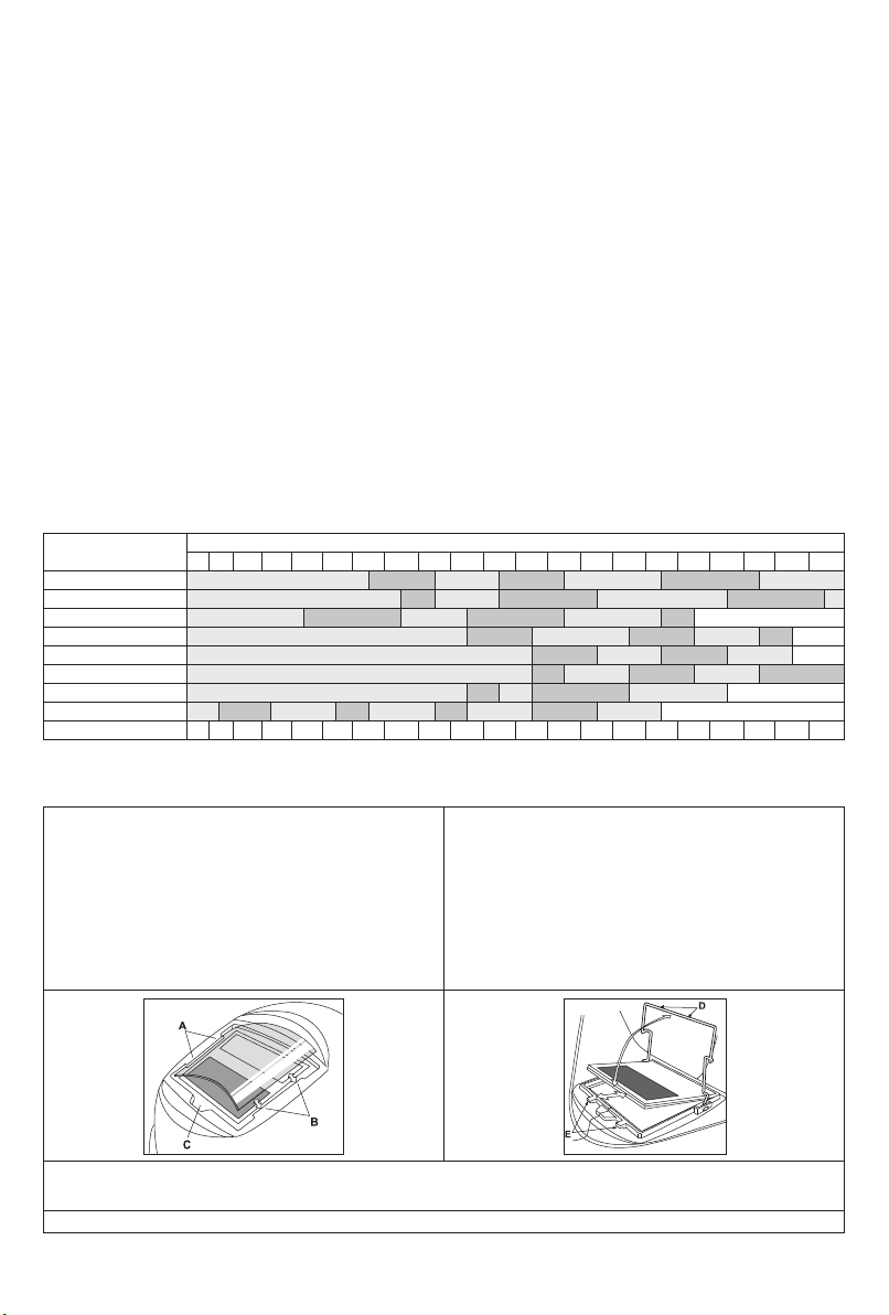
I RAGGI EMESSI DALL’ARCO BRUCIANO: Usate una maschera con schermatura adatta a proteggervi gli occhi da spruzzi
e raggi emessi dall’arco mentre saldate o osservate la saldatura. Indossare indumenti adatti in materiale resistente alla
fiamma per proteggere il corpo, sia vostro che dei vostri aiutanti. Le persone che si trovano nelle vicinanze devono essere
protette da schermature adatte, non infiammabili, e devono essere avvertite di non guardare l’arco e di non esporvisi.
GLI SPRUZZI DI SALDATURA POSSONO PROVOCARE INCENDI O ESPLOSIONI: Allontanare dall'area di saldatura quanto
può prendere fuoco e tenere a portata di mano un estintore. Gli spruzzi o altri materiali ad alta temperatura prodotti dalla
saldatura attraversano con facilità eventuali piccole aperture raggiungendo le zone vicine. Non saldare su serbatoi, bidoni,
contenitori o altri materiali fino a che non si sia fatto tutto il necessario per assicurarsi dell'assenza di vapori infiammabili o
nocivi. Non impiegare mai questa macchina se vi è presenza di gas e/o vapori infiammabili o combustibili liquidi.
I MATERIALI SALDATI BRUCIANO: Il processo di saldatura produce moltissimo calore. Ci si può bruciare in modo grave con le
superfici e materiali caldi della zona di saldatura. Impiegare guanti e pinze per toccare o muovere materiali nella zona di saldatura.
MARCHIO DI SICUREZZA: Questa macchina è adatta a fornire energia per operazioni di saldatura svolte in ambienti con
alto rischio di folgorazione elettrica.
L'eventuale contatto dei materiali con la pelle dell'operatore può causare reazioni allergiche a persone sensibili.
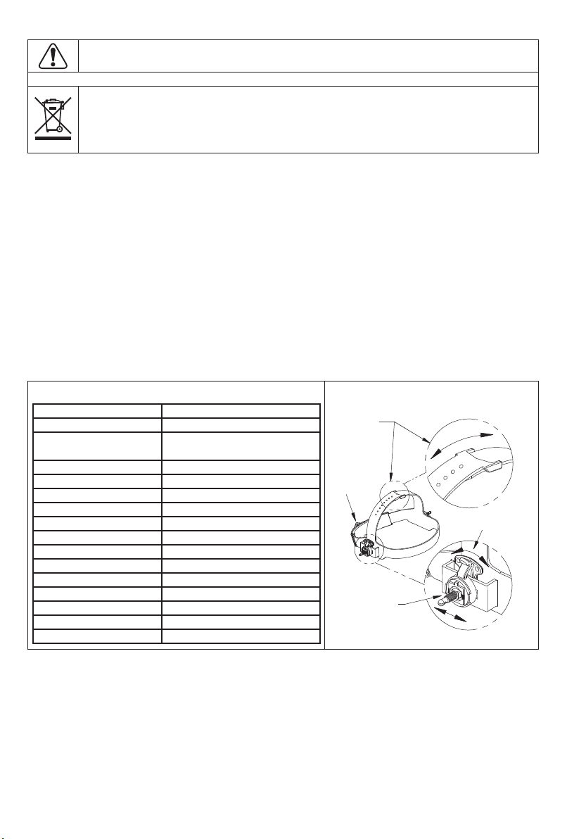
Questo non è un casco di sicurezza! Questo casco è stato progettato solo per la protezione dai rischi relativi ai processi
di saldatura.
2

Non smaltire le apparecchiature elettriche con i normali rifiuti!
In osservanza della Direttiva Europea 2012/19/Ce sui rifiuti di apparecchiature elettriche ed elettroniche (RAEE) e alla sua
implementazione in conformità alla normative locali, le apparecchiature elettriche giunte al termine della loro durata utile
devono essere raccolte separatamente e conferite ad un centro di riciclaggio ecocompatibile. In qualità di proprietario
dell'apparecchiatura, si dovrebbero ricevere informazioni sui sistemi di raccolta approvati dai nostri rappresentanti locali.
Applicando questa Direttiva europea si proteggono l'ambiente e vite umane!
WEEE/RAEE
INFORMAZIONI SUL CASCO
Questo casco per saldatura a oscuramento automatico passa automaticamente da uno stato di trasparenza (3.5) a uno
stato di oscuramento (9-13) quando si innesca l’arco di saldatura. Il filtro si riporta automaticamente ad uno stato di
trasparenza quando l'arco si arresta. Le regolazioni di controllo del grado di oscuramento possono avvenire durante la
saldatura. Adattare il grado di oscuramento all’applicazione di saldatura, in base alla tabella (vedere pagina 4). Non
usare o aprire il filtro auto-oscurante se danneggiato da urti, vibrazioni o pressione. La funzionalità del filtro può essere
controllata verificando il suo oscuramento quando esposto a luce intensa (sole diretto o flash di saldatura).Mantenere
puliti i sensori e le celle solari. Pulire la cartuccia del filtro con acqua saponata e un panno morbido umido (non
completamente imbevuto). Questo casco per saldatura a oscuramento automatico è progettato per i processi di
saldatura non portante (SMAW); TIG CC e CA; a impulsi TIG CC e CA; MIG/MAG/CO2/a impulsi; taglio ad arco-plasma
con arco diretto (PAC); saldatura ad arco-plasma (PAW); taglio ad arco con elettrodo di carbone ed aria compressa
(CAC-A); molatura. La cartuccia fornisce protezione contro le dannose radiazioni UV e IR, in entrambi gli stati di
oscuramento e trasparenza. La cartuccia contiene due sensori per rilevare la luce dell’arco di saldatura, provocando
l’oscuramento della lente a un grado prefissato. Non usare solventi o detergenti abrasivi. Se la lente di copertura è
macchiata o ricoperta di polvere, deve essere sostituita immediatamente. Non usare il casco senza lenti di copertura
interne ed esterne installate correttamente. Consigliamo l'uso di casco / ADF / lenti di sicurezza per un periodo
massimo di 3 anni. La durata d'uso dipende da vari fattori, quali impiego, pulizia, conservazione e manutenzione. Si
consiglia di ispezionarlo frequentemente e di sostituirlo, se danneggiato.
FUNZIONAMENTO/CARATTERISTICHE DELLA CARTUCCIA
Controllo di oscuramento variabile
L’oscuramento può essere regolato da gradazione 9 a 13 in funzione del processo di saldatura o dell’applicazione (fare
riferimento alla tabella per la selezione dell’oscuramento). La manopola di regolazione dell’oscuramento variabile è
montata sul guscio per la regolazione esterna.
Modalità molatura
Impiegata per applicazioni di molatura su metalli. In questa modalità, la funzione di oscuramento è disattivata.
L'oscuramento è quello fisso DIN 3.5 che consente la chiara visuale per la molatura di una saldatura con il casco che
assicura la protezione del viso 3
Area di visuale LCD
Dimensioni della cartuccia
Protezione UV/IR
Sensori d’arco
Stato di trasparenza
Grado di saldatura variabile
Controllo dell’oscuramento
Modalità molatura
Alimentatore
Interruttore ON/OFF
Tempo di commutazione
Corrente TIG
Temperatura di funzionamento
Temperatura di immagazzinamento
Peso totale
Conformità
96 x 40 mm (3.78x1.57 in)
110 x 90 x 9 mm (4.33x3.54x0.35 in)
Fino al grado di oscuramento
DIN 16 permanente
2
DIN 3.5
DIN da 9 a 13
Manopola esterna – regolazione completa
Sì
Celle solari – nessuna batteria necessaria
Completamente automatico
1/16.000 s
≥10 A CA/DC
Da -5°C a 55°C (da 23°F a 131°F)
Da -20°C a 70°C (da -4°F a 158°F)
430 g (15.2 Oz.)
CE, EAC
SPECIFICHE TECNICHE REGOLAZIONE DEL GIROTESTA
Regolazione
altezza girotesta
Manopola di
regolazione
sistema
Ratchet
Regolazione
longitudinale
girotesta
Regolazione
dell’inclinazione
protezioni per gli occhi contro le particelle ad alta velocità indossate sopra gli occhiali oftalmici standard possono
trasmettere impatti, creando così un pericolo per chi li indossa

Sensibilità
La sensibilità può essere impostata su “HI” (alta) o “LO” (bassa) mediante la manopola di regolazione continua sul retro
del filtro auto-oscurante. La regolazione “Mid-High” è quella normale per l'impiego di tutti i giorni. Il livello di sensibilità
massimo è adatto per lavori con bassa corrente di saldatura, TIG o applicazioni speciali. Ove il funzionamento del
casco sia disturbato dall'eccessiva luminosità ambientale o da un'altra saldatrice che operi nelle vicinanze, utilizzare la
regolazione “LO”. Come semplice regola per garantire prestazioni ottimali, si consiglia di impostare inizialmente la
sensibilità al livello massimo per poi ridurla gradualmente, fino a quando il filtro reagisce soltanto ai flash luminosi della
saldatura e senza fastidiose false attivazioni dovute alle condizioni della luminosità ambientale (raggi solari diretti,
intensa luce artificiale, archi di saldatrici che operino nelle vicinanze, ecc.).
Selezione del ritardo temporizzato
Al termine della saldatura, il visore passa automaticamente da scuro a chiaro, ma con un ritardo prestabilito per
compensare l'eventuale intenso bagliore residuo del pezzo. Il tempo di ritardo / risposta può essere opportunamente
impostato su “S” (breve: 0,1 s.) o “L”(lungo: 1,0 s) mediante la manopola di regolazione continua sul retro del filtro
auto-oscurante. Si consiglia di usare un ritardo più breve con applicazioni di saldatura a puntale e un ritardo più lungo
con applicazioni che impieghino correnti elevate. Ritardi più lunghi possono anche essere impiegati per la saldatura
TIG a bassa corrente e saldature TIG / MIG / MAG ad impulsi.
VERIFICARE SEMPRE CHE LA CARTUCCIA ADF SIA CARICA PRIMA DI INIZIARE A SALDARE
Il casco può essere esposto alla luce solare per la carica. Non conservare il casco in un armadietto o in altra zona buia
per lunghi periodi. Durante la saldatura, anche la luce dell’arco carica la cartuccia ADF.
Tabella per la selezione dell’oscuramento
Gradi di oscuramento raccomandati secondo la normativa EN 379:2003
Se il casco non prevede alcuno dei gradi di oscuramento riportati sopra, si raccomanda di usare il grado di
oscuramento maggiore immediatamente superiore.
MANUTENZIONE E CURA DEL CASCO
4
PROCESS
MMAW (STICK ELECTRODES)
MAG
TIG
MIG
MIG WITH LIGHT ALLOYS
AIR-ARC COUGING
PLASMA JET CUTTING
MICROPLASMA ARC WELDING
2 6
8
8
8
8
10 15 30 40 60 70
CURRENT IN AMPERE
100 125 150 175 200 225 250 300 350 400 450 500 600
2 6 10 15 30 40 60 70 100 125 150 175 200 225 250 300 350 400 450 500 600
4 5 6 7
9
9
9
9
9
9
10 11
11
11
11
11
11
11
11
10
10
10
10
10
10
10
12
12
12
12
12
12
12
12
13
13
13
13
13
13
13
14
14
14
14
14
15
*** QUESTO CASCO NON È ADATTO PER PROCESSI DI SALDATURA LASER ***
Sostituzione della lente di copertura anteriore: Sostituire
la lente anteriore se è danneggiata (incrinata, sporca o
butterata). Posizionare un dito nella fessura (C) sul bordo
inferiore della lente di copertura e flettere la lente verso l'alto
finché non fuoriesce dai bordi contrassegnati con A e B (fare
riferimento alla figura 1).
Sostituire la lente di copertura interna: Se danneggiata
(incrinata, sporca o butterata). Inserire un’unghia nella
fessura sopra la zona del visore della cartuccia e flettere la
lente verso l’alto fino a che non fuoriesce dai bordi della zona
del visore della cartuccia.
Montaggio nuova cartuccia: Estrarre la nuova cartuccia di
oscuramento e far passare il cavo del potenziometro sotto
l'ansa del filo prima di mettere la cartuccia nella sua struttura
di supporto all'interno del casco. Incardinare l'ansa del filo e
garantire che il bordo anteriore dell’ansa (D) sia
correttamente tenuto sotto gli agganci (E), come mostrato in
figura 2.
Posizionare il potenziometro di oscuramento all'interno del
casco con l'albero che sporge attraverso il foro.
Fissare il potenziometro al guscio. Sulla parte esterna del
casco, premere la manopola di controllo oscuramento
sull'albero.
Pulizia: Pulire il casco con un panno morbido. Pulire regolarmente le superfici della cartuccia. Non usare soluzioni detergenti
concentrate. Pulire i sensori e le celle solari con acqua saponata e un panno pulito e asciugare con un panno che non lasci
pelucchi. NON immergere la cartuccia oscurante in acqua o in altra soluzione.
Conservazione: Conservare in un luogo pulito e asciutto.
figura 1 figura 2

INFORMAZIONI SULLA GARANZIA: Questi caschi sono garantiti per un periodo di un anno.
Si prega di contattare il rappresentante Lincoln per tutte le domande di assistenza o di garanzia.
I DANNI DA SCHIZZI DI SALDATURA NON SONO COPERTI DA GARANZIA: Non usare questo prodotto senza le
lenti di copertura trasparenti protettive correttamente installate su entrambi i lati della cartuccia del filtro auto-oscurante
(ADF). Le lenti di copertura fornite con questo casco sono dimensionate specificatamente per lavorare con questo
prodotto e si sconsiglia la loro sostituzione con lenti di altri fornitori.
INFORMAZIONI DI GARANZIA
ELENCO PEZZI
POS.
A
B
C
D
N. ARTICOLO
KP3098-1
KP3053-1
KP3053-1-SB
KP3053-1-CE
DESCRIZIONE
Lente di copertura anteriore (2 pezzi)
Lente interna (2 pezzi)
Fascetta antisudore per casco B3053-1-CE (2 pezzi)
Kit sostituzione girotesta (completo di girotesta)
Q.TÀ
1
1
1
1
5
AB
C
D
LINCOLN ELECTRIC EUROPE S.L, c/o Balmes, 89 - 802a, 08008 Barcelona, Spain
www.lincolnelectric.eu

AUTOMATISCH ABDUNKELNDER
SCHWEISSERHELM
Bester Screen II (p/n B3053-1-CE)
BEDIENUNGSANLEITUNG
ABBILDUNGEN KÖNNEN ABWEICHEND AUSFALLEN
IM2082
01/2018
Rev. 0
Konformitätserklärung
Lincoln Electric Europe
Erklärt, dass der Schweißhelm B3053-1-CE der Richtlinie 89/686 EWG entspricht
und in Übereinstimmung mit den Normen EN 379, EN 166, EN 175 hergestellt wurde
3.Januar 2018
Pietro Terranova
Accessories Product Manager EMEAR
Lincoln Electric Europe S.L, c/o Balmes, 89 – 8° 2a, 08008 Barcelona, Spanien
Benannte Stellen:
DIN CERTCO Gesellschaft für KonformitätsbewertungmbH, Alboinstrasse 56, 12103 Berlin, Deutschland - Nummer der benannten Stelle 0196 (Schild)
Erläuterung ADF-Kennzeichnung, modell ADF615SLE: CE 4/9-13 LE 1/1/1/2/379
4 : Hellstufe
9 : Hellste Dunkelstufe
13 : Dunkelste Dunkelstufe
LE : Kennung des Filterherstellers
1 : Optische Klasse
1 : Streulichtklasse
1 : Homogenitätsklasse
2 : Winkeleigenschaften
379 : Nummer der Norm
Markierung an Schild: "LE EN 175 B CE". LE : Herstellerkennzeichnung. EN 175: Nummer dieser Norm. B: Widerstand zu mittlerer Aufprallenergie
Markierung an vorderer Abdeckscheibe: "LE 1 B CE". LE : Kennzeichnung des Glasherstellers. 1 : Optische Klasse. B: Widerstand zu mittlerer Aufprallenergie
Markierung an innerer Abdeckscheibe: "LE 1 B CE". LE : Kennzeichnung des Glasherstellers. 1 : Optische Klasse.
LINCOLN ELECTRIC EUROPE S.L, c/o Balmes, 89 - 802a, 08008 Barcelona, Spanien
www.lincolnelectric.eu
18
1

ACHTUNG: Dieses Symbol gibt an, dass die folgenden Hinweise beachtet werden müssen, um gefährliche Verletzungen bis hin zum
Tode oder Beschädigungen am Gerät zu verhindern. Schützen Sie sich und andere vor gefährlichen Verletzungen oder dem Tode.
BEACHTEN SIE DIE ANLEITUNG: Sie dürfen dieses Gerät erst betreiben, wenn Sie diese Betriebsanleitung gelesen und
verstanden haben. Lichtbogenschweißen kann gefährlich sein. Bei Nichtbeachtung der Hinweise kann es zu
gefährlichen Verletzungen bis hin zum Tod oder zu Beschädigungen am Gerät kommen.
STROMSCHLÄGE KÖNNEN TÖDLICH SEIN: Schweißgeräte erzeugen hohe Stromstärken. Berühren Sie die
Elektrode, Masseklemme oder angeschlossene Werkstücke nicht, wenn die Anlage eingeschaltet ist. Schützen Sie sich
selbst vor der Elektrode, der Masseklemme und angeschlossenen Werkstücken.
ELEKTRISCHE GERÄTE: Schalten Sie die Netzspannung am Sicherungskasten aus, bevor Arbeiten an der Maschine
ausgeführt werden. Erden Sie die Maschine gemäß den örtlich geltenden elektrischen Bestimmungen.
ELEKTRISCHE GERÄTE: Überprüfen Sie regelmäßig Netz-, Werkstück- und Elektrodenkabel. Tauschen Sie diese bei
Beschädigung sofort aus. Legen Sie den Elektrodenhalter niemals auf den Schweißarbeitsplatz, damit es zu keinem
ungewollten Lichtbogen kommt.
ELEKTRISCHE UND MAGNETISCHE FELDER BERGEN GEFAHREN: Elektrischer Strom, der durch ein Kabel fließt,
erzeugt ein elektrisches und magnetisches Feld (EMF). EMF können Herzschrittmacher beeinflussen. Bitte fragen Sie
Ihren Arzt, wenn Sie einen Herzschrittmacher haben, bevor Sie dieses Gerät benutzen.
EG KONFORMITÄT: Dieses Gerät erfüllt die EU-Richtlinien.
OPTISCHE STRAHLUNG AUS KÜNSTLICHEN QUELLEN: Gemäß den Anforderungen der EU-Richtlinie 2006/25/EG
und der Norm EN 12198 wird dieses Produkt in Kategorie 2 eingestuft. Das Tragen persönlicher Schutzausrüstungen
(PSA) mit Schutzgläsern bis Stufe 15 ist nach EN169 zwingend vorgeschrieben.
RAUCH UND GASE KÖNNEN GEFÄHRLICH SEIN: Schweißen erzeugt Rauch und Gase, die gesundheitsschädlich sein
können. Vermeiden Sie das Einatmen dieser Metalldämpfe. Benutzen Sie eine Schweißrauchabsaugung, um die
Dämpfe abzusaugen.
LICHTBÖGEN KÖNNEN VERBRENNUNGEN HERVORRUFEN: Benutzen Sie einen Schild mit dem richtigen Filter und Schutzmasken
zum Schutz der Augen vor Spritzern und Strahlungen beim Schweißen oder Beobachten. Tragen Sie angemessene Kleidung aus nicht
brennbarem Material zum Schutz Ihrer Haut und der Ihrer Helfer. Schützen Sie auch in der Umgebung befindliche Personen mit
angemessenen, nicht brennbaren Schilden und lassen Sie niemanden ungeschützt den Lichtbogen beobachten oder sich ihm aussetzen.
SCHWEISSSPRITZER KÖNNEN FEUER ODER EXPLOSIONEN VERURSACHEN: Entfernen Sie feuergefährliche Gegenstände
vom Schweißplatz und halten Sie einen Feuerlöscher bereit. Beim Schweißen entstehende Funken und heiße Materialteile können
sehr leicht durch kleine Ritzen und Öffnungen in umliegende Bereiche gelangen. Schweißen Sie keine Tanks, Trommeln, Behälter
oder andere Gegenstände, bis die erforderlichen Maßnahmen durchgeführt wurden, damit keine entflammbaren oder giftigen Dämpfe
mehr vorhanden sind. Bedienen Sie diese Ausrüstung nicht, wenn brennbare Gase, Dämpfe oder Flüssigkeiten vorhanden sind.
GESCHWEISSTE MATERIALIEN KÖNNEN VERBRENNUNGEN VERURSACHEN: Schweißen verursacht hohe
Temperaturen. Heiße Oberflächen und Materialien im Arbeitsbereich können ernsthafte Verbrennungen verursachen.
Benutzen Sie Handschuhe und Zangen, wenn Sie geschweißte Materialien berühren oder bewegen.
S-ZEICHEN: Dieses Gerät darf Schweißstrom in Umgebungen mit erhöhter elektrischer Gefährdung liefern.
Materialien, die mit der Haut des Trägers in Kontakt kommen können, könnten bei empfindlichen Personen allergische
Reaktionen hervorrufen.
Dies ist kein Sicherheitshelm! Dieser Helm wurde ausschließlich zum Schutz vor den Risiken von Schweißprozessen entwickelt.
2
WARNUNG
Diese Anlage darf nur von geschultem Fachpersonal genutzt werden. Installation, Bedienung, Wartung und Reparaturen
dürfen nur von qualifiziertem Personal durchgeführt werden. Sie dürfen dieses Gerät erst betreiben, wenn Sie diese
Betriebsanleitung gelesen und verstanden haben. Bei Nichtbeachtung der Hinweise kann es zu gefährlichen Verletzungen bis
hin zum Tod oder zu Beschädigungen am Gerät kommen. Beachten Sie auch die folgenden Beschreibungen der
Warnhinweise. Lincoln Electric ist nicht verantwortlich für Fehler, die durch inkorrekte Installation, mangelnde Sorgfalt oder
Fehlbenutzung des Gerätes entstehen. Wenn der Schutz gegen Hochgeschwindigkeitspartikel bei extrem hohen
Temperaturen erforderlich ist, dann sollte der gewählte Augenschutz mit dem Festigkeitssymbol gefolgt vom Buchstaben “T”
markiert sein. Wenn dem Festigkeitssymbol nicht der Buchstabe “T” folgt, dann sollte der Augenschutz nur zum Schutz von
Hochgeschwindigkeitspartikel bei Raumtemperatur verwendet werden. Wenn die Symbole F, B & A in der Markierung nicht
gleich auf Okularen und Helm sind, muss das niedrigste für den vollständigen Augenschutz zugewiesen werden.

Werfen Sie Elektrowerkzeuge nicht in den Hausmüll!
Unter Beachtung der Europäischen Richtlinie 2012/19/EU über Elektro- und Elektronik-Altgeräte (Waste Electrical and
Electronic Equipment - WEEE) und ihrer Durchführung gemäß nationaler Gesetzgebung, müssen elektrische Geräte, die
das Ende ihrer Lebensdauer erreicht haben, getrennt gesammelt und bei einer entsprechenden Entsorgungseinrichtung
abgegeben werden. Als Eigentümer dieses Gerätes sollten Sie sich Informationen über ein örtliches autorisiertes
Sammel- bzw. Entsorgungssystem einholen.
Mit der Anwendung dieser EU-Richtlinie tragen Sie wesentlich zur Schonung der Umwelt und ihrer Gesundheit bei!
WEEE
INFORMATIONEN ZU DEM HELM
Dieser selbstverdunkelnde Schweißhelm wechselt bei Schweißbeginn automatisch vom Hellzustand (DIN-Schutzstufe
3.5) in den Dunkelzustand (DIN-Schutzstufen 9-13). Wenn der Lichtbogen erlischt, nimmt der Schutzfilter wieder den
Hellzustand an. Die eingestellte Schutzstufe kann während des Schweißens geändert werden. Stellen Sie Ihre
Schweißanwendung auf die in dem Schutzstufendiagramm angegebene Schutzstufe ein. (Siehe Seite 4). Benutzen
oder öffnen Sie den Schutzfilter nicht, wenn er durch Schläge, Vibration oder Druck beschädigt wurde. Die
Funktionsfähigkeit des Filters kann überprüft werden, indem bei intensivem Licht (direkte Sonneneinstrahlung oder
Schweißblitz) seine Verdunkelung festgestellt wird. Sensoren und Solarzellen sauber halten. Reinigen Sie die
Filterkartusche mit Seifenwasser und einem weichen Tuch, das feucht, aber nicht zu nass sein sollte. Dieser
selbstverdunkelnde Schweißhelm ist für die Verwendung mit Stabschweißen (SMAW) entwickelt; WIG DC∾ WIG
Pulse DC∾ MIG/MAG/CO2/Pulse; Plasma Lichtbogenschneiden (PAC); Plasma Lichtbogenschweißen (PAW); Luft
-Kohle Lichtbogenschneiden (CAC-A); Schleifen. Die Kartusche bietet Schutz vor schädlichen UV- und IR-Strahlen,
sowohl im dunklen wie auch im hellen Zustand. Die Kartusche enthält zwei Sensoren, die das Licht des
Schweißlichtbogens entdecken. Das führt zum Verdunkeln der Scheibe bis in die gewählte Schutzstufe. Für die
Reinigung keine Lösungsmittel oder Schleifmittel verwenden. Eine mit Spritzern oder Dreck bedeckte Abdeckscheibe
ist unverzüglich auszutauschen. Verwenden Sie den Helm nicht ohne sachgemäß angebrachte innere und äußere
Abdeckscheibe. Wir empfehlen eine Verwendung von Helm / ADF / Sicherheitsokulare für einen Zeitraum von 3
Jahren. Die Dauer der Verwendung hängt von verschiedenen Faktoren ab, wie Gebrauch, Reinigung, Lagerung und
Pflege. Regelmäßige Kontrollen und Austausch bei Beschädigung werden empfohlen.
BEDIENUNG / FUNKTIONEN DER FILTERKASSETTE
Variable Schutzstufensteuerung
Die Abdunkelung kann je nach Schweißverfahren oder Anwendung auf eine der Schutzstufen 9 bis 13 eingestellt
werden (vgl. Tabelle zur Schutzstufenauswahl). Der Regulierknopf für die Schutzstufe ist an der Helmschale
angebracht, damit er von außen bedient werden kann.
Schleifmodus
Verwendet für Metallschleifanwendungen. In diesem Modus ist die Abdunkelungsfunktion ausgeschaltet. Der Schutz
ist ein fester Schutz DIN 3.5, der eine klare Sicht ermöglicht, um eine Schweißnaht zu schleifen, wobei der Helm
Gesichtsschutz bietet
LCD Sichtfeld
Kartuschengröße
UV/IR Schutz
Lichtbogensensoren
Hellzustand-Schutzstufe
Variable Schweißschutzstufen
Steuerung der Schutzstufe
Schleifmodus
Stromversorgung
Ein/Aus
Schaltzeit von hell nach dunkel
WIG bemessen
Betriebstemperatur
Lagerungstemperatur
Gesamtgewicht
Konformität
3
96x40 mm (3.78x1.57 in)
110x90x9 mm (4.33x3.54x0.35 in)
Konstante Abdunkelung DIN 16
2
DIN 3,5
DIN 9 bis 13
Knopf außen - volle Einstellung
Ja
Solarzellen - keine Batterie nötig
Vollautomatik
1/16,000 Sek
≥10 amps AC/DC
-5°C ~ 55°C (23°F ~ 131°F)
-20°C ~ 70°C (-4°F ~ 158°F)
430g (15.2 Oz.)
CE, EAC
TECHNISCHE DATEN ANPASSEN DES KOPFBANDS
Wölbungs-
einstellung
Einrastender
Drehknopf
Einstellen
des Kopfbands
vorne/hinten
Neigungs-
einstellung
Augenschützer gegen Hochgeschwindigkeitsteilchen, die über Standard-Augenbrillen getragen werden, können Schläge
übertragen und somit eine Gefahr für den Träger darstellen

Empfindlichkeit
Die Empfindlichkeit kann mit dem stufenlos einstellbaren Drehknopf auf der Rückseite des automatischen Schutzfilters
auf “HI” (hoch) oder “LO” (niedrig) eingestellt werden. Die Einstellung “Mid-High” ist die normale Einstellung für den
täglichen Gebrauch. Die maximale Empfindlichkeitsstufe eignet sich für Arbeiten mit geringem Schweißstrom, WIG
oder Spezialanwendungen. Wenn die Funktion des Helms durch zu starkes Umgebungslicht oder ein anderes
Schweißgerät in der Nähe gestört wird, die Einstellung “LO” verwenden. Als einfache Regel für eine optimale Leistung
empfiehlt es sich, die Empfindlichkeit zu Beginn auf das Maximum einzustellen und dann allmählich zu reduzieren, bis
der Filter nur auf den Schweißlichtblitz reagiert und ohne störende Fehlauslösung aufgrund von
Umgebungslichtbedingungen (direkte Sonneneinstrahlung, intensives Kunstlicht, benachbarte Schweißerbögen usw.).
Auswahl der Verzögerungszeit
Wenn das Schweißen aufhört, wechselt das Sichtfenster automatisch von dunkel auf hell, jedoch mit einer
voreingestellten Verzögerung, um ein helles Nachleuchten des Werkstücks auszugleichen. Die Verzögerungszeit /
Rückmeldung kann mit dem stufenlos einstellbaren Drehknopf auf der Rückseite des automatischen Schutzfilters auf
“S” (kurz: 0.1 Sek.) oder“L”(lang: 1.0 Sek.) je nach Bedarf eingestellt werden. Es wird empfohlen, bei
Punktschweißanwendungen eine kürzere Verzögerung und bei Anwendungen mit höheren Strömen eine längere
Verzögerung zu verwenden. Längere Verzögerungen können auch für das WIG-Schweißen mit geringem Strom und
WIG / MIG / MAG-Impuls verwendet werden.
VOR DEM SCHWEISSEN IMMER PRÜFEN, OB DIE ADF-KASSETTE GELADEN IST
Zum Aufladen brauchen Sie den Helm nur dem Sonnenlicht aussetzen. Lagern Sie den Helm nicht längere Zeit in
dunklen Kammern oder anderen dunklen Lagerbereichen. Während des Schweißens wird die ADF-Kassette auch
durch den Lichtbogen aufgeladen.
Tabelle zur Schutzstufenauswahl
Empfohlene Schutzstufen nach EN 379:2003
Wenn Ihr Helm keine der oben aufgeführten Schutzstufen aufweist, sollten Sie die nächstdunklere Stufe nehmen.
HELM - PFLEGE UND INSTANDHALTUNG
4
PROCESS
MMAW (STICK ELECTRODES)
MAG
TIG
MIG
MIG WITH LIGHT ALLOYS
AIR-ARC COUGING
PLASMA JET CUTTING
MICROPLASMA ARC WELDING
2 6
8
8
8
8
10 15 30 40 60 70
CURRENT IN AMPERE
100 125 150 175 200 225 250 300 350 400 450 500 600
2 6 10 15 30 40 60 70 100 125 150 175 200 225 250 300 350 400 450 500 600
4 5 6 7
9
9
9
9
9
9
10 11
11
11
11
11
11
11
11
10
10
10
10
10
10
10
12
12
12
12
12
12
12
12
13
13
13
13
13
13
13
14
14
14
14
14
15
*** DIESER HELM IST NICHT FÜR LASERSCHWEISSPROZESSE GEEIGNET ***
Austausch der vorderen Abdeckscheibe: Tauschen Sie
die vordere Abdeckscheibe aus, wenn sie beschädigt
(gerissen, verdreckt oder verkratzt) ist. Drücken Sie mit dem
Finger oder Daumen in die Mulde (C) am unteren Rand der
Abdeckscheibe und biegen Sie diese nach oben, bis sie an
den mit A und B gekennzeichneten Kanten freigegeben wird.
(Vgl. Abb. 1).
Tauschen Sie die innere Abdeckscheibe aus: wenn sie
beschädigt (gerissen, verdreckt oder verkratzt) ist. Stecken
Sie Ihren Fingernagel in die Mulde über dem Sichtfenster der
Kassette und biegen Sie die Scheibe nach oben, bis sie sich
aus den Kanten des Sichtfensters der Kassette lost.
Einsetzen der neuen Filterkassette: Nehmen Sie die neue
Filterkassette und führen Sie das Drehreglerkabel unter dem
Drahtbügel hindurch, bevor Sie die Kassette in ihren
Aufnahmerahmen im Helm einsetzen. Klappen Sie den
Drahtbügel herunter und achten Sie darauf, dass die
Vorderkante des Drahtbügels (D) korrekt unter den Laschen
(E) festgehalten wird, wie in Abb. 2 dargestellt.
Setzen Sie den Abdunkelungsdrehregler so an der
Helminnenseite ein, dass die Reglerwelle aus dem Loch
herausragt.
Befestigen Sie den Drehregler an der Helmschale. Schieben
Sie den Regulierknopf für die Schutzstufe außen am Helm
auf die Reglerwelle.
Reinigung: Reinigen Sie den Helm durch Abwischen mit einem weichen Tuch. Reinigen Sie die Oberflächen der
Filterkassette regelmäßig. Verwenden Sie keine scharfen Reinigungslösungen. Reinigen Sie Sensoren und Solarzellen mit
Seifenwasser und einem sauberen Tuch und wischen Sie sie mit einem fusselfreien Tuch trocken. Tauchen Sie die Kassette
NICHT in Wasser oder andere Lösungen.
Lagerung: An einem sauberen, trockenen Platz lagern.
Abb. 1 Abb. 2

GARANTIEBESTIMMUNGEN: Die Garantiefrist für diese Helme beträgt ein Jahr.
Bei Fragen zu Service oder Garantie wenden Sie sich bitte an Ihre Lincoln-Vertretung.
DIE GARANTIE UMFASST KEINE SCHÄDEN DURCH SCHWEISSSPRITZER: Verwenden Sie dieses Produkt nur,
wenn die richtigen Abdeckscheiben korrekt an beiden Seiten der selbstverdunkelnden Filterkassette (ADF) angebracht
sind. Die mit diesem Helm gelieferten Abdeckscheiben passen in der Größe genau zu diesem Produkt. Austauschteile
von anderen Lieferanten sollten nicht verwendet werden.
GARANTIEBESTIMMUNGEN
ERSATZTEILLISTE
POS.
A
B
C
D
SACH-NR.
KP3098-1
KP3053-1
KP3053-1-SB
KP3053-1-CE
BESCHREIBUNG
Vordere Abdeckscheibe (2 Stück)
Innere Abdeckscheibe (2 Stück)
Schweißband für Helm B3053-1-CE (2 Stück)
Kopfband Austauschsatz (einschließlich Kopfband)
ANZ.
1
1
1
1
5
AB
C
D
LINCOLN ELECTRIC EUROPE S.L, c/o Balmes, 89 - 802a, 08008 Barcelona, Spanien
www.lincolnelectric.eu

PANTALLA DE SOLDADURA
AUTO-OSCURECIBLE
Pantalla Bester II (p/n B3053-1-CE)
MANUAL DE INSTRUCCIONES
EL PRODUCTO PUEDE NO SER EXACTAMENTE IGUAL A LA IMAGEN
IM2082
01/2018
Rev. 0
Declaración de conformidad
Lincoln Electric Europe
Declara que la pantalla de soldadura B3053-1-CE cumple la directiva 89/686 EWG
y ha sido diseñada de acuerdo con las normas EN 379, EN 166, EN 175
3 de enero de 2018
Pietro Terranova
Gerente de productos accesorios de EMEAR
Lincoln Electric Europe S.L, c/o Balmes, 89 – 8° 2a, 08008 Barcelona, Spain
Organismos notificados:
DIN CERTCO Gesellschaft fuer Konformitaetsbewertung mbH, Alboinstrasse 56, 12103 Berlin, Germany - Notified body number 0196 (Shield)
Explicación de los números del filtro auto-oscurecible (ADF), modelo ADF615SLE: CE 4/9-13 LE 1/1/1/2/379
4: N.º de matiz de claridad máxima
9: N.º de matiz de oscuridad mínima
13: N.º de matiz de oscuridad máxima
LE : identificación del fabricante del filtro
1: clase óptica
1: clase en función de la difusión de la luz
1: clase en función de las variaciones de la transmitancia luminosa
2: clase en función de la dependencia del ángulo de la transmitancia luminosa
379: número de la norma
Marca en la pantalla: "LE EN 175 B CE". LE : identificación del fabricante. EN 175: número de la norma. B: resistencia a impactos de fuerza media
Marcado en la lente de protección delantera: "LE 1 B CE". LE : identificación del fabricante de la lente. 1 : clase óptica. B: resistencia a impactos de fuerza media.
Marcado en la lente de protección interior: "LE 1 B CE". LE : identificación del fabricante de la lente. 1 : clase óptica. B: resistencia a impactos de fuerza media
LINCOLN ELECTRIC EUROPE S.L, c/o Balmes, 89 - 802a, 08008 Barcelona, Spain
www.lincolnelectric.eu
18
1

ADVERTENCIA: este símbolo indica qué instrucciones se deben seguir para evitar lesiones personales graves o
mortales, o daños a este equipo. Protéjase usted mismo y a otros de posibles lesiones graves o mortales.
LEA Y COMPRENDA LAS INSTRUCCIONES: Lea y comprenda el contenido de este manual antes de utilizar el equipo.
La soldadura por arco puede ser peligrosa. Si no se siguen las instrucciones de este manual podrían producirse lesiones
personales graves o mortales, o daños en el equipo.
UNA DESCARGA ELÉCTRICA PUEDE MATAR: los equipos de soldadura generan tensiones elevadas. No toque el
electrodo, la pinza de masa o las piezas a soldar cuando el equipo esté en marcha. Aíslese del electrodo, de la pinza de
masa y de las piezas en contacto cuando el equipo esté encendido.
EQUIPOS ELÉCTRICOS: desconecte la alimentación del equipo desde el seccionador instalado en la caja de fusibles antes
de trabajar en el interior de este equipo. Conecte a tierra el equipo de acuerdo con los reglamentos eléctricos locales.
EQUIPOS ELÉCTRICOS: inspeccione periódicamente los cables de la alimentación eléctrica, y los del electrodo y la masa. Si encuentra
daños en el aislamiento, sustituya inmediatamente el cable. No coloque el portaelectrodos directamente sobre la mesa de soldadura o
sobre cualquier otra superficie que esté en contacto con la pinza de masa para evitar el riesgo del cebado accidental del arco.
LOS CAMPOS ELÉCTRICOS Y MAGNÉTICOS PUEDEN SER PELIGROSOS: la corriente que fluye a través de un conductor
genera campos eléctricos y magnéticos (EMF). Los campos EMF pueden interferir con algunos marcapasos; por ello, los soldadores
y toda otra persona que utilice estos dispositivos deben consultar a su médico antes de acercarse a una máquina de soldar.
CONFORMIDAD CE: este equipo cumple las directivas de la de la Comunidad Europea.
RADIACIÓN ÓPTICA ARTIFICIAL: de acuerdo con los requisitos de la Directiva 2006/25/EC y la norma EN 12198, este
equipo es de categoría 2. Esto obliga a la utilización de equipos de protección personal (EPI) con un grado máximo de
protección del filtro óptico de 15, como lo exige la norma EN169.
EL HUMO Y LOS GASES PUEDEN SER PELIGROSOS: la soldadura puede producir humo y gases peligrosos para la
salud. Evite respirarlos. Utilice un sistema de ventilación o de extracción de humos cuya capacidad sea la suficiente para
alejar el humo y los gases de la zona de respiración.
LOS RAYOS DEL ARCO DE SOLDADURA PUEDEN QUEMAR: utilice una pantalla de protección con el filtro óptico adecuado para proteger
sus ojos de la luz y de las chispas del arco cuando suelde u observe una soldadura. Use ropa adecuada de material resistente a las llamas
para proteger su piel y la de sus ayudantes de las radiaciones del arco. Proteja a las personas que se encuentren cerca del arco con
pantallas adecuadas resistentes a las llamas y adviértales que no miren directamente al arco ni se expongan a su luz o sus proyecciones.
LAS CHISPAS PUEDEN PROVOCAR UN INCENDIO O UNA EXPLOSIÓN: retire del lugar de soldadura todos los objetos que presenten
riesgo de incendio y tenga un extintor de incendios siempre a mano. Recuerde que las chispas y las proyecciones calientes de la soldadura
pueden pasar fácilmente por grietas y aberturas pequeñas. No suelde en ni sobre tanques, tambores, contenedores ni sobre materiales
diversos hasta haber tomado las medidas necesarias para asegurar que tales procedimientos no van a producir vapores inflamables o
tóxicos. Nunca utilice este equipo cuando haya gases o vapores inflamables o líquidos combustibles en el lugar o en las inmediaciones.
LA SOLDADURA PUEDE QUEMAR: la soldadura genera una gran cantidad de calor. Las superficies calientes y los materiales en el lugar
de trabajo pueden provocar quemaduras graves. Utilice guantes y pinzas para tocar o mover los materiales que haya en el área de trabajo.
MARCADO DE SEGURIDAD: este equipo es adecuado como fuente de energía para trabajos de soldadura efectuados
en un ambiente con alto riesgo de descarga eléctrica.
Los materiales que pueden entrar en contacto con la piel del usuario podrían causar reacciones alérgicas a los individuos
susceptibles.
¡No es un casco de seguridad! Este casco ha sido diseñado exclusivamente para proteger contra los riesgos de los
procesos de soldadura.
2
ADVERTENCIA
Este equipo debe ser utilizado por personal capacitado. Verifique que todos los procedimientos de instalación, utilización,
mantenimiento y reparación sean realizados únicamente por personal cualificado. Lea y comprenda el contenido de este
manual antes de utilizar el equipo. Si no se siguen las instrucciones de este manual podrían producirse lesiones personales
graves o mortales, o daños en el equipo. Lea y comprenda las siguientes explicaciones acerca de los símbolos de
advertencia. Lincoln Electric no es responsable por los daños causados por una instalación incorrecta, cuidados inadecuados
o funcionamiento anormal. Si se requiere protección contra partículas de alta velocidad a temperaturas extremas, entonces
el protector de los ojos debería seleccionarse con la letra "T" inmediatamente después de la resistencia a la letra de impacto.
Si la letra de impacto no está seguida de la letra “T”, el protector de los ojos solamente debería utilizarse contra partículas de
alta velocidad a temperatura ambiente. Si los símbolos F, B y A del marcado no son comunes a ambos oculares y el casco,
por consiguiente, es el más bajo que se asigna al protector ocular completo.

¡Nunca deseche los aparatos eléctricos junto con los residuos comunes!
En cumplimiento de la Directiva Europea 2012/19/CE sobre residuos de aparatos eléctricos y electrónicos (RAEE) y su
aplicación de conformidad con la legislación nacional, los equipos eléctricos que hayan llegado al final de su vida útil
deberán desecharse por separado y llevarse a un centro de reciclado respetuoso con el medio ambiente. En calidad de
propietario del equipo, deberá solicitar información sobre los sistemas de recogida autorizados a nuestro representante
local. ¡Al aplicar esta Directiva Europea, usted protegerá el medioambiente y la salud humana!
WEEE/RAEE
INFORMACIÓN SOBRE LA PANTALLA DE PROTECCIÓN
Esta pantalla para soldadura de oscurecimiento automático cambiará desde claro (matiz 3.5) hasta oscuro (matiz
9-13) cuando se inicia el arco de soldadura. El filtro vuelve automáticamente al estado claro cuando el arco se detiene.
El control de oscurecimiento se puede ajustar mientras está soldando. Adopte el matiz del filtro indicado en la tabla de
matices para su aplicación de soldadura . (vea la página 4). No utilice ni abra el filtro de oscurecimiento automático si
está dañado por golpes, vibraciones o por compresión. La funcionalidad del filtro se puede verificar verificando su
oscurecimiento cuando se expone a luz intensa (sol directo o flash de soldadura). Mantenga siempre limpios los
sensores y la celda solar. Limpie el cartucho del filtro con un paño suave humedecido, pero no mojado, con agua
jabonosa. automático está diseñada para ser utilizada con procesos de soldadura con electrodo (SMAW); TIG
DC∾ TIG pulsada DC∾ MIG/MAG/CO2/Pulsada; Corte por arco de plasma (PAC); Soldadura por arco de
plasma (PAW); Corte por arco de carbón-aire (CAC-A); Rectificación. El cartucho proporciona protección contra las
dañinas radiaciones UV e IR tanto en el estado claro como en el oscuro. El cartucho contiene dos sensores que
detectan la luz del arco de soldadura y ordenan el oscurecimiento del filtro a un nivel preseleccionado. Nunca use
solventes o detergentes abrasivos para la limpieza. Reemplace inmediatamente la lente de protección delantera si
está salpicada con material de la soldadura o cubierta con suciedad. No utilice la pantalla sin las lentes de protección
interior y exterior correctamente instaladas. Se recomienda el uso del casco / ADF / protecciones oculares durante un
período de 3 años. La duración depende de varios factores tales como el uso, la limpieza, el almacenamiento y el
mantenimiento. Se recomienda inspeccionar el material con frecuencia y sustituirlo si está dañado.
OPERACIÓN Y CARACTERÍSTICAS DEL CARTUCHO
Control del matiz variable
El oscurecimiento se puede ajustar desde el matiz 9 al 13 en base al proceso o aplicación de soldadura (consulte la
tabla de selección de matices). La perilla de control del oscurecimiento está montada en la carcasa y permite el ajuste
desde el exterior.
Modo rectificado
Se utiliza para aplicaciones de rectificado de metales. En este modo, la función de oscurecido se apaga. El oscurecido
se fija en el matiz DIN 3.5 que permite una visión clara para rectificar una soldadura con el casco que proporciona
protección para la cara
Área de visión de la pantalla LCD
Tamaño del cartucho
Protección UV / IR
Sensores de arco
Matiz en el estado claro
Matices variables para soldadura
Control de oscurecimiento
Modo rectificado
Alimentación
Interruptor de encendido/apagado
Tiempo de cambio claro - oscuro
Valor en TIG
Temperatura de funcionamiento
Temperatura de almacenamiento
Peso total
Normas que cumple
3
96x40 mm (3.78x1.57 in)
110x90x9 mm (4.33x3.54x0.35 in)
Siempre hasta el matiz DIN 16
2
DIN 3.5
DIN 9 a 13
Perilla de ajuste exterior (hasta el 100 %)
Sí
Células solares sin batería
Totalmente automático
1/16,000 s
≥10 amps AC/DC
-5°C ~ 55°C (23°F ~ 131°F)
-20°C ~ 70°C (-4°F ~ 158°F)
430 g (15.2 onzas)
CE, EAC
ESPECIFICACIONES AJUSTES DE LA MÁSCARA
Ajuste de
la coronilla
Botón del
trinquete
Ajuste hacia
delante/atrás
de la máscara
Ajuste
inclinación
Los protectores oculares contra partículas de alta velocidad que se usan sobre gafas oftálmicas estándar pueden
transmitir impactos, creando así un peligro para el usuario

Sensibilidad
La sensibilidad se puede establecer en “HI” (high) o “LO” (low) utilizando el selector de la parte trasera del filtro de
oscurecimiento automático. La configuración “Mid-High” es la configuración normal para el uso diario. El nivel de
sensibilidad máxima es adecuado para un trabajo con corriente de soldadura baja, TIG o aplicaciones especiales. Si
el funcionamiento del casco es perturbado por el exceso de luz ambiental o hay otro equipo de soldadura cerca, utilice
la configuración “LO”. Como norma para una prestaciones óptimas, se recomienda ajustar la sensibilidad al máximo al
principio y, luego, reducir gradualmente, hasta que el filtro reaccione solo al flash de la luz de soldadura y no se active
innecesariamente debido a las condiciones de luz del ambiente (sol directo, luz artificial intensa, arcos de soldadura
cercanos, etc.).
Selección del tiempo de retardo
Cuando cesa la soldadura, la ventana de visualización cambia automáticamente de oscuro a luz, pero con un retraso
pre-establecido para compensar cualquier resplandor brillante en la pieza de trabajo. El tiempo de retardo/respuesta
se puede establecer en “S” (corto: 0,1 s) o“L”(largo: 1,0 s) según sea necesario, utilizando el selector de la parte
trasera del filtro de oscurecimiento automático. Se recomienda el uso de un retardo más corto con aplicaciones de
soldadura por puntos y un retardo más largo con aplicaciones que utilizan corrientes más altas. Los retardos más
largos también se pueden utilizar para soldadura TIG con corriente baja, y TIG / MIG / MAG pulsada.
SIEMPRE PRUEBE EL CARTUCHO ADF ANTES DE SOLDAR PARA ASEGURARSE DE QUE ESTE CARGADO
La pantalla se puede poner bajo la luz solar para que se cargue. No guarde la pantalla en gabinetes o lugares oscuros
durante períodos prolongados. La luz del arco de la soldadura también carga el cartucho ADF mientras suelda.
Tabla de selección de matices
Números de matiz recomendados de acuerdo a la norma EN 379:2003
Si su pantalla no incluye ninguno de los matices indicados arriba, se recomienda utilizar el matiz más oscuro siguiente.
4
PROCESS
MMAW (STICK ELECTRODES)
MAG
TIG
MIG
MIG WITH LIGHT ALLOYS
AIR-ARC COUGING
PLASMA JET CUTTING
MICROPLASMA ARC WELDING
2 6
8
8
8
8
10 15 30 40 60 70
CURRENT IN AMPERE
100 125 150 175 200 225 250 300 350 400 450 500 600
2 6 10 15 30 40 60 70 100 125 150 175 200 225 250 300 350 400 450 500 600
4 5 6 7
9
9
9
9
9
9
10 11
11
11
11
11
11
11
11
10
10
10
10
10
10
10
12
12
12
12
12
12
12
12
13
13
13
13
13
13
13
14
14
14
14
14
15
*** ESTE CASCO NO ES ADECUADO PARA PROCESOS DE SOLDADURA LÁSER ***
Reemplazo de la lente de protección delantera: reemplace
la lente de protección delantera si está dañada (agrietada,
manchada o picada). Coloque un dedo en el resalte (C) en el
borde inferior de la tapa de la lente y flexione la lente hacia
arriba hasta que se libere de los bordes marcados A y B .
(consulte la figura 1).
Reemplazo de la lente de protección interior: si está dañada
(agrietada, manchada o picada), coloque una uña en el
resalte bajo la ventana del cartucho y flexione la lente hacia
arriba hasta liberar los bordes de la ventana del cartucho.
Colocación de un cartucho nuevo: tome el cartucho nuevo
tono y pase el cable del potenciómetro por debajo del seguro
de alambre antes de colocar el cartucho en su marco en el
interior de la pantalla. Baje el seguro de alambre y asegure
firmemente el borde delantero (D) por debajo de las
lengüetas de sujeción (E) como se ilustra
en la figura 2.
Posicione el potenciómetro de oscurecimiento dentro de la
pantalla con el eje sobresaliendo por el orificio.
Asegure el potenciómetro en la carcasa. En el exterior de la
pantalla, empuje la perilla del control de oscurecimiento en el eje.
Limpieza: limpie la pantalla con un paño suave. Limpie periódicamente las superficies del cartucho. No utilice soluciones de
limpieza fuertes. Limpie los sensores y las celdas solares con agua jabonosa y un paño limpio, y séquelos con un paño seco
que no deje pelusas. NO sumerja el cartucho del filtro en agua ni en ningún otro líquido.
Almacenamiento: guarde la pantalla en un lugar limpio y seco.
CUIDADO Y MANTENIMIENTO DE LA PANTALLA
figura 1 figura 2
This manual suits for next models
1
Table of contents
Languages:
Other Lincoln Electric Motorcycle Accessories manuals

Lincoln Electric
Lincoln Electric SHADE 11 User manual

Lincoln Electric
Lincoln Electric VIKING 2450 Series User manual

Lincoln Electric
Lincoln Electric VIKING 5X4 SHADE 11 User manual

Lincoln Electric
Lincoln Electric K4767-1 User manual

Lincoln Electric
Lincoln Electric IM10055 User manual

Lincoln Electric
Lincoln Electric WELDLINE CHAMELEON 4V+ User manual

Lincoln Electric
Lincoln Electric VIKING 3250D User manual

Lincoln Electric
Lincoln Electric VIKING 2450 Series User manual

Lincoln Electric
Lincoln Electric VIKING 1840 Series User manual

Lincoln Electric
Lincoln Electric K3190-1 User manual