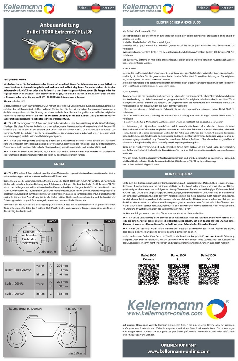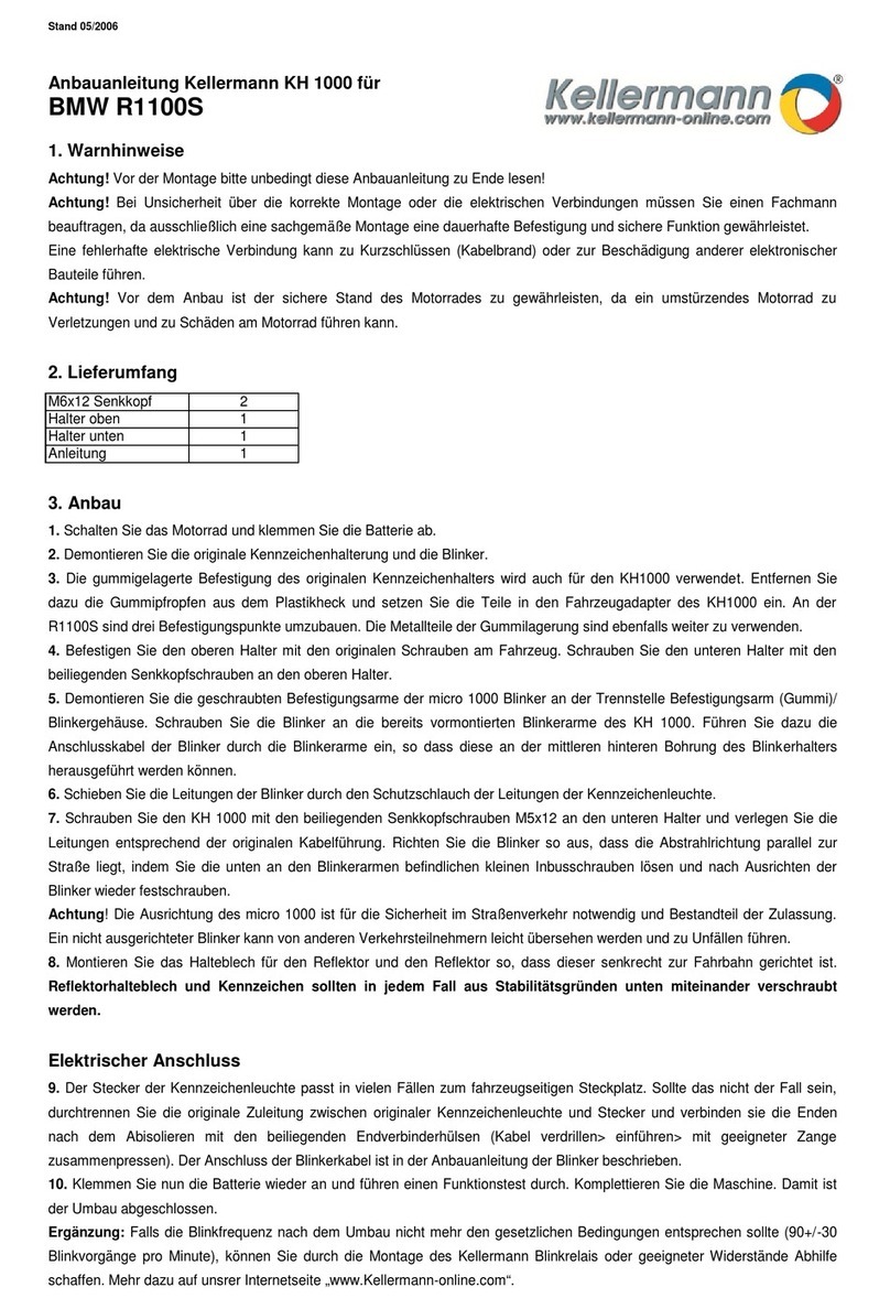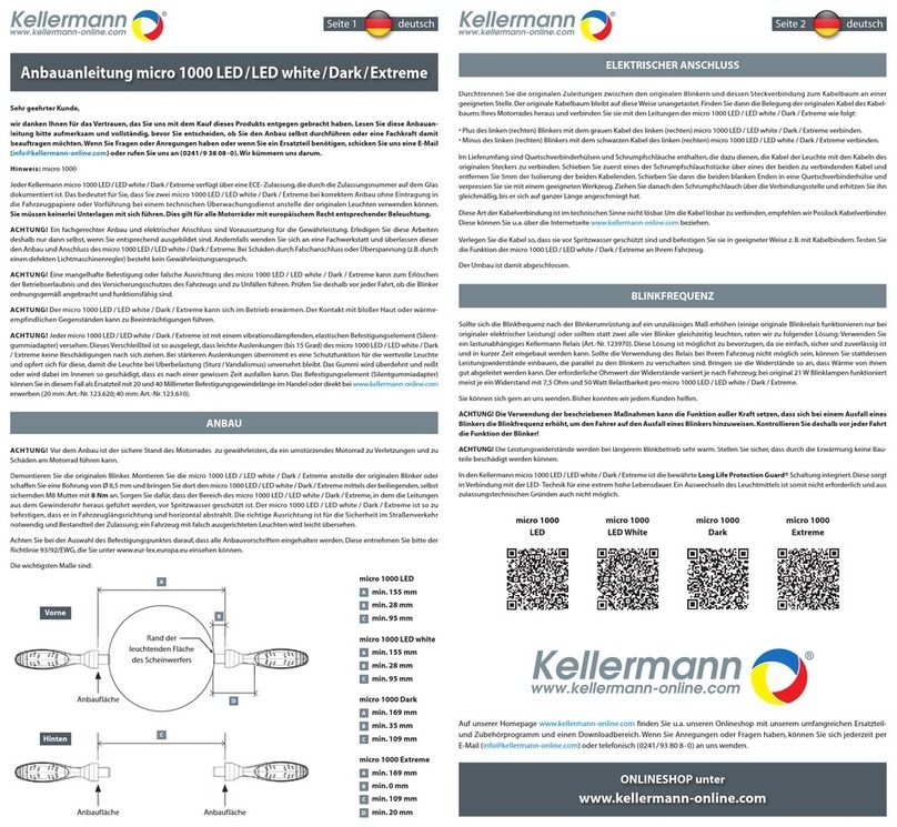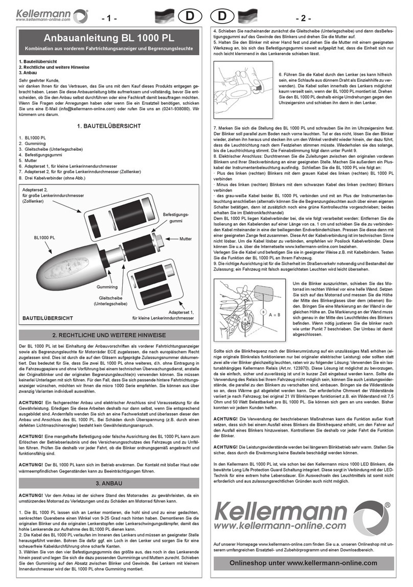
10. Klemmen Sie nun die Batterie wieder an und führen einen Funktionstest durch. Komplettieren Sie die Maschine. Damit ist
der Umbau abgeschlossen.
Ergänzung: Falls die Blinkfrequenz nach dem Umbau nicht mehr den gesetzlichen Bedingungen entsprechen sollte (90+/-30
Blinkvorgänge pro Minute), können Sie durch die Montage eines lastunabhängigen Blinkgebers oder geeigneter Widerstände
Abhilfe schaffen. Mehr dazu auf unserer Internetseite „www.Kellermann-online.com“.
Stand 09/2006
Mounting Instructions Kellermann KH 1000 for
Honda CBR 600RR 2007-
1. Preparation and Warnings
Attention! First of all read this instruction completely!
Warning! If you are uncertain about how to mount the part correctly or how to connect the cables, leave it to an expert - only
proper assembly will ensure a lasting, secure fit. Insecure fastening may lead to accidents. Always make sure that the vehicle
adapter has not come loose before you ride. If it has come loose, tighten it up again. Incorrect electrical connection can lead to
short circuiting (cable fire) or damage to other electronic components.
Warning! Make sure that the motorcycle is standing securely before start mounting - a falling bike can lead to injury and
damage to the bike itself.
2. Scope of delivery
Screw M4x12 4
bracket 124x76x6 L 1
Instructions CBR900RR 1
3. Mounting
1. Switch off the motorbike and remove the seats.
2. Disconnect the battery.
3. Remove the original registration plate holder and indicators.
4. Prepare the covers left and ride as shown on the picture above. Mount the bracket onto the covers. Mount unit on the bike.
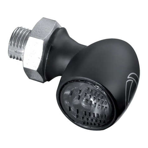
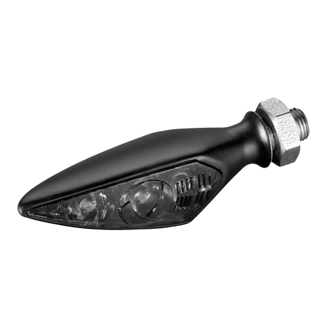
5. Replace the original screw-treaded indicator arms of the micro 1000 indicators with the extended arms supplied. Now fit the
holding arms of the two micro 1000 indicators into the corresponding indicator holders by first feeding the connector cable
through the hollow indicator holder.
6. Feed the connector cable of the indicators through the rubber grommet of the registration plate light.
7. Mount the registration plate holder on the lower bracket using the M5 countersunk screws. Align the indicators parallel to the
road surface. Tighten up the indicators by tightening the allen-head grub screws at the bottom of the indicators.
Warning! Proper alignment of the micro 1000 is essential for road safety and part of the motorcycle’s road use permit. A badly
aligned indicator may be easy to overlook for other road users, leading to accidents.
8. Fit the reflector holding plate and reflector at right angles to the road surface.
Make sure that the fitting is secure by screwing the reflector holder plate and registration plate together.
9. Connect the cables as shown on the picture above. Cut the original supply cables between the plug and taillight, insulate
them off and connect them to the cables on the motorcycle using the end connector sleeves supplied (twist the cables together
> place cable ends into connector sleeves > crimp with appropriate crimping pliers). Connect the indicator cables as described
in the mounting instructions for the indicators.
10. Reconnect the battery and test for function. Once you have mounted all the parts, the work is finished.
Additional note:
If the indicator flash frequency does not match the legal conditions after mounting the indicators (90 ± 30 flashes per minute), a
load-independent indicator controller or suitable resistors may help. See our homepage at www.kellermann-online.com for
further information.
