Lincoln Electric VIKING 4C 2450 Series User manual

IM2068
07/2015
REV00
VIKING™ 4C™2450 SERIES
AUTO-DARKENING HELMETS
4.50X5.25 STANDARD REPLACEMENT LENS
OPERATOR’S MANUAL
GRAPHICS MAY VARY
LINCOLN ELECTRIC EUROPE S.L
c/o Balmes, 89 - 802a, 08008 Barcelona, Spain
www.lincolnelectric.eu
ENGLISH

English English
I
Declaration of conformity
15
Lincoln Electric Europe
Declares that the welding helmets:
Viking 2450 Series
conform to the following directives:
89/686 EWG
and has been designed in compliance with the following standards:
EN 379, EN 166, EN 175
30th June 2015
Pietro Terranova
Accessories Product Manager EMEA
Lincoln Electric Europe S.L, c/o Balmes, 89 – 8°2a, 08008 Barcelona, Spain
12/05

English EnglishII
12/05
THANKS!
For having choosen the QUALITY of the Lincoln Electric products.
•Please Examine Package and Equipment for Damage. Claims for material
damaged in shipment must be notified immediately to the dealer.
•For future reference record in the table below your equipment identification
information. Model Name, Code & Serial Number can be found on the machine
rating plate.
Model Name:
………………...…………………………….…….…………………………………………………………..
Code & Serial number:
………………….…………………………………..
………………….…………………………………..
Date & Where Purchased:
………………….………
…………………………..
………………….…………………………………..
ENGLISH INDEX
Safety ........................................................................................................................... 1
Preparation and Operator Instructions.......................................................................... 2
Helmet Information ....................................................................................................... 3
Specifications ............................................................................................................... 4
Operating Instructions................................................................................................... 5
Cartridge Operation/Features ....................................................................................... 6
Marking......................................................................................................................... 7
Helmet Care and Maintenance ..................................................................................... 8
Shade Guide Settings................................................................................................... 8
Cartridge and Lens Replacement ................................................................................. 9
TroubleShooting Guide............................................................................................... 10
WEEE......................................................................................................................... 11
Spare Parts................................................................................................................. 11
Warranty Information .................................................................................................. 11
Replacement Parts ..................................................................................................... 12
Optional Accessories.................................................................................................. 12

English English1
Safety
01/11
WARNING
This equipment must be used by qualified personnel. Be sure that all installation, operation,
maintenance and repair procedures are performed only by qualified person. Read and understand
this manual before operating this equipment. Failure to follow the instructions in this manual could
cause serious personal injury, loss of life, or damage to this equipment. Read and understand the
following explanations of the warning symbols. Lincoln Electric is not responsible for damages
caused by improper installation, improper care or abnormal operation.
WARNING: This symbol indicates that instructions must be followed to avoid
serious personal injury, loss of life, or damage to this equipment. Protect
yourself and others from possible serious injury or death.
READ AND UNDERSTAND INSTRUCTIONS: Read and understand this
manual before operating this equipment. Arc welding can be hazardous.
Failure to follow the instructions in this manual could cause serious personal
injury, loss of life, or damage to this equipment.
ELECTRIC SHOCK CAN KILL: Welding equipment generates high voltages.
Do not touch the electrode, work clamp, or connected work pieces when this
equipment is on. Insulate yourself from the electrode, work clamp, and
connected work pieces.
ELECTRICALLY POWERED EQUIPMENT: Turn off input power using the
disconnect switch at the fuse box before working on this equipment. Ground
this equipment in accordance with local electrical regulations.
ELECTRICALLY POWERED EQUIPMENT: Regularly inspect the input,
electrode, and work clamp cables. If any insulation damage exists replace the
cable immediately. Do not place the electrode holder directly on the welding
table or any other surface in contact with the work clamp to avoid the risk of
accidental arc ignition.
ELECTRIC AND MAGNETIC FIELDS MAY BE DANGEROUS: Electric current
flowing through any conductor creates electric and magnetic fields (EMF).
EMF fields may interfere with some pacemakers, and welders having a
pacemaker shall consult their physician before operating this equipment.
CE COMPLIANCE: This equipment complies with the European Community
Directives.

English English2
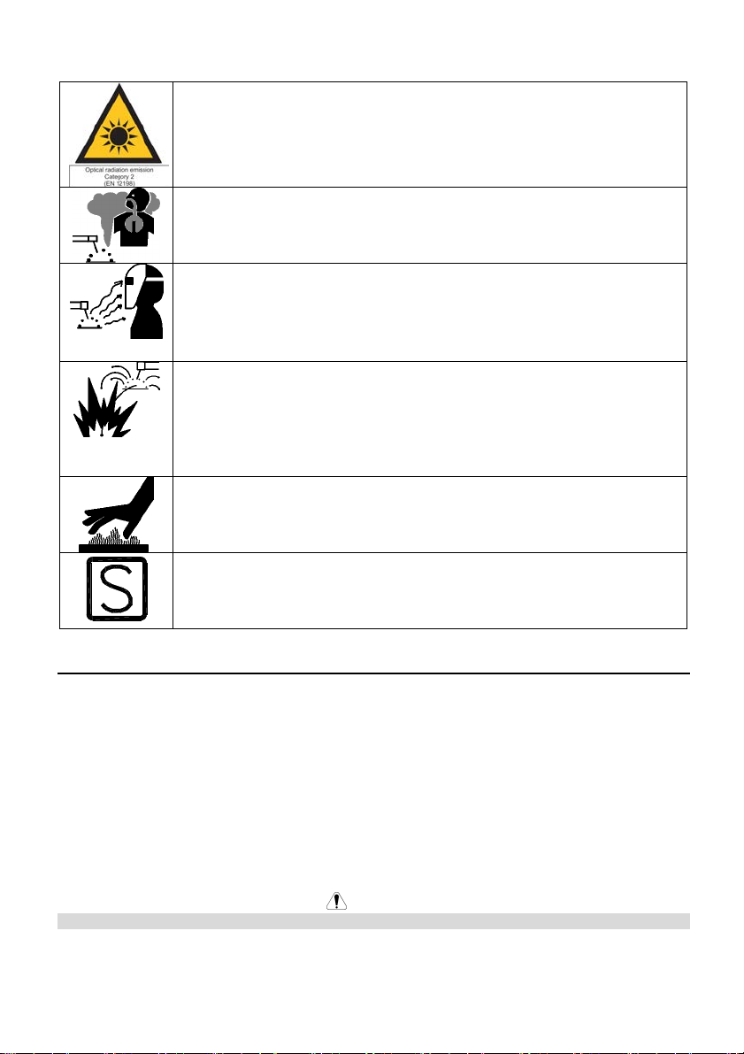
ARTIFICIAL OPTICAL RADIATION: According with the requirements in
2006/25/EC Directive and
EN 12198 Standard, the equipment is a category 2. It makes mandatory the
adoption of Personal Protective Equipments (PPE) having filter with a
protection degree up to a maximum of 15, as required by EN169 Standard.
FUMES AND GASES CAN BE DANGEROUS: Welding may produce fumes
and gases hazardous to health. Avoid breathing these fumes and gases. To
avoid these dangers the operator must use enough ventilation or exhaust to
keep fumes and gases away from the breathing zone.
ARC RAYS CAN BURN: Use a shield with the proper filter and cover plates to
protect your eyes from sparks and the rays of the arc when welding or
observing. Use suitable clothing made from durable flame-resistant material to
protect you skin and that of your helpers. Protect other nearby personnel with
suitable, non-flammable screening and warn them not to watch the arc nor
expose themselves to the arc.
WELDING SPARKS CAN CAUSE FIRE OR EXPLOSION: Remove fire
hazards from the welding area and have a fire extinguisher readily available.
Welding sparks and hot materials from the welding process can easily go
through small cracks and openings to adjacent areas. Do not weld on any
tanks, drums, containers, or material until the proper steps have been taken to
insure that no flammable or toxic vapors will be present. Never operate this
equipment when flammable gases, vapors or liquid combustibles are present.
WELDED MATERIALS CAN BURN: Welding generates a large amount of
heat. Hot surfaces and materials in work area can cause serious burns. Use
gloves and pliers when touching or moving materials in the work area.
SAFETY MARK: This equipment is suitable for supplying power for welding
operations carried out in an environment with increased hazard of electric
shock.
Preparation and Operator Instructions
General
The welding helmets 2450 SERIES secure proper protection of the eyes during welding. They
permanently secure protection against UV and IR radiation and sparks not only in clear but in dark
condition as well.
•Shade degree of 2450 SERIES was matched in such a way to protect your eyes against injury
by the welding arc.
•Direct looking at the welding arc is forbidden. Arc rays are very dangerous. They can cause
painful conjunctivitis and irreparable changes in your pupil.
•Welding helmets 2450 SERIES allow you to observe the welding arc very precisely. You
needn’t flip it up and down during welding. Both your hands are kept free and because of light
weight, the helmet reduces your fatigue and you can gain evident time savings.
WARNING
Batteries not installed please insert before use.
When the arc is striking the filter automatically darkens.

English English3
Before welding
•Check the front cover lens and the front lens frame are securely in place.
•Select the shade level you need for your filter setting by the proper knob.
•Adjust headband so that the helmet is seated on the head as low as possible and near to your
face. Adjust helmet angle when in the lowered position by turning headgear.
•Check the correct operation of the filter
Special Features
•Eyes are always protected against ultraviolet and infrared rays, regardless of the shade level.
•The switching time of the filter from dark to clear state can be adjusted manually. By the
means of a delay time knob the opening time can be adjusted to fast or slow. Before welding
adjust your delay time according to your welding process, in order to protect the eyes against
residual light of the afterglow of the work materials. The fastest opening time is set at 0.1 sec.
Important Note
•The helmets are only to be used to protect the eyes and face from radiation and sparks.
•Lincoln Electric does not accept any liability if the helmet is used for another purpose and
improperly used. Helmets series Viking are not suitable for laser and gas-welding applications.
•Helmet must never be placed on hot surfaces.
•Never open or tamper with the shade filter.
•Protect the filter from liquid and dirty contact.
•Clean the filter surface regularly.
•Always keep sensors and solar cells clean
•Regularly replace the protective lens with Lincoln Electric originals.
WARNING
•Do not leave the workplace with the helmet lowered in position; a bright light surface could
cause the filter darken unexpectedly.
•Helmets should never be used as sunglasses when driving as this could lead to incorrect
identification of the color of traffic lights.
•Materials which may come into contact with the wearer’s skin could cause allergic reactions to
susceptible individuals.
•Eye protectors against high speed particles worn over standard ophthalmic spectacles may
transmit impacts, thus creating a hazard to the wearer .
Helmet Information
This Auto-Darkening Welding Helmet will automatically change from a light state (shade DIN3.5) to
a dark state (shade DIN9-13) when arc welding starts.
The filter automatically returns to a light state when the arc stops.
Match your welding application to the shade indicated on the shade chart. (See Page 8)
• Operating temperature: -10°C ~ 55°C (14°F ~ 131°F).
• Do not use or open the auto-darkening filter if damaged by shock, vibration or pressure.
• Keep the sensors and solar cell clean. Clean the filter cartridge using a soapy water solution and
soft cloth which should be damp but not saturated.
This Auto-Darkening Welding Helmet is designed for use with GMAW, GTAW, MMAW welding, or
Plasma Arc and air carbon arc cutting.

English English4
The cartridge provides protection from harmful UV and IR radiation, in both dark and light states.
The cartridge contains four sensors to detect the light from the welding arc, resulting in the lens
darkening to a selected welding shade.
• Do not use solvents or abrasive cleaning detergent.
• If cover lens is spattered or covered with dirt, it should be replaced immediately.
• Use only replacement parts specified in this manual.
• Do not use the helmet without inside and outside cover lenses properly installed.
Specifications
Model No.: 2450 SERIES ADF
Optical Class 1 / 1 / 1 / 1
LCD Viewing Area 97 x 62mm (3.82 x 2.44in.)
Cartridge size 114 x 133mm (4.50 x 5.25in.)
UV/IR Protection Up to Shade DIN 13 at all times
Arc Sensors 4
Light State Shade DIN 3.5
Variable Welding Shades DIN 5 to 13
Shade Control Dial knob - full adjustment
Power Supply Solar cells - with Batteries
Low Battery Warning Red Light
Battery CR2450 Lithium (2 Required)
Power On/Off Fully automatic
Light to Dark Switching Time 0.00004 sec. (1/25,000 sec.)
Sensitivity Control Variable and Grind
Delay Control (Dark to Light) 0.1 sec. (Short) to 1.0 sec. (Long)
TIG Rating DC >= 2 amps, AC >= 2 amps
Operating Temperature -10°C ~ 55°C (14°F ~ 131°F)
Storage Temperature -20°C ~ 70°C (-4°F ~ 158°F)
Total Weight Black 595g (20.98 Oz.)
Graphic 602g (21.23 Oz.)
Compliance(1) EN166, EN175, EN379
CE, CSA Z94.3, ANSI Z87.1-2010
(1)Headgear compliance with ANSI Z87.1 is without sweatband installed.

English English5
Operating Instructions
Headgear Adjustment
HEAD SIZE ADJUSTMENT: HEADGEAR TIGHTNESS is adjusted by pushing in the Ratchet Knob
and turning to adjust for the desired head size. This knob is located at the back of the helmet.
HEADGEAR CROWN ADJUSTMENTS are made by adjusting for comfort and snapping the pins
into the hole to lock securely in place.
TILT: Tilt adjustment is located on right side of helmet. Loosen the right headgear tension knob and
push the top end of the adjustment lever outward until the lever’s Stop Tab clears the notches. Then
rotate the lever up or down to the desired tilt position. The Stop will automatically engage again
when released locking the helmet into position.
FORE / AFT ADJUSTMENT: Adjusts the distance between the user’s face and lens. To adjust,
loosen the outside tension knobs and slide forward or back to desired position and retighten.
NOTE: Make sure both sides are equally positioned for proper operation
Crown
Adjustment
Ratchet
Knob
Tilt
Adjustment
Fore-Aft
Adjustment

English English6
Cartridge Operation/Features
Variable Shade Control
The shade can be adjusted from shade 6 to 9 and 9 to 13 based upon welding process or
application (refer to shade selection chart on page 8). Shade is adjusted by setting the shade range
switch to the proper range, then use the shade dual scale dial to set the desired shade. The shade
range switch and dual scale dial are located on the ADF cartridge as shown below.
Test
Press and hold test to preview shade selection before welding. When released the viewing window
will automatically return to the light state (3.5 Shade).
Sensitivity Knob
Adjust the light sensitivity by turning the SENSITIVITY knob to the left or right as shown in the figure
below. Turning the knob all the way to the left, the HIGH setting, is typically selected for normal use.
When helmet is used in the presence of excess ambient light or with another welding machine close
by, improved helmet performance can be obtained with a lower setting by turning the knob to the
right to reduce the sensitivity. Grind mode can be selected by rotating the sensitivity knob all the
way to the right until an audible click is heard.
Grind mode is intended for grinding only not for welding.
Delay Knob
This control is designed to protect the welder's eyes from the strong residual rays after welding.
Changing the DELAY knob will vary the dark to light time between 0.1 second (SHORT) to 1.0
second (LONG). LONG setting is recommended for high amperage applications where the weld
puddle is still very bright after the welding arc has ceased and for situations where the filter may be
temporarily blocked from seeing the welding arc.
Power
This ADF cartridge is powered by two replaceable batteries and solar power.
WARNING
Batteries not installed please insert before use.
The batteries are located at the bottom of the ADF cartridge. Replace battery when LOW BATTERY
light is lit. See the specification chart on page 4 for type of battery required.
Shade Dual
Scale Dial
Shade Range
Switch

English English7
Marking
The shell and the auto darkening filter are marked accordingly. Classification for eye and face
protection is following EN379, EN175, EN166.
LINCOLN Auto darkening welding helmet 2450 SERIES
4 / 5 - 8 / 9 - 13 LE 1 / 1 / 1 / 1 379
Light state scale no
Lightest dark state scale no
Darkest state scale no
Manufacturer’s identification
Optical class
Diffusion of light class
Variations in luminous transmittance class
Angle dependence of luminous transmittance class
Number of this standard
Marking on helmet:
"LE EN 175 B" : LE : manufacturer's identification
EN 175: number of this standard
B: resistance to medium energy impact
Marking on front cover lens:
"LE B" : LE : manufacturer's identification
B: resistance to medium energy impact
Marking on Inside cover lens:
"LE 1 B" : LE : manufacturer's identification
1 : optical class
B: resistance to medium energy impact
WARNING
If protection against high speed particles at extremes of temperature is required then the selected
eye-protector should be marked with the letter “T” immediately after the resistance to impact letter. If
the impact letter is not followed by the letter “T” then the eye protector shall only be used against
high speed particles at room temperature
DIN CERTCO Gesellschaft fuer
Konformitaetsbewertung mbH
Alboinstrasse 56
12103 Berlin
Notified body number 0196

English English8
Helmet Care and Maintenance
Cleaning: Clean helmet by wiping with a soft cloth. Clean cartridge surfaces regularly. Do not use
strong cleaning solutions. Clean sensors and solar cells with soapy water solution and a clean cloth
and wipe dry with a lint-free cloth. Do NOT submerge shade cartridge in water or other solution.
Storage: Store in a clean, dry location.
Shade Guide Settings
Recommended shade numbers according to EN 379:2003
CURRENT IN AMPERE
600
14
14
15
600
13
500 500
14
14450 450
13
13 14400 400
12
13
13
350 350
13
12 13300
12
300
12 12
12250 250
11
12
12
225 225
11
11 11200 200
11
11
11
175 175
10
10 10
11
10150 150
10 10
10
125 125
10
9 9
9
100 100
9
9
870 70
8
9
60 60
8
7
40 40
630 30
8
15 15
510 10
6 6
4
2 2
PROCESS
MMAW (STICK
ELECTRODES)
MAG
TIG
MIG
MIG WITH
LIGHT
ALLOYS
AIR-ARC
GOUGING
PLASMA JET
CUTTING
MICROPLASMA
ARC WELDING
If your helmet does not include any one of the shades referenced above, it is recommended you use the next darker shade.

English English9
Cartridge and Lens Replacement
Replacing Front Clear Cover Lens:
WARNING
Replace the front cover lens if it is damaged.
Remove ADF holder assembly per Figure 1. Remove front cover lens from helmet assembly.
Carefully remove gasket from cover lens. Install new cover lens into gasket and assemble to helmet
shell. Make sure to assemble cover lens and gasket into helmet shell the same way as it was
removed.
Replacing Inside Clear Lens:
WARNING
Replace the inside clear lens if it is damaged
Place your fingernail in recess below cartridge view window and flex lens upwards until it releases
from edges of cartridge view window.
Change the Shade Cartridge: Remove ADF holder assembly from helmet shell. See figure 1 for
removal. Flex top end of the ADF holder to allow for ADF cartridge to be removed from frame. Install
new ADF cartridge into frame per figure 2 below. Make sure that the ADF cartridge is inserted in
ADF holder correctly as shown. Install ADF holder assembly into helmet shell.
INSTALLING AN AFTERMARKET MAGNIFYING LENS:
Simply slide the magnifying lens into the short rail located on the sides of ADF holder per Figure 3.
Figure 1 Figure 2 Figure 3

English English10
TroubleShooting Guide
Test your shade cartridge prior to welding by directing the front of the cartridge toward a bright
source of light. Then, using your fingers, rapidly cover and uncover the sensors. The cartridge
should darken momentarily as the sensor is exposed. A torch striker can also be used.
PROBLEM POSSIBLE CAUSE SOLUTION
Difficult to see through filter.
Front cover lens dirty. Clean or replace front cover
lens.
Cartridge dirty.
Clean the Auto-Darkening
cartridge with soapy water
solution and soft cloth.
Filter does not darken when
arc is struck.
Sensitivity is set too low.Adjust sensitivity to required
level.
Front cover lens dirty. Clean or replace front cover
lens.
Front cover lens is damaged.
Check for cracked or pitted
front cover lens and replace
as required.
Sensors are blocked or Solar
panel is blocked.
Make sure you are not
blocking the sensors or solar
panels with your arm or other
obstacle while welding.
Adjust your position so that
the sensors can see the weld
arc.
Grind Mode Selected Make sure proper shade is
selected.
Filter darkening without arc
being struck. Sensitivity set too high.Adjust sensitivity to required
level.
Filter remains dark after
completing a weld. Delay time set too high. Adjust delay time to required
level.
WARNING
ADF is cracked.
Cease (STOP) using this product if this problem exists. UV/IR
protection may be compromised resulting in burns to the eyes
and skin.
Weld spatter is
damaging the
filter.
Missing, damaged, broken,
cracked or distorted front
cover lens.
Replace front cover lens as
needed.

English English11
WEEE
07/06
English
Do not dispose of electrical equipment together with normal waste!
In observance of European Directive 2002/96/EC on Waste Electrical and Electronic
Equipment (WEEE) and its implementation in accordance with national law,
electrical equipment that has reached the end of its life must be collected separately
and returned to an environmentally compatible recycling facility. As the owner of the
equipment, you should get information on approved collection systems from our local
representative.
By applying this European Directive you will protect the environment and human
health!
Spare Parts
08/12
Part List reading instructions
•Use the illustration of assembly page and the end of the catalogue to determine where the part is located
for your particular code.
•Do not use this part list for an item if its code number is not listed. Contact the Lincoln Electric Service
Department for any code number not listed.
First, read the Part List reading instructions above, then refer to the "Replacement Parts" chapter,
that contains a picture-descriptive part number cross-reference.
Warranty Information
SPATTER DAMAGE IS NOT COVERED BY WARRANTY:
Do not use this product without the correct protective clear lenses installed properly on both sides of
the Auto-Darkening Filter cartridge (ADF). The clear lenses supplied with this helmet are properly
sized to work with this product and substitutions from other suppliers should be avoided.

English English12
Replacement Parts
ITEM
PART NO.
DESCRIPTION
QTY
1 KP2898-1 OUTSIDE CLEAR LENS (PKG. QTY: 5) 1
2 KP2932-3 ADF CARTRIDGE FOR VIKING 2450 4C (S27978-113) 1
3 KP2931-1 INSIDE CLEAR LENS (PKG. QTY: 5) 1
4 KP3908-1 HEADGEAR ASSEMBLY (INCLUDING SWEATBAND) 1
5* KP2930-1 SWEATBAND (PKG. QTY: 2) 1
6 S27978-31 REPLACEMENT SHELL (VH11) 1
7 S27978-32 OUTSIDE CLEAR LENS SEAL 1
8 S27978-33 ADF HOLDER 1
*Not illustrated
Optional Accessories
ITEM
PART NO.
DESCRIPTION
QTY
1 KP3046-100 CHEATER LENS 1.00 MAGNIFICATION 1
2 KP3046-125 CHEATER LENS 1.25 MAGNIFICATION 1
3 KP3046-150 CHEATER LENS 1.50 MAGNIFICATION 1
4 KP3046-175 CHEATER LENS 1.75 MAGNIFICATION 1
5 KP3046-200 CHEATER LENS 2.00 MAGNIFICATION 1
6 KP3046-225 CHEATER LENS 2.25 MAGNIFICATION 1
7 KP3046-250 CHEATER LENS 2.50 MAGNIFICATION 1
Table of contents
Other Lincoln Electric Motorcycle Accessories manuals

Lincoln Electric
Lincoln Electric VIKING 2450 Series User manual

Lincoln Electric
Lincoln Electric VIKING 2450 Series User manual

Lincoln Electric
Lincoln Electric SHADE 11 User manual

Lincoln Electric
Lincoln Electric WELDLINE CHAMELEON 4V+ User manual

Lincoln Electric
Lincoln Electric Bester Screen II User manual

Lincoln Electric
Lincoln Electric K3190-1 User manual

Lincoln Electric
Lincoln Electric VIKING 1840 Series User manual

Lincoln Electric
Lincoln Electric IM10055 User manual

Lincoln Electric
Lincoln Electric VIKING 3250D User manual

Lincoln Electric
Lincoln Electric VIKING 5X4 SHADE 11 User manual