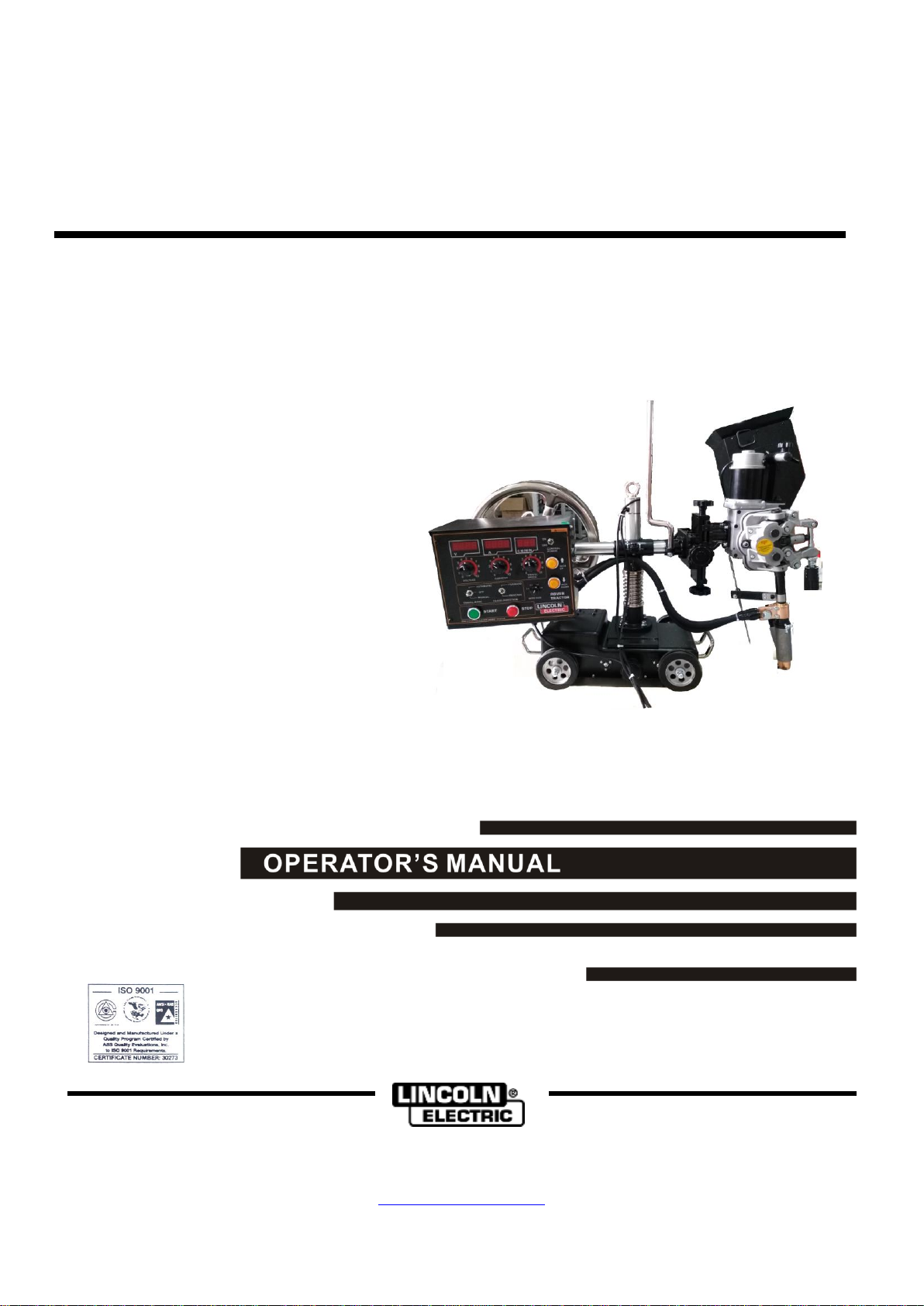
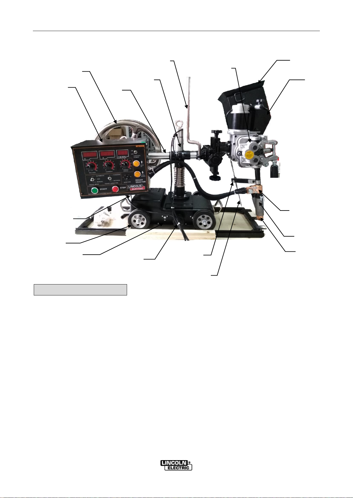
Lincoln Electric ROVER K60068-5 User manual

Rev. 01
IM8001-6
Feb,2017
Rev. 01
ROVERTM TRACTOR
For use with machine Code: K60068-5 / Code No. 76306
•World’s Leader in Welding and Cutting•
THE SHANGHAI LINCOLN ELECTRIC CO.,LTD
No. 195, Lane 5008, Hu Tai Rd. Baoshan, Shanghai, PRC 201907
www.lincolnelectric.com.cn
Safety Depends on You
Lincoln arc welding and cutting
equipment is designed and built with
safety in mind. However, your overall
safety can be increased by proper
installation and thoughtful operation on
your part. DO NOT INSTALL,
OPERATE OR REPAIR THIS
EQUIPMENT WITHOUT READING
THIS MANUAL AND THE SAFETY
PRECAUTIONS CONTAINED
THROUGHOUT. Most importantly, think
before you act and be careful.
Copyright © 2017The Shanghai Lincoln Electric Company

Rev. 01
Thank you for selecting QUALITY Lincoln Electric products.
Please examine the packaging and equipment for damage. Claims for material
damaged in shipment must be notified immediately to the authorized dealer from whom
you purchased the machine.
For future reference, please record your equipment identification information in the
table below. Model Name, Code & Serial Number can be found on the machine rating
plate.
Model Name
ROVERTM TRACTOR
Code & Serial number
K60068-5
Date & Where Purchased
Authorized Dealer’s Chop
Declaration of conformity
THE SHANGHAI LINCOLN ELECTRIC CO., LTD
Designed in conformance with the following norm:
GB15579-5
EN 60974-5
EN 60974-10
THE SHANGHAI LINCOLN ELECTRIC CO.,LTD
No. 195, Lane 5008, Hu Tai Rd, Shanghai, PRC 201907

iSAFETY i
RoverTMTractor
ARC WELDING CAN BE HAZARDOUS. PROTECT YOURSELF AND OTHERS FROM
POSSIBLE SERIOUS INJURY OR DEATH. KEEP CHILDREN AWAY. PACEMAKER WEARERS
SHOULD CONSULT WITH THEIR DOCTOR BEFORE OPERATING EQUIPMENT.
BE SURE THAT ALL INSTALLATION, OPERATION, MAINTENANCE AND REPAIR
PROCEDURES ARE PERFORMED ONLY BY QUALIFIED INDIVIDUALS.
WARNING
ELECTRIC AND
MAGNETIC
FIELDS may be
dangerous.
1.a Electric current flowing through any conductor
causes localized Electric and Magnetic Field
(EMF). Welding current creates EMF fields
around welding cables and welding machines.
1.b EMF fields may interfere with some pacemakers,
and welders having a pacemaker should consult
their physican before welding.
1.c All welders should use the following procedures in
order to minize exposure to EMF fields from the
welding circuit:
1.c.1 Route the electrode and work cables
together –Secure them with tape when
possible.
1c.2 Never coil the electrode lead around your
body.
1.c.3 Do not place your body between the
electrode and work cables. If the electrode
cable is on your right side, the work cable
should also be on your right side.
1.c.4 Connect the work cable to the workpiece as
close as possible to the area being
welded.
ARC RAYS can burn.
2.a Use a shield with the proper filter and cover
plates to protect your eyes from sparks and the
rays of the arc. Headshield and filter lens should
conform to ANSI Z87. I standards.
2.b Use suitable clothing made from durable flame-
resistant material to protect your skin andthat of
your helpers from the arc rays.
2.c Protect other nearby personnel with suitable,
non-flammable screening and/or warn them not
to watch the arc nor expose themselves to the
arc rays or to hot spatter or metal.
ELECTRIC SHOCK
can kill.
3.a Electrode and work (or ground) circuits are
electrically “hot” when the welder is on. Do not
touch these “hot” parts with your bare skin or wet
clothing. Wear dry, hole-free gloves to insulate
hands.
3.b Insulate yourself from work and ground using dry
insulation. Make certain the insulation is large
enough to cover your full area of physical contact
with work and ground.
In addition to the normal safety precautions, if
welding must be performed under electrically
hazardous conditions (in damp locations or while
wearing wet clothing; on metal structures such as
floors, grating or scaffolds, when in cramped
positions such as sitting, kneeling or lying down, if
there is a high risk of unavoidable or accidental
contact with the workpiece or ground) use the
following equipment:
Semiautomatic DC Constant Voltage (Wire)
Welder.
DC Manual (Stick) Welder.
AC Welder with Reduced Open Circuit Voltage.
3.c In semiautomatic or automatic wire welding, the
electrode, electrode reel, welding head, nozzle or
semiautomatic welding gun are also electrically
“hot”.
3.d Always be sure the work cable makes a good
electrical connection with the metal being
welded. The connection should be as close as
possible to the area being welded.
3.e Ground the work or metal to be welded to a good
electrical (earth) ground.
3.f Maintain the electrode holder, work clamp,
welding cable and welding machine in good, safe
operating condition. Replace damaged
insulation.
3.g Never dip the electrode in water for cooling.
3.h Never simultaneously touch electrically “hot”
parts of electrode holder to two welders because
voltage between the two can be total of the open
circuit voltage of both welders.

ii SAFETY ii
RoverTMTractor
FUMES AND GASES
can be dangerous.
4.a Welding may produce fumes and gases
hazardous to health. Avoid breathing these
fumes and gases. When welding, keep your
head out of the welding fumes. Use enough
ventilation and/or exhaust at the arc to keep
fumes and gases away from the breathing zone.
When welding with electrodes which require
special ventilation such as stainless or hard
facing (see instructions on container or
MSDS) or on lead or cadmium plated steel
and other metals or coatings which produce
highly toxic fumes, keep exposure as low as
possible and below Threshold Limit Values
(TLV) using local exhaust or mechanical
ventilation. In confined spaces or in some
circumstances, outdoors, a respirator may be
required. Additional precautions are also
required when welding on galvanized steel.
4.b Do not weld in locations near chlorinated
hydrocarbon vapors coming from degreasing,
cleaning or spraying operations. The heat and
rays of the arc can react with solvent vapors to
form phosgene, a highly toxic gas, and other
irritating products.
4.c Shielding gases used for arc welding can
displace air and cause injury or death. Always
use enough ventilation, especially in confined
areas, to insure breathing air is safe.
4.d Read and understand the manufacturer’s
instructions for this equipment and the
consumables to be used, including the material
safety data sheet (MSDS) and follow your
employer’s safety practices. MSDS forms are
available from your welding distributor or from
the manufacturer.
FOR
ELECTRONICALLY
powered equipment.
5.a Turn off input power using the disconnect switch
at the fuse box before working on the equipment.
5.b Install equipment in accordance with national
standards, all local standards and the
manufacturer’s recommendations.
5.c Ground the equipment in accordance with the
national standards and the manufacturer’s
recommendations.
WELDING SPARKS
can cause fire or
explosion.
6.a Remove fire hazards from the welding area. If
this is not possible, cover them to prevent the
welding sparks from starting a fire. Remember
that welding sparks and hot materials from
welding can easily go through small cracks and
openings to adjacent areas. Avoid welding near
hydraulic lines. Have a fire extinguisher readily
available.
6.b When not welding, make certain no part of the
electrode circuit is touching the work or ground.
Accidental contact can cause overheating and
create a fire hazard.
6.c Do not heat, cut or weld tanks, drums or
containers until the proper steps have been
taken to insure that such procedures will not
cause flammable or toxic vapors from
substances inside. They can cause an explosion
even though they have been “cleaned”.
6.d Sparks and spatter are thrown from the welding
arc. Wear oil free protective garments such as
leather gloves, heavy shirts, cuffless trousers,
high shoes and a cap over your hair.
CYLINDER may
explode if damaged.
7.a Use only compressed gas cylinders containing
the correct shielding gas for the process and
properly operating regulators designed for the
gas and pressure used. All hoses, fittings, etc.
should be suitable for the application and
maintained in good condition.
7.b Always keep cylinders in an upright position
securely chained to an undercarriage or fixed
support.
7.c Cylinders should be located:
Away from areas where they may be struck or
subjected to physical damage.
A safe distance from arc welding or cutting
operations and any other source of heat,
sparks, or flame.
7.d Never allow the electrode, electrode holder or
any other electrically “hot” parts to touch a
cylinder.
7.e Keep your head and face away from the cylinder
valve outlet when opening the cylinder valve.
7.f Valve protection caps should always be in place
and hand tight except when the cylinder is in use
or connected for use.

A-1 TECHNICAL SPECIFICATIONS A-1
RoverTMTractor
TECHNICAL SPECIFICATIONS---ROVERTM Tractor
INPUT VALUE
ROVERTM TRACTOR
Standard Voltage/Phase/Frequency
110V AC(±10%)/1/50 or 60 Hz
INPUT AMPERES
2.6 A
RATED OUTPUT
ROVERTM TRACTOR
DUTY CYCLE
60%
100%
AMPERES
1200 A
1000 A
RATED VALUE
WIRE DIAMETER
2.4 ~ 4.8 mm
WIRE FEED RATE
15 ~ 150 m/h
TRAVEL SPEED RANGE
6 ~ 72 m/h
PHYSICAL DIMENSIONS
ROVERTM TRACTOR
DEPTH
1080 mm
WIDTH
480 mm
HEIGHT
740 mm
WEIGHT
55 Kg ( W/O wire)
TEMPERATURE RANGES
Operating temperature
-40°C ~ +40°C
Storage temperature
-40°C ~ +55°C
OTHER PARAMETERs
Adjustable height of cross beam
70mm
Adjustable distance of tractor head
100mm×100mm×70mm(up and down、left and right、front and back)
Rotatable angle of cross beam around
vertical column
±90°
Tractor head inclination
±45°
Torch inclination
±45°
Flux container volume
6L
inner diameter of wire spool
φ300
Wire spool capacity
25kg
For any maintenance or repair operation it is recommended to contact the nearest technical service center or
directly consult the machine division of the Shanghai Lincoln Electric Co. Ltd.. Maintenance or repairs
performed by unauthorized service centers or personnel will void the manufacturer’s warranty.

A-2 INSTALLATION A-2
RoverTMTractor
SAFETY PRECAUTIONS
Read the entire installation section before starting
installation.
Electric shock can kill
Only qualified personnel
should install this machine
Turn the input power OFF at
the disconnect switch of fuse
box before installing or
working on the equipment
Do not touch electrically hot parts.
SELECT SUITABLE LOCATION
This power source should not be subjected to rain, nor
should any parts of it be submerged in water. Doing so
may cause improper operation as well as pose a safety
hazard. The best practice is to keep the machine in a
dry, sheltered area.
The bottom of machine must always be placed on a
firm, secure, level surface. There is a danger of the
machine toppling over if this precaution is not
taken.
Place the welder where clean cool air can freely
circulate in through the side and back louvers and out
through the case bottom. Water dust or any foreign
material that can be drawn into the welder should be
kept at minimum. Failure to observe these precautions
can result in excessive operating temperatures and
nuisance shutdowns.
Locate the ROVERTM machine away from radio
controlled machinery. Normal operation of the welder
may adversely affect the operation of RF controlled
equipment, which may result in bodily injury or damage
to the equipment.
STACKING
ROVERTM can’t be stacked.
WELDING CABLE AND
CONTROL CABLE CONNECTION
Only a qualified electrician should connect the
input leads to the ROVERTM. Please use lincoln
electric offered quality control cable to connect
to power source with ROVERTM. If you don’t
use qualified control cable as Shanghai Lincoln
Electric standard, it will effect machine
preformance and body injury.
WARNING
WARNING
CAUTION

A-3 INSTALLATION A-3
RoverTMTractor
ROVERTM Tractor Parts List
▅Additional Infromation
▲The tractor is composed of tractor base, vertical column, rotary part of the cross
beam, base plate hand wheel,wire feeder reductor,tractor head bracket
assembly,flux hopper assembly,wire spool assembly and control box;
Acceptance of packing
●Please check whether the package is damaged when you receive the goods.
●Please open the package for inspecting and accepting the tractor, the specifica-
tion and quality of the tractor and the accessory is as below. SEE《ROVERTM
Tractor Packing List 》
Wire Spool
Control Box
Beam
Wire
Guide
frame
Vertical
Column
Clutch Handle
Travelling
Wheel
Wave
Shaped
Hand Wheel
Tractor
Base
Current-
Conducting
Plate
Pointer
Locking
Screw for
Pointer
Flux Cone Body
Flux Cone
Flux
Hopper
Flux Filter
Mesh
Feed Head
assembly

A-4 INSTALLATION A-4
RoverTMTractor
ROVERTM Tractor Packing List
* : Defaulted parts on the tractor.
ROVERTM Tractor Connection Diagram
Standard Accessory
Note:therightsizeofwirefeederdriverollandcontacttipisasbelow.
Name
Size
QTY
Note
Drive roll
Φ3/Φ4 *
Φ4.2/Φ5
2 each
Including the original two
Contact tip
Φ3、Φ4 *、Φ5
1
Including the original one
Special tube
spanner
1
For rotating the angle of
the bracket
Dual head wrench
14x17
1
For adjusting the position
of the tractor head
Fuse
4A 250V
2
Figure 1 welding cable and control cable connection(DC+)
Power Source
Workpiece
Welding cable to
shunt
Control cable
Ground cable

A-5 INSTALLATION A-5
RoverTMTractor
Turn off ROVERTMTractor.
Turn off power source,connect welding
cable and control cable as Figure 1. The
control cable uses lincoln standard 9 pin
connector, it’s compatible with LT-7TM
Tractor connector .
Please make sure the output toggle switch
is on CC mode.
Choose sufficient size of welding cable
according to your welding parameter. If your
do not use suitable size welding cable, it will
effect your welding quality. If the welding
cable is too thin,maybe it will cause fire.
For safety and welding quality reason,
please make sure all the connections are
tightly metal-to-metal electrical contacted. If
not, it will injury output stud and affect
welding performance.
Turn off ROVERTMTractor and the power source.
Connect welding cable and control cable as Figure 2. Set the polarity switch at “-”on power source.
Open the control box, pull out the J3 plug (white wire), and plug in the grey wire one.
warning
Figure 2 welding cable and control cable connection(DC-)
Power Source
Welding cable to
shunt
Control cable
Ground cable
J3

A-6 INSTALLATION A-6
RoverTMTractor
Note.The two steps above should be recovered, when go back to DC+ welding mode.
Press “INCH UP”& “INCH DOWN”buttons and then power on the tractor. Press the “INCH UP”four times, and
“INCH DOWN”four times. Let the display window show like below,to enter the parameter setting mode.
Push “STOP”button,let the right side display window show”E”,to enter into edit mode.Push “INCH DOWN”button to
select the weld polarity(0=DC+;1=DC-), then restart the tractor.
Select the right size welding cable according the welding process.
A
V

A-7 INSTALLATION A-7
RoverTMTractor
Construction of the tractor and function of various components.
1.Control box 2.Wire spool 3.Cross beam 4.Adjustable tightening screw(1) 5.Vertical
column 6. M8 Hexagonal stud 7.Wire guide frame 8.Feed head adjustment hand wheel
9.wire feeding motor 10.Feeder head bracket assembly 11.Flux hopper 12.Flux filter mesh
13. M8 hexagonal nut 14.Star shaped hand wheel 15.Adjustable tightening handle 16.Wave
shaped hand wheel 17.Straightening wheel 18.Flux shutter 19.tractor base 20.Pressuer
regulation knob 21.Clutch handle 22.Torch bar 23.Rubber flux hose 24.Conducting plate
25.Triangle flux container 26.Wire feeder reductor 27.Indictor 28.Flux exit tube
29.Travelling wheel 30. Adjustable tightening screw(2) 31.Drawing frame of the wire spool
▅Function of the parts
▲Travel of the tractor
●The tractor will travel automatically by moving the clutch handle○
21to
“auto”shift (closing the clutch),the tractor will stop travelling by moving
the clutch handle○
21to “manual”shift(releasing the clutch)and it can be
pushed forward of backward manually.
Lift
bail

A-8 INSTALLATION A-8
RoverTMTractor
▲Movement of the vertical column
●The vertical column can be moved for 70mm by rotating the wave-shaped hand
wheel○
16 ;
▲Up and down of the cross beam
●The cross beam can move upward relying on the spring force itself or downward
by pressing down spring for 70mm when loosening the adjustable tightening
screw(2)○
30
▲Position adjustment of the tractor feed head
●The tractor feed head can be moved upward/downward or leftward/rightward for
100mm by rotating the Feed head adjustment hand wheel○
8
▲Transversal movement of the tractor head
●The tractor can move together with the cross beam transversally for 100mm by
loosening the adjustable tightening screw○
4
Attention
● The surface for the tractor working on should
be even, paint residue, iron scrap and
rubbish should be cleared away.
●The rail should be parallel to the workpiece.
Clutch handle○
21

A-9 INSTALLATION A-9
RoverTMTractor
up
down
▲The rotatable angle of the cross beam around vertical column is±90°
●The cross beam can rotate around vertical column ○5±90°by loosening the
adjustable tightening handle(2)○
30
▲Tractor head inclination ±45°
●The tractor head can totate ±45°by cloosening that M8 hexagonal stud on the
upper part of the rotary disk of the Feed head adjustment hand wheel○
8.
(Another M8 hexagonal stud on the lower part of the rotary disk of the base plate
has been pre-set, there is no need to make any adjustment.)
▲Torch inclination ±45°
●The tractor head bracket assembly can rotate together with the torch for ±45°
by loosening the 2 knurled screw (no need to disassemble) on the tractor head bracket
Vertical column○
5
Cross
beam○
3
Feed head adjustment hand wheel○
8
Adjustable tightening screw○
4
Adjustable tightening screw○
30
Wave-shaped hand wheel○
16
spring
M8 hexagonal stud ○
A on the upper
part
Tractor head
M8 hexagonal stud○
B on the lower
part

A-10 INSTALLATION A-10
RoverTMTractor
assembly, moving away protective shield, loosening 2 M8 hexagonal nut on the tractor
head bracket assembly with the special tube spanner. When the desired angle is
rotated to the position, restore the protective shield to it’s original position and tighten
the 2 knurled screw.
▲Adjustment of the damping of the wire reel
shaft
●The damping force has been preset. In case adjustment is made,please follow
the following procedures.
①move the cap→②tighten the inner hexagonal screw to increase damping,
loosen the hexagonal screw to reduce damping →③re-load the cap.
▲Rotatable angle of the control box
●The control box can be rotated horizontally by loosening the star shaped screw
on the top of the control box.
Important reminder !
The dust in the interface between the
tractor head bracket assembly and the
wire feed reductor has to be cleared,
otherwise, the dust may enter into the
wire feeder reductor from the screw
holes during the rotation of the tractor
head bracket assembly and the
torch,which will result in the wearing of
the gears and other parts of the reductor.
2-M8 hexagonal nut
Star shaped screw
Cross beam
Special tube spanner
Protective shield
Knurled screw
Torch
abrasionresistant washer
Spring
washer
inner hexagonalscrew
▲Tighten the inner hexagonal
screwtoincreasedamping
▲Loosentheinnerhexagonal
screwtoreducedamping

B-1 OPERATION B-1
RoverTMTractor
Preparation Before Welding
▅Please operate the tractor after connecting it to the power source
according to following procedures.
●Clear the welding area, clean away sundries such as
rubbish, oil and dirty.
●Please make sure the rail is at same level as the work-
piece or parallel.
●Please check and make sure that the driver roll is suita-
ble for the wire size at the end.
Procedures to load wire feeder rolls:
Remove knurled screw→ automatic push-out of the protective shield and gear casing→
take off copper washer→ remove wire feeder roll→ check the specification of the wire
feeder roll→ clear dust from the wire feeder axis and apply some lubrication grease→ load
the 2 rolls of the same specification with the wires→ re-load copper washer→ close the
gear casing→ load the protective shield→ tightening knurled screw.
●Load wires
1. Pull out and push down the block of the damping wire reel shaft; 2. Take off the wire
spool; 3. Unscrew the cap with ears; 4. Take off the wire spool fixing cover
5. Load the wires into the wire spool fixing cover; 6. Put on wire spool out coverer
Important reminder !
●When replacing the wire feeder roll-
ers, please make sure that the two
wire feeder grooves are at the same
specification and wipe away the dust
on the wire feeder axis, use the lu-
brication grease to prolong the ser-
vice life of the wire feeder rolls.
●Please add one copper washer each
on the front and back axis after the
wire feeder rolls are installed.
●After the wire feeder rolls are re-
placed, be sure to close the gear
casing and the protective shield,
tighten the 2 knurled screws to make
the interface between the gear cas-
ing and wire feeding bracket assem-
bled tightly. The gear casing serves
as both the protective casing and the
brace for the wire feeder axis, it
must be re-loaded after dissembled.
● The thickness of the copper washer
must be strictly observed to prevent
bad results.
Round pin
bracket
gear
Wire feeding roll shaft
Feeding rolls
Copper washer
Gear casing
Knurled screw
Copper bushing
Protection
board
Copper bushinbg

B-2 OPERATION B-2
RoverTMTractor
7. Screw in the cap with ears; 8. Re-load the wire spool; 9. Restore the block to its
original position
▅As to how to adjust the damping force, please refer to the adjustment of the
damping of the wire reel shaft
▅Primary adjustment of the tractor head position
▲ Adjust the Feed head adjustment hand wheel to move the torch to the weld seam
▲ When rotating the tractor head, please refer to tractor head inclination ±45°- PAGE A-9
▲ When deflecting the torch, please refer to torch inclination±45°- PAGE A-9
Important reminder!
The block of the damping wire
spool shaft has to be returned to
it’s original position to prevent
wire spool from falling off.
Important reminding!
In case to adjust the angle of the
tractor head, loosen that M8
hexagonal stud○
Aon the upper of
the rotary disk of the base plate.
Please hold the tractor head when
doing so to prevent the tractor head
from falling over due to its own
weight and damaging the flux exit
tube.
Important reminding!
The dust in the interface between
the tractor head bracket assembly
and the wire feeder reductor has to
be cleared when deflecting the torch,
otherwise, the dust may enter into
the wire feeder reductor from the
screw holes during the rotation of the
tractor head bracket assembly which
will result in the wearing of the gears
and other parts of the reductor.
Feed head adjust-
ment hand wheel
M8 hexagonal stud○
Aon the upper
Tractor head
workpiece
Torch bar
Flux exit tube
Damping wire reel shaft
Block
Wire spool
fixing cover
wire
Cap with ears
Wire spool Outer cover

B-3 OPERATION B-3
RoverTMTractor
Attention
The torch inclination should be no more than ±45°,in case the
angle is too big, the feeding angle of the wire will be changed and
there will be more obstruction to affect the feeding results and it
may burn feeding motor in worst case.
▲Adjusting the position of the wire guide frame
●Draw out wires from the wire spool and guide it all the way to feeding roller through the wire
guide fame, pulley and guide in nozzle. Tighten the hexagonal screw to fix the wire
guide frame after proper adjusting.
▲Press down wires tightly
●There is adjusting screw knurled tube on the pressure regulating handle with symbols 3,45
on it. The symbols 3,4,5show the positions that the cap is to be adjusted to for wire
diameters Φ3、Φ4 andΦ5 accordingly. Please regulate the cap to its proper position
so that the pressure regulating arm can be pushed easily.
●Pressure regulating knob: tighten the knob clockwise to increase the tightening force,
anticlockwise to reduce the tightening force.
▲Regulating the straightening roller to straighten the wires
●Release the pressure regulating knob,rotate the hexagonal knob, push in the straightening
roller, press down the manual feeding button to make the straightening roller press tightly on
the wires to start the feeding process. Close the pressure regulating knob and continue rotating
hexagonal knob until the straightness of the wires meets the welding requirement measured by
the eyes.
Warning
●Do not wear glove when guiding or
replacing the wires
●Do not touch the gears when in rotating
Important reminding!
The ideal pressure on the wire should be
such that guarantees normal feeding of
the wire and makes no slip. The scale of
the pressure regulating knob should be
set around 2-3, pressuring wires too
tightly will increase the power
consumption of the motor.
Wire drawing
frame
Wire guide frame
pulley
Guide in
nozzle
Drive roll
Hexagonal nut
Draw away
Hexagonal knob
Straightening roll
Wire
Pressure roller frame
Pressure regulating knob
Cylindrical screw tube
knurled regulating
Pressure regulating knob

B-4 OPERATION B-4
RoverTMTractor
▲Reference value of the straightness of the wire
The straightness of the wire sticking out within 100mm after straightening should be no
more than 2.5mm.Please refer to the following chart.
▲Check the position and angle of the flux hopper
● Release the star shaped hand wheel to adjust the position of the flux hopper.
● Release the adjustable tightening handle to adjust the angle of the flux hopper.
● Adjust the position and the angle of the triangle flux container to make it suitable for
that of the flux hopper, which will ensure smooth flux exit.
● Adjust flux container switch to make flux barely cover the contact tip and the weld
seam,the welding speed could be adjusted by eye measurement.
▲Set welding current, voltage and speed
●The welding current, voltage and speed is pre-set accordingly to the thickness of the
work piece and welding process requirement.
Straightness
reference value
Spec
Reference
value H
Φ6
1.3
Φ5
1.0
Φ4
0.6
Φ3
0.4
Important
reminding!
Over-straightening of the
wires will cause wires to
bend in opposite direction!
Important reminding!
Flux filter mesh function is keep the flux all
same size and keep the flux easy through
flux exit tube.
Note
The arc distance of 5-10mm between the
contact tip and bottom surface of the flux
exit tube has been set before ex-works.
Flux hopper
Flux shutter
Contact tip
Triangle flux
container
Flux exit tube
Flux filter mesh
Star shaped
hand wheel
open

B-6 OPERATION B-6
RoverTMTractor
▲Press down the power button to light the indication lamp and power on the
tractor
● Move the manual/automatic shift to manual to start feeding the wires manually,
letting wires go through the torch bar and into the contact tip for the pre-set length.
▅Minor adjustment of the position of the tractor head
▅
▲Minor adjust the welding wire to the middle of the weld seam
●Observe whether the welding wire is positioned to the middle of the weld seam,
rotate the Feed head adjustment hand wheel until it is adjusted to the desired po-
sition.
▲Adjust the pointer to point at the weld seam
●After the minor adjustment, the position of the welding torch and the weld seam
have been set, release the fixing nut of the indicator to adjust it’s position 10-
15mm higher than that of the work piece, trigger the indicator to point at the weld
seam and tighten the fixing nut again.
Tractor head
Feed head adjustment hand
wheel
M8 hexagonal stud on the upper
workpiece
torch
Triangle flux container
pointer
Fixing nut of the pointer

B-6 OPERATION B-6
RoverTMTractor
▅Start to weld
▲ Move the “manual/automatic” shift to “automatic” and press the “start” but-
ton until the arc is ignited to start the welding.
▲Power offer when the welding is finished
●Push the “stop” button to end the welding when the torch reaches the end of the weld
seam. Close the shutter of the flux hopper and power off. Move the clutch handle on the
tractor base to “manual” and drag the tractor out of the welding area.
Motor and welding current collecting connection illustrated.
Detail infromation,see Figure 2 and Figure 3
Control cable port illustrated
Detail information,see Figure 4 and A.1
DC1000 control out stud see Figure 5
6
4
5 2
3
1
Figure 2 motor and welding current collecting socket(under control box)
Important reminding!
Observe whether the indicator is to the
middle of the weld seam during welding
process and make adjustment
immediately in case of deflection.
Clutch handle
Flux shutter
This manual suits for next models
1
Table of contents
Other Lincoln Electric Tractor manuals
Popular Tractor manuals by other brands

McConnel
McConnel ROBOPOWER 111300001 Operator's manual

New Holland
New Holland SmartTrax T8.320 Service manual

Daedong
Daedong KIOTI EX35 manual

New Holland
New Holland T9020 Operator's manual

Haybuster
Haybuster Balebuster 2564 operating instructions

Husky
Husky BOLENS 194-01 Owner's operation and maintenance manual