manuals.online logo
Brands
  1. Home
  2. •
  3. Brands
  4. •
  5. Lincoln Electric
  6. •
  7. Welding System
  8. •
  9. Lincoln Electric IDEALARC IM318-B User manual

Lincoln Electric IDEALARC IM318-B User manual

This manual suits for next models

1

Other Lincoln Electric Welding System manuals

Lincoln Electric RANGER 250 User manual

Lincoln Electric

Lincoln Electric RANGER 250 User manual

Lincoln Electric 12674 User manual

Lincoln Electric

Lincoln Electric 12674 User manual

Lincoln Electric PRECISION TIG 275 TIG 275 User manual

Lincoln Electric

Lincoln Electric PRECISION TIG 275 TIG 275 User manual

Lincoln Electric Harris 62-E User manual

Lincoln Electric

Lincoln Electric Harris 62-E User manual

Lincoln Electric POWER FEED 15M IM761 User manual

Lincoln Electric

Lincoln Electric POWER FEED 15M IM761 User manual

Lincoln Electric POWER WAVE S500 CE User manual

Lincoln Electric

Lincoln Electric POWER WAVE S500 CE User manual

Lincoln Electric IDEALARC IM10018-A User manual

Lincoln Electric

Lincoln Electric IDEALARC IM10018-A User manual

Lincoln Electric LINC FEED 40 User manual

Lincoln Electric

Lincoln Electric LINC FEED 40 User manual

Lincoln Electric AC-225C User manual

Lincoln Electric

Lincoln Electric AC-225C User manual

Lincoln Electric DUAL VANTAGE 700 (AU) User manual

Lincoln Electric

Lincoln Electric DUAL VANTAGE 700 (AU) User manual

Lincoln Electric INVERTEC V350-PRO CE User manual

Lincoln Electric

Lincoln Electric INVERTEC V350-PRO CE User manual

Lincoln Electric LN-10 HEADS & CONTROLS IM587-B User manual

Lincoln Electric

Lincoln Electric LN-10 HEADS & CONTROLS IM587-B User manual

Lincoln Electric CITOCUT 25i User manual

Lincoln Electric

Lincoln Electric CITOCUT 25i User manual

Lincoln Electric INVERTEC POWER WAVE 450 IM524-D User manual

Lincoln Electric

Lincoln Electric INVERTEC POWER WAVE 450 IM524-D User manual

Lincoln Electric FlexCool 35 User manual

Lincoln Electric

Lincoln Electric FlexCool 35 User manual

Lincoln Electric NA-3 User manual

Lincoln Electric

Lincoln Electric NA-3 User manual

Lincoln Electric PRO 100 User manual

Lincoln Electric

Lincoln Electric PRO 100 User manual

Lincoln Electric RANGER IM511-D User manual

Lincoln Electric

Lincoln Electric RANGER IM511-D User manual

Lincoln Electric IDEALARC R3R 375-I User manual

Lincoln Electric

Lincoln Electric IDEALARC R3R 375-I User manual

Lincoln Electric SP-170T IM794 User manual

Lincoln Electric

Lincoln Electric SP-170T IM794 User manual

Lincoln Electric INVERTEC V450-PRO User manual

Lincoln Electric

Lincoln Electric INVERTEC V450-PRO User manual

Lincoln Electric RANGER 225 GXT User manual

Lincoln Electric

Lincoln Electric RANGER 225 GXT User manual

Lincoln Electric LN-25 PRO IM901-A User manual

Lincoln Electric

Lincoln Electric LN-25 PRO IM901-A User manual

Lincoln Electric SAE-300 MP K4089-2 User manual

Lincoln Electric

Lincoln Electric SAE-300 MP K4089-2 User manual

Popular Welding System manuals by other brands

Razorweld RAZORCUT45 instruction manual

Razorweld

Razorweld RAZORCUT45 instruction manual

Migatronic OMEGA 220 quick guide

Migatronic

Migatronic OMEGA 220 quick guide

Magmaweld ID 300T DC user manual

Magmaweld

Magmaweld ID 300T DC user manual

Sealey POWERMIG Series instructions

Sealey

Sealey POWERMIG Series instructions

Defort 98291254 user manual

Defort

Defort 98291254 user manual

Hobart Welding Products AirForce 375 owner's manual

Hobart Welding Products

Hobart Welding Products AirForce 375 owner's manual

GF MSA 330 instruction manual

GF

GF MSA 330 instruction manual

Hakko Electronics FX-888D instruction manual

Hakko Electronics

Hakko Electronics FX-888D instruction manual

Abicor Binzel ABIPLAS WELD 100 W operating instructions

Abicor Binzel

Abicor Binzel ABIPLAS WELD 100 W operating instructions

EWM Taurus 355 Basic TDM operating instructions

EWM

EWM Taurus 355 Basic TDM operating instructions

Thermal Dynamics PakMaster 100 XL plus operating manual

Thermal Dynamics

Thermal Dynamics PakMaster 100 XL plus operating manual

Berner PLASMACUT 54 instruction manual

Berner

Berner PLASMACUT 54 instruction manual

Pro Spot PR-155 Assembly instructions

Pro Spot

Pro Spot PR-155 Assembly instructions

Forney 210 operating manual

Forney

Forney 210 operating manual

Thermal Arc 400S operating manual

Thermal Arc

Thermal Arc 400S operating manual

GYS PROTIG 201 AC/DC Original instructions

GYS

GYS PROTIG 201 AC/DC Original instructions

TECNA 4660N Installation and use manual

TECNA

TECNA 4660N Installation and use manual

ESAB Buddy Arc 145 instruction manual

ESAB

ESAB Buddy Arc 145 instruction manual

manuals.online logo
manuals.online logoBrands
  • About & Mission
  • Contact us
  • Privacy Policy
  • Terms and Conditions

Copyright 2025 Manuals.Online. All Rights Reserved.

IDEALARC DC-1500
OPERATOR’S MANUAL
IM318-B
June, 2008
Safety Depends on You
Lincoln arc welding and cutting
equipment is designed and built
with safety in mind. However, your
overall safety can be increased by
proper installation ... and thought-
ful operation on your part. DO
NOT INSTALL, OPERATE OR
REPAIR THIS EQUIPMENT
WITHOUT READING THIS
MANUAL AND THE SAFETY
PRECAUTIONS CONTAINED
THROUGHOUT. And, most
importantly, think before you act
and be careful.
For use with machines having Code Numbers 8294 and above.
For codes below 8294 see IM280.
Constant Voltage and Constant Current DC Arc Welding
Power Source, 3 Phase Rectifier Type
®
• Sales and Service through Subsidiaries and Distributors Worldwide •
Cleveland, Ohio 44117-1199 U.S.A. TEL: 216.481.8100 FAX: 216.486.1751 WEB SITE: www.lincolnelectric.com
• World's Leader in Welding and Cutting Products •
Copyright © Lincoln Global Inc.
FOR ENGINE
powered equipment.
1.a. Turn the engine off before troubleshooting and maintenance
work unless the maintenance work requires it to be running.
____________________________________________________
1.b. Operate engines in open, well-ventilated
areas or vent the engine exhaust fumes
outdoors.
____________________________________________________
1.c. Do not add the fuel near an open flame
welding arc or when the engine is running.
Stop the engine and allow it to cool before
refueling to prevent spilled fuel from vaporiz-
ing on contact with hot engine parts and
igniting. Do not spill fuel when filling tank. If
fuel is spilled, wipe it up and do not start
engine until fumes have been eliminated.
____________________________________________________
1.d. Keep all equipment safety guards, covers and devices in
position and in good repair.Keep hands, hair, clothing and
tools away from V-belts, gears, fans and all other moving
parts when starting, operating or repairing equipment.
____________________________________________________
1.e. In some cases it may be necessary to remove safety
guards to perform required maintenance. Remove
guards only when necessary and replace them when the
maintenance requiring their removal is complete.
Always use the greatest care when working near moving
parts.
___________________________________________________
1.f. Do not put your hands near the engine fan.
Do not attempt to override the governor or
idler by pushing on the throttle control rods
while the engine is running.
___________________________________________________
1.g. To prevent accidentally starting gasoline engines while
turning the engine or welding generator during maintenance
work, disconnect the spark plug wires, distributor cap or
magneto wire as appropriate.
i
SAFETY
i
ARC WELDING CAN BE HAZARDOUS. PROTECT YOURSELF AND OTHERS FROM POSSIBLE SERIOUS INJURY OR DEATH.
KEEP CHILDREN AWAY. PACEMAKER WEARERS SHOULD CONSULT WITH THEIR DOCTOR BEFORE OPERATING.
Read and understand the following safety highlights. For additional safety information, it is strongly recommended that you
purchase a copy of “Safety in Welding & Cutting - ANSI Standard Z49.1” from the American Welding Society, P.O. Box
351040, Miami, Florida 33135 or CSA Standard W117.2-1974. A Free copy of “Arc Welding Safety” booklet E205 is available
from the Lincoln Electric Company, 22801 St. Clair Avenue, Cleveland, Ohio 44117-1199.
BE SURE THAT ALL INSTALLATION, OPERATION, MAINTENANCE AND REPAIR PROCEDURES ARE
PERFORMED ONLY BY QUALIFIED INDIVIDUALS.
WARNING
Mar ʻ95
ELECTRIC AND
MAGNETIC FIELDS
may be dangerous
2.a. Electric current flowing through any conductor causes
localized Electric and Magnetic Fields (EMF). Welding
current creates EMF fields around welding cables and
welding machines
2.b. EMF fields may interfere with some pacemakers, and
welders having a pacemaker should consult their physician
before welding.
2.c. Exposure to EMF fields in welding may have other health
effects which are now not known.
2.d. All welders should use the following procedures in order to
minimize exposure to EMF fields from the welding circuit:
2.d.1.
Route the electrode and work cables together - Secure
them with tape when possible.
2.d.2. Never coil the electrode lead around your body.
2.d.3. Do not place your body between the electrode and
work cables. If the electrode cable is on your right
side, the work cable should also be on your right side.
2.d.4. Connect the work cable to the workpiece as close as
possible to the area being welded.
2.d.5. Do not work next to welding power source.
1.h. To avoid scalding, do not remove the
radiator pressure cap when the engine is
hot.
CALIFORNIA PROPOSITION 65 WARNINGS
Diesel engine exhaust and some of its constituents
are known to the State of California to cause can-
cer, birth defects, and other reproductive harm.
The engine exhaust from this product contains
chemicals known to the State of California to cause
cancer, birth defects, or other reproductive harm.
The Above For Diesel Engines The Above For Gasoline Engines
ii
SAFETY
ii
ARC RAYS can burn.
4.a. Use a shield with the proper filter and cover
plates to protect your eyes from sparks and
the rays of the arc when welding or observing
open arc welding. Headshield and filter lens
should conform to ANSI Z87. I standards.
4.b. Use suitable clothing made from durable flame-resistant
material to protect your skin and that of your helpers from
the arc rays.
4.c. Protect other nearby personnel with suitable, non-flammable
screening and/or warn them not to watch the arc nor expose
themselves to the arc rays or to hot spatter or metal.
ELECTRIC SHOCK can
kill.
3.a. The electrode and work (or ground) circuits
are electrically “hot” when the welder is on.
Do not touch these “hot” parts with your bare
skin or wet clothing. Wear dry, hole-free
gloves to insulate hands.
3.b. Insulate yourself from work and ground using dry insulation.
Make certain the insulation is large enough to cover your full
area of physical contact with work and ground.
In addition to the normal safety precautions, if welding
must be performed under electrically hazardous
conditions (in damp locations or while wearing wet
clothing; on metal structures such as floors, gratings or
scaffolds; when in cramped positions such as sitting,
kneeling or lying, if there is a high risk of unavoidable or
accidental contact with the workpiece or ground) use
the following equipment:
• Semiautomatic DC Constant Voltage (Wire) Welder.
• DC Manual (Stick) Welder.
• AC Welder with Reduced Voltage Control.
3.c. In semiautomatic or automatic wire welding, the electrode,
electrode reel, welding head, nozzle or semiautomatic
welding gun are also electrically “hot”.
3.d. Always be sure the work cable makes a good electrical
connection with the metal being welded. The connection
should be as close as possible to the area being welded.
3.e. Ground the work or metal to be welded to a good electrical
(earth) ground.
3.f.
Maintain the electrode holder, work clamp, welding cable and
welding machine in good, safe operating condition. Replace
damaged insulation.
3.g. Never dip the electrode in water for cooling.
3.h. Never simultaneously touch electrically “hot” parts of
electrode holders connected to two welders because voltage
between the two can be the total of the open circuit voltage
of both welders.
3.i. When working above floor level, use a safety belt to protect
yourself from a fall should you get a shock.
3.j. Also see Items 6.c. and 8.
FUMES AND GASES
can be dangerous.
5.a. Welding may produce fumes and gases
hazardous to health. Avoid breathing these
fumes and gases. When welding, keep
your head out of the fume. Use enough
ventilation and/or exhaust at the arc to keep
fumes and gases away from the breathing zone. When
welding with electrodes which require special
ventilation such as stainless or hard facing (see
instructions on container or MSDS) or on lead or
cadmium plated steel and other metals or coatings
which produce highly toxic fumes, keep exposure as
low as possible and below Threshold Limit Values (TLV)
using local exhaust or mechanical ventilation. In
confined spaces or in some circumstances, outdoors, a
respirator may be required. Additional precautions are
also required when welding on galvanized steel.
5. b. The operation of welding fume control equipment is affected
by various factors including proper use and positioning of
the equipment, maintenance of the equipment and the spe-
cific welding procedure and application involved. Worker
exposure level should be checked upon installation and
periodically thereafter to be certain it is within applicable
OSHA PEL and ACGIH TLV limits.
5.c.
Do not weld in locations near chlorinated hydrocarbon
vapors
coming from degreasing, cleaning or spraying operations.
The heat and rays of the arc can react with solvent vapors
to
form phosgene, a highly toxic gas, and other irritating prod-
ucts.
5.d. Shielding gases used for arc welding can displace air and
cause injury or death. Always use enough ventilation,
especially in confined areas, to insure breathing air is safe.
5.e. Read and understand the manufacturerʼs instructions for this
equipment and the consumables to be used, including the
material safety data sheet (MSDS) and follow your
employerʼs safety practices. MSDS forms are available from
your welding distributor or from the manufacturer.
5.f. Also see item 1.b.
AUG 06
iii
SAFETY
iii
FOR ELECTRICALLY
powered equipment.
8.a. Turn off input power using the disconnect
switch at the fuse box before working on
the equipment.
8.b. Install equipment in accordance with the U.S. National
Electrical Code, all local codes and the manufacturerʼs
recommendations.
8.c. Ground the equipment in accordance with the U.S. National
Electrical Code and the manufacturerʼs recommendations.
CYLINDER may explode
if damaged.
7.a. Use only compressed gas cylinders
containing the correct shielding gas for the
process used and properly operating
regulators designed for the gas and
pressure used. All hoses, fittings, etc. should be suitable for
the application and maintained in good condition.
7.b. Always keep cylinders in an upright position securely
chained to an undercarriage or fixed support.
7.c. Cylinders should be located:
• Away from areas where they may be struck or subjected to
physical damage.
• A safe distance from arc welding or cutting operations and
any other source of heat, sparks, or flame.
7.d. Never allow the electrode, electrode holder or any other
electrically “hot” parts to touch a cylinder.
7.e. Keep your head and face away from the cylinder valve outlet
when opening the cylinder valve.
7.f. Valve protection caps should always be in place and hand
tight except when the cylinder is in use or connected for
use.
7.g. Read and follow the instructions on compressed gas
cylinders, associated equipment, and CGA publication P-l,
“Precautions for Safe Handling of Compressed Gases in
Cylinders,” available from the Compressed Gas Association
1235 Jefferson Davis Highway, Arlington, VA 22202.
Jan, 07
WELDING and CUTTING
SPARKS can
cause fire or explosion.
6.a.
Remove fire hazards from the welding area.
If this is not possible, cover them to prevent
the welding sparks from starting a fire.
Remember that welding sparks and hot
materials from welding can easily go through small cracks
and openings to adjacent areas. Avoid welding near
hydraulic lines. Have a fire extinguisher readily available.
6.b. Where compressed gases are to be used at the job site,
special precautions should be used to prevent hazardous
situations. Refer to “Safety in Welding and Cutting” (ANSI
Standard Z49.1) and the operating information for the
equipment being used.
6.c. When not welding, make certain no part of the electrode
circuit is touching the work or ground. Accidental contact
can cause overheating and create a fire hazard.
6.d. Do not heat, cut or weld tanks, drums or containers until the
proper steps have been taken to insure that such procedures
will not cause flammable or toxic vapors from substances
inside. They can cause an explosion even
though
they have
been “cleaned”. For information, purchase “Recommended
Safe Practices for the
Preparation
for Welding and Cutting of
Containers and Piping That Have Held Hazardous
Substances”, AWS F4.1 from the American Welding Society
(see address above).
6.e. Vent hollow castings or containers before heating, cutting or
welding. They may explode.
6.f.
Sparks and spatter are thrown from the welding arc. Wear oil
free protective garments such as leather gloves, heavy shirt,
cuffless trousers, high shoes and a cap over your hair. Wear
ear plugs when welding out of position or in confined places.
Always wear safety glasses with side shields when in a
welding area.
6.g. Connect the work cable to the work as close to the welding
area as practical. Work cables connected to the building
framework or other locations away from the welding area
increase the possibility of the welding current passing
through lifting chains, crane cables or other alternate cir-
cuits. This can create fire hazards or overheat lifting chains
or cables until they fail.
6.h. Also see item 1.c.
6.I. Read and follow NFPA 51B “ Standard for Fire Prevention
During Welding, Cutting and Other Hot Work”, available
from NFPA, 1 Batterymarch Park,PO box 9101, Quincy, Ma
022690-9101.
6.j. Do not use a welding power source for pipe thawing.
iv
SAFETY
iv
PRÉCAUTIONS DE SÛRETÉ
Pour votre propre protection lire et observer toutes les instructions
et les précautions de sûreté specifiques qui parraissent dans ce
manuel aussi bien que les précautions de sûreté générales suiv-
antes:
Sûreté Pour Soudage A LʼArc
1. Protegez-vous contre la secousse électrique:
a. Les circuits à lʼélectrode et à la piéce sont sous tension
quand la machine à souder est en marche. Eviter toujours
tout contact entre les parties sous tension et la peau nue
ou les vétements mouillés. Porter des gants secs et sans
trous pour isoler les mains.
b. Faire trés attention de bien sʼisoler de la masse quand on
soude dans des endroits humides, ou sur un plancher
metallique ou des grilles metalliques, principalement dans
les positions assis ou couché pour lesquelles une grande
partie du corps peut être en contact avec la masse.
c. Maintenir le porte-électrode, la pince de masse, le câble
de soudage et la machine à souder en bon et sûr état
defonctionnement.
d.Ne jamais plonger le porte-électrode dans lʼeau pour le
refroidir.
e. Ne jamais toucher simultanément les parties sous tension
des porte-électrodes connectés à deux machines à souder
parce que la tension entre les deux pinces peut être le
total de la tension à vide des deux machines.
f. Si on utilise la machine à souder comme une source de
courant pour soudage semi-automatique, ces precautions
pour le porte-électrode sʼapplicuent aussi au pistolet de
soudage.
2. Dans le cas de travail au dessus du niveau du sol, se protéger
contre les chutes dans le cas ou on recoit un choc. Ne jamais
enrouler le câble-électrode autour de nʼimporte quelle partie
du corps.
3. Un coup dʼarc peut être plus sévère quʼun coup de soliel,
donc:
a. Utiliser un bon masque avec un verre filtrant approprié
ainsi quʼun verre blanc afin de se protéger les yeux du ray-
onnement de lʼarc et des projections quand on soude ou
quand on regarde lʼarc.
b. Porter des vêtements convenables afin de protéger la
peau de soudeur et des aides contre le rayonnement de
lʻarc.
c. Protéger lʼautre personnel travaillant à proximité au
soudage à lʼaide dʼécrans appropriés et non-inflammables.
4. Des gouttes de laitier en fusion sont émises de lʼarc de
soudage. Se protéger avec des vêtements de protection libres
de lʼhuile, tels que les gants en cuir, chemise épaisse, pan-
talons sans revers, et chaussures montantes.
5. Toujours porter des lunettes de sécurité dans la zone de
soudage. Utiliser des lunettes avec écrans lateraux dans les
zones où lʼon pique le laitier.
6. Eloigner les matériaux inflammables ou les recouvrir afin de
prévenir tout risque dʼincendie dû aux étincelles.
7. Quand on ne soude pas, poser la pince à une endroit isolé de
la masse. Un court-circuit accidental peut provoquer un
échauffement et un risque dʼincendie.
8. Sʼassurer que la masse est connectée le plus prés possible
de la zone de travail quʼil est pratique de le faire. Si on place
la masse sur la charpente de la construction ou dʼautres
endroits éloignés de la zone de travail, on augmente le risque
de voir passer le courant de soudage par les chaines de lev-
age, câbles de grue, ou autres circuits. Cela peut provoquer
des risques dʼincendie ou dʼechauffement des chaines et des
câbles jusquʼà ce quʼils se rompent.
9. Assurer une ventilation suffisante dans la zone de soudage.
Ceci est particuliérement important pour le soudage de tôles
galvanisées plombées, ou cadmiées ou tout autre métal qui
produit des fumeés toxiques.
10. Ne pas souder en présence de vapeurs de chlore provenant
dʼopérations de dégraissage, nettoyage ou pistolage. La
chaleur ou les rayons de lʼarc peuvent réagir avec les vapeurs
du solvant pour produire du phosgéne (gas fortement toxique)
ou autres produits irritants.
11. Pour obtenir de plus amples renseignements sur la sûreté,
voir le code “Code for safety in welding and cutting” CSA
Standard W 117.2-1974.
PRÉCAUTIONS DE SÛRETÉ POUR
LES MACHINES À SOUDER À
TRANSFORMATEUR ET À
REDRESSEUR
1. Relier à la terre le chassis du poste conformement au code de
lʼélectricité et aux recommendations du fabricant. Le dispositif
de montage ou la piece à souder doit être branché à une
bonne mise à la terre.
2. Autant que possible, Iʼinstallation et lʼentretien du poste seront
effectués par un électricien qualifié.
3. Avant de faires des travaux à lʼinterieur de poste, la debranch-
er à lʼinterrupteur à la boite de fusibles.
4. Garder tous les couvercles et dispositifs de sûreté à leur
place.
Mar. ʻ93
vv
Thank You
for selecting a QUALITY product by Lincoln Electric. We want you
to take pride in operating this Lincoln Electric Company product
••• as much pride as we have in bringing this product to you!
Read this Operators Manual completely before attempting to use this equipment. Save this manual and keep it
handy for quick reference. Pay particular attention to the safety instructions we have provided for your protection.
The level of seriousness to be applied to each is explained below:
WARNING
This statement appears where the information must be followed exactly to avoid serious personal injury or loss of life.
This statement appears where the information must be followed to avoid minor personal injury or damage to this equipment.
CAUTION
Please Examine Carton and Equipment For Damage Immediately
When this equipment is shipped, title passes to the purchaser upon receipt by the carrier. Consequently, Claims
for material damaged in shipment must be made by the purchaser against the transportation company at the
time the shipment is received.
Please record your equipment identification information below for future reference. This information can be
found on your machine nameplate.
Product _________________________________________________________________________________
Model Number ___________________________________________________________________________
Code Number or Date Code_________________________________________________________________
Serial Number____________________________________________________________________________
Date Purchased___________________________________________________________________________
Where Purchased_________________________________________________________________________
Whenever you request replacement parts or information on this equipment, always supply the information you
have recorded above. The code number is especially important when identifying the correct replacement parts.
On-Line Product Registration
- Register your machine with Lincoln Electric either via fax or over the Internet.
• For faxing: Complete the form on the back of the warranty statement included in the literature packet
accompanying this machine and fax the form per the instructions printed on it.
• For On-Line Registration: Go to our
WEB SITE at www.lincolnelectric.com. Choose “Quick Links” and then
“Product Registration”. Please complete the form and submit your registration.
CUSTOMER ASSISTANCE POLICY
The business of The Lincoln Electric Company is manufacturing and selling high quality welding equipment, consumables, and cutting equip-
ment. Our challenge is to meet the needs of our customers and to exceed their expectations. On occasion, purchasers may ask Lincoln
Electric for advice or information about their use of our products. We respond to our customers based on the best information in our posses-
sion at that time. Lincoln Electric is not in a position to warrant or guarantee such advice, and assumes no liability, with respect to such infor-
mation or advice. We expressly disclaim any warranty of any kind, including any warranty of fitness for any customerʼs particular purpose,
with respect to such information or advice. As a matter of practical consideration, we also cannot assume any responsibility for updating or
correcting any such information or advice once it has been given, nor does the provision of information or advice create, expand or alter any
warranty with respect to the sale of our products.
Lincoln Electric is a responsive manufacturer, but the selection and use of specific products sold by Lincoln Electric is solely within the control
of, and remains the sole responsibility of the customer. Many variables beyond the control of Lincoln Electric affect the results obtained in
applying these types of fabrication methods and service requirements.
Subject to Change – This information is accurate to the best of our knowledge at the time of printing. Please refer to www.lincolnelectric.com
for any updated information.
-5-
LOCATION
Install the welder in a dry location where there is free cir-
culation of air in through the louvers in the front and out
through the louvers in the back of the case. A location which
minimizes the amount of smoke and dirt drawn into the
machine reduces the chance of dirt accumulation that can
block air passages and cause overheating.
INPUT WIRING
Failure to fuse the input lines per the specifications in this
manual will constitute customer abuse and void the war-
ranty.
---------------------------------------------------------------------
Be sure the voltage, phase and frequency of the input power
is as specified on the welder nameplate.
Have a qualified electrician remove the lower right side case
panel and connect 3 phase AC power to terminals L1, L2
and L3of the input contactor in accordance with the Na-
tional Electrical Code, all local codes and the wiring diagram
located inside the machine.
The frame of the welder must be grounded. A stud marked
with the symbol located on the fan shroud is provided
for this purpose. See the U.S. National Electrical Code for
details on proper grounding methods.
Recommended Input Wire, Grounding Wire and Fuse Sizes
Based on National Electrical Code For 60 Hertz,
INSTALLATION
3 Phase Welders at 100% Duty Cycle
NOTE: The standard machines are designed to operate on
460 volt-60 Hertz, 440 volt-50 Hertz and 380 volt-50 Hertz
input power systems. However, to use the machines on 380
volt-50 Hertz power, reconnect the transformer input leads
in accordance with the connection diagram pasted to the
inside of the lower right side case panel.
OUTPUT CONNECTION (Turn Power Source
Off)
a. Output Studs
The “Positive” and “Negative” output studs are located
on the front panel. Two of each are provided to simplify
connecting multiple electrode or work cables as sug-
gested in the table below.
Connect the electrode cables to the “Positive” studs for
electrode positive (DC+) polarity or to the “Negative”
stud for electrode negative (DC-) polarity as required
by the welding procedures. Connect the work cables to
the other set of studs. Tighten the nuts with a wrench.
b. Auxiliary Power
This machine supplies the 1000 volt-amperes of 115
volt, AC power needed for the automatic wire feeders.
The power is available from terminals #31 and #32 on
the terminal strip.
c. “NL Option” (K783)
Installation of an NL option is required when connect-
ing a DC-1500 to LAF-3, NA-2, LT-3 or LT-34 wire
feeding systems. See the section on page 9 entitled “NL
Option Kit” for full information.
d. Wire Feeder Connection — Without NL Option
Turn the welder off. Remove the screw and lift the
hinged door on the front of the control panel to expose
the terminal strips. Connect the leads of the wire feeder
input control cable to the terminal strip exactly as spec-
ified in the appropriate connection diagram included in
the wire feeder Operating Manual. Attach the control
cable to the panel at the right of the terminal strip using
the clamp attached to the control cable. Close the door
and replace the screw.
To connect the DC-1500 to wire feeders not covered in
available connection diagrams, write to the factory for
instructions giving complete nameplate information for
the DC-1500 and wire feeder.
Copper Wire Size
Type 75° In Conduit
Input Amps 3 Input Grounding Super Lag Fuse
Volts Input Wires Conductor Size in Amps
460 184 000 3 300
Suggested Copper Cable Sizes — 80% Duty Cycle
Below 1000 amps Two 4/0
1000 to 1200 amps Three 4/0 Up to
1200 to 1500 amps Four 4/0 200’
WARNING
FALLING
EQUIPMENT can
cause injury.
• Do not lift this machine using lift
bale if it is equipped with a
heavy accessory such as a trailer
or gas cylinder.
• Lift only with equipment of
adequate lifting capacity.
• Be sure machine is stable when
lifting.
WARNING
ELECTRIC SHOCK
can kill.
• Have an electrician install and
service this equipment.
• Turn the input power off at the
fuse box before working on
equipment.
• Do not touch electrically hot
parts.
INSTALLATION
e. Optional Remote Control (K775)
This control is included as part of the “NL Option”.
Connect it to the “NL Option” box per instructions
shipped with the option. (Not required with the NA-3,
NA-5, LT-7 or LT-56.)
It can be purchased separately when the DC-1500 is
used for other applications.
To install, turn the power off. Remove the screw and
lift the hinged door on the front of the control panel to
expose the terminal strips. Connect the numbered leads
to the appropriate terminals — 75 to 75, etc — on the
terminal strip and the green lead to the stud marked
with the symbol . Attach the control cord to the
panel at the right of the terminal strip using a suitable
clamp. Close the door and replace the screw. The Re-
mote Control cord can be lengthened to any length by
properly splicing an appropriate four conductor rubber-
covered cable to the standard 25’ cord before connecting
to the DC-1500 terminal strip.
f. Connecting for Air Carbon Arc
To use the DC-1500 for air carbon arc or other appli-
cations, disconnect all wire feeder welding cables and
DUTY CYCLE
The DC-1500 is rated for 100% duty cycle at 1500 amps
and 60 volts.
To Set Polarity
Connect the electrode cable to the “Positive” or “Negative”
studs depending upon the electrode polarity desired. Con-
nect the work cable to the other studs.
Set the “Electrode Negative — Electrode Positive” switch
to correspond to the polarity of the electrode cable connec-
tion. This switch setting is necessary for proper operation
of the Lincoln wire feeder attached to the power source.
To Start the Welder
Press the “On-Off” pushbuttons to start and stop the welder.
The red pilot light near the center of the control panel in-
dicates when the welder is on.
control leads and connect a jumper between #2 and #4
on the terminal strip on the front of the DC-1500. With
the #2 to #4 jumper connected, the output studs are en-
ergized whenever the machine is on.
g. DC-1500 Paralleling Kit
A kit for field installation only, (order K1900-1) is avail-
able for paralleling two DC-1500’s for currents up to
3000 amperes, 100% duty cycle. Complete installation
instructions are shipped with the kit.
h. Connecting for High Frequency Starting
As shipped, these welders can be used with a high fre-
quency unit for improved automatic welding starting
characteristics.
RATINGS
IP21 enclosure
Main Transformer insulation class 155 (F)
WARNING: If the electrode leads to the wire are not
disconnected per instructions, the wire feeder nozzle or
gun and electrode will be electrically “hot”.
OPERATING INSTRUCTIONS
WARNING
ELECTRIC SHOCK
can kill.
• Do not touch electrically live parts or
electrode with skin or wet clothing.
• Insulate yourself from work and
ground.
ARC RAYS
can burn.
• Wear eye, ear and body protection.
WELDING SPARKS
can cause fire or
explosion.
• Keep flammable material away.
FUMES AND
GASES can be
dangerous.
• Keep your head out of fumes.
• Use ventilation or exhaust to
remove fumes from breathing zone.
-6-
OPERATING INSTRUCTIONS
To Set for Machine or Remote Control
The output can be controlled either at the wire feeder or
the DC-1500. When the NL Option Kit is installed, how-
ever, output is controlled only from the K775 Remote Con-
trol usually mounted at the wire feeder.
To adjust the output from the wire feeder, set the toggle
switch on the front of the DC-1500 to “Output Control
Remote”. To adjust the output using the DC-1500 “Output
Control” rheostat, set this switch to “Output Control at DC-
1500”.
To Set the Welder Output
With the toggle switch set to “Output Control at DC-1500”,
rotating the “Output Control” rheostat on the DC-1500
from 1 to 10 increases the machine output from minimum
to maximum. The same full range control is set from the
wire feeder or K775 when the toggle switch is set to “Output
Control Remote”.
Set the output as required by the welding procedures.
Mode Switch
The toggle switch labeled CV Innershield, CV submerged
arc, VV submerged arc, is used to select the proper welder
characteristics for the process being used.
NOTE: Some machines say ”VV” for variable voltage while
other machines use the terminology “CC” for constant cur-
rent.
The CV Innershield Mode permits the DC-1500 to produce
essentially a flat output characteristic that can be varied
from approximately 20 to 60 volts. In this position the dy-
namic characteristics of the machine under welding con-
ditions provides optimum welding characteristics for
Innershield welding and other open arc processes.
The CV Submerged Arc Mode also produces an essentially
flat output characteristics that can be varied from approxi-
mately 20 to 60 volts. The dynamic characteristics of the
CV Submerged Arc Mode are such that excellent submerged
arc welding can be obtained for most procedures that pre-
viously required a constant current type power source.
The VV Submerged Arc Mode permits the DC-1500 to pro-
duce a constant current output characteristic through the
range of 200A-28V to 1500A-60V with an open circuit volt-
age of 45 to 98 volts. Although almost all submerged arc
welding can now be done in the CV mode, the VV mode
is available for those procedures where VV (CC) may still
be desirable.
Set-up for Various Processes
Selection of mode switch position — There are several gen-
eral rules to follow in the selection of the mode switch posi-
tion.
1. Use the CV Innershield mode for all Innershield weld-
ing.
2. Use the CV Submerged Arc mode for most submerged
arc welding. However, some high speed welding pro-
cedures may perform better on the CV Innershield
mode.
3. The VV (CC) mode is available for high current, large
puddle submerged arc procedures that cannot be done
as well with the constant voltage mode.
4. Air Carbon Arc Gouging or Cutting — For air carbon
arc gouging, the constant voltage Innershield mode is
used with the output control set between 4 and max.
depending on the application, carbon size, etc. Up to
1/2” carbons, start with the machine control set at 4 and
increase as required for long cable lengths. With 1/2”
and 5/8” carbons, short (100’) cable lengths can lead to
occasional tripout of the protection circuit when the
carbon is shorted to the work. Cutting back the output
setting will reduce the short circuit current and mini-
mize tripping. Longer cable lengths do an even better
job since this also reduces the short circuit current but
even more significantly permits raising the open circuit
voltage (by increasing control setting) for smoother op-
eration. See the table below for optimum cable size and
length.
If ever longer leads are used and the output control is
already set on max., the unit has reached its maximum
air carbon arc capability.
3/4” carbons are not recommended for use with the
DC-1500 because the high surge currents that occur
with this diameter can cause the DC-1500 fault pro-
tection circuitry to trip the machine off the line, if the
operator does not gouge in such a way to limit the cur-
rents.
General Set-Up Procedures When Using DC-1500 and
Lincoln Automatic Head NA-3
(Read the following and refer also to the chart on page 9.)
1. NA-3 — The NA-3 should be set for the mode being
used on the power source. If using either of the CV
modes, the NA-3 VV board switch should be set for
CV. If the power source is used in the VV mode, then
the NA-3 VV board mode switch should be placed in
the VV position.
All NA-3’s when used with the DC-1500 are capable of
cold starting with the variable voltage board mode
switch in VV. Cold starting permits the wire to be
inches down to the work, automatically stop and au-
tomatically energize the flux hopper valve. All NA-3’s
made after September 1976, are capable of cold starting
on either CV or VV settings of the variable voltage board
switch.
Combined Total
Electrode and Electrode
Carbon Typical Work Lead Length and Work
Size Current Range (Min) (Max) Lead Size
1/2600-1000 Amps 250’ 825’ 2 — 4/0
5/8800-1200 Amps 375’ 925’ 3 — 4/0
-7-
OPERATING INSTRUCTIONS
2. Arc striking with DC-1500 mode switch on Cv sub-arc or
CV Innershield — There are a number of basic tech-
niques for good arc striking that apply to all processes
and power sources. It may not be necessary in every
application to follow these guidelines, but when striking
problems do occur, following the suggestions below
should provide trouble-free starting. These procedures
apply to all single solid wire, Innershield wire, and
Twinarc 1/8and 3/32 solid wire.
a. Except for long stickout Innershield procedures and
Tiny Twinarc 1/16 procedures, an NA-3 start board is
not needed. If a start board is not needed, it should
be removed from the machine, or at least discon-
nected and the logic board jumper plug replaced.
Leaving it connected makes the setup for arc striking
more difficult. Also, if a crater board is not needed,
it should be removed from the NA-3 or at least elec-
trically disconnected and the jumper plug replaced.
b. Cut electrode to a sharp point.
c. For cold starts, make certain work piece is clean
and electrode makes positive contact with plate.
d. For hot starts, travel should be started before wire
contacts the work (“on the fly” starting).
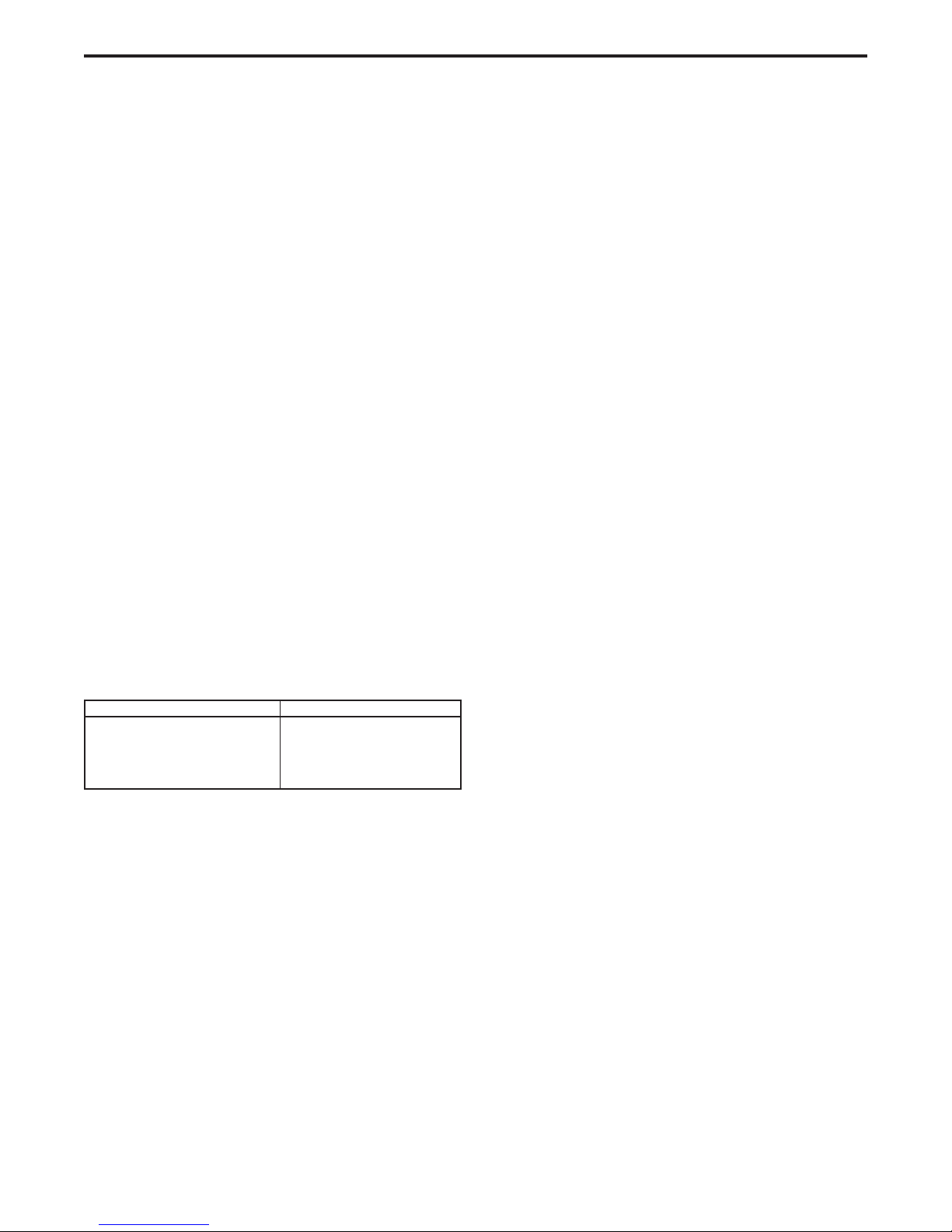
e. Set NA-3 open circuit voltage control to approxi-
mately the same setting as the weld setting. For
initial test welds, choose the voltage setting based
on the table below. Set the inch control to 2.
These are approximate settings only until the weld-
ing procedure has been set.
It should be noted that with the DC-1500 the OCV
required for optimum starting is lower than that
required with other type power sources.
f. Run a test weld, setting the proper current, voltage
and travel speed.
g. Once the proper welding procedure is established
and if the start is poor — wire blast-off, stub, etc.,
adjust the OCV and inch speed for optimum start-
ing. In general, a low inch speed will provide the
best starting.
Adjust the OCV by making repeated starts and ob-
serving the voltmeter action.
With proper adjustment of the OCV control, the
voltmeter needle will swing smoothly up to the de-
sired arc voltage and thus provide repeatable starts.
If the voltmeter swings above then back to the de-
sired welding voltage, the OCV setting is too high.
This usually results in a bad start where the wire
tends to “blast-off”.
If the voltmeter needle hesitates before coming up
to the desired voltage, the OCV is set too low. This
will cause the electrode to stub.
h. For Twinarc welding, clipping both wires to equal
lengths will be beneficial to make consistently good
starts.
3. Single Innershield Wire — Procedures and techniques
are the same as above, except starting is generally better
“hot” than “cold”. For electrical stickouts above 13/4an
NA-3 start board is required.
4. Twinarc Innershield — Procedures and techniques are
the same as above, except starting is generally better
“hot than “cold”. Use of an NA-3 start board improves
starting.
5. Twinarc Submerged Arc 1/16 — Procedures and tech-
niques are the same as above, except starting is best when
using CV Innershield and the NA-3 start board.
6. Use of the NA-3 Start Board — For those processes
above that recommend use of the NA-3 start board, the
following method should be used to set up the procedure.
a. Set start time at 0 and start current and voltage at
mid-range. Start the weld and set the proper current
and voltage for the welding procedure.
b. Turn the start board timer to maximum.
c. Set start board current 1 to 11/2dial numbers below
NA-3 front control settings.
d. Place start board’s voltage control approximately
equal to NA-3 voltage control setting.
When set per c and d, above, the starting only pro-
cedure will provide a current setting lower than the
NA-3 current setting and a voltage setting nearly
equal to the desired welding procedure.
e. With the start board time delay set at maximum,
establish the correct arc striking procedure as de-
scribed previously by changing OCV and inch speed.
f. Now increase the start board current and voltage to
bring the start current and voltage closer to the weld-
ing procedure. The start board current and voltage
should be as close to the welding procedure as pos-
sible while still getting satisfactory starts.
g. Now decrease the start time as low as possible for
optimum starts.
7. Arc striking with the DC-1500 mode switch in VV.
a. NA-3 — The NA-3 variable voltage board mode
switch should be set to the VV position.
b. Set OCV control at 6.5 to 7.0.
c. Other techniques recommended in the previous sec-
tions for good arc striking apply here also.
Approximate Voltage Voltage Control Setting
22-24 2
34-36 4
46-48 6
56-60 8
-8-