Page Number - 2
CENTRO-MATIC®
Form 403168
Table of Contents
Safety................................................................................................2
Controller Operation......................................................................2
Description......................................................................................2
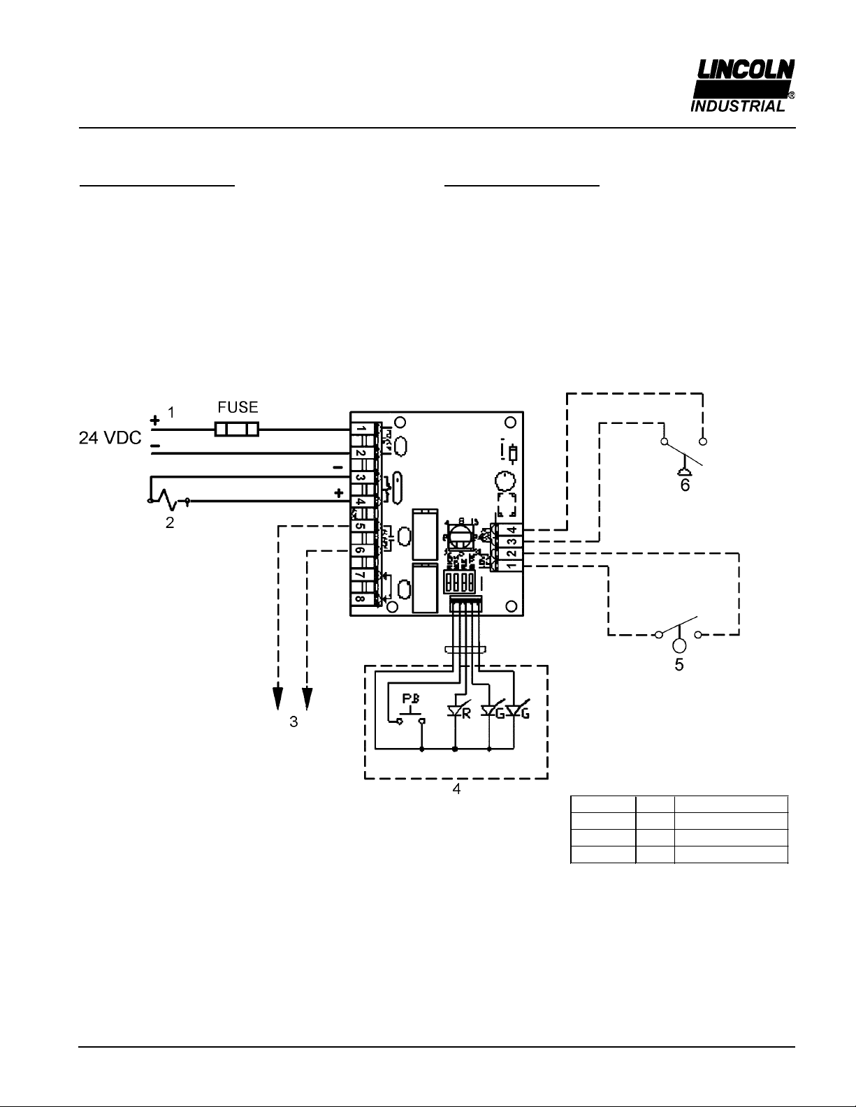
Field Connections..........................................................................3
Wiring Diagram..............................................................................3
Contoller Components and Setting the Controller....................4
Repair Parts List........................................................................4
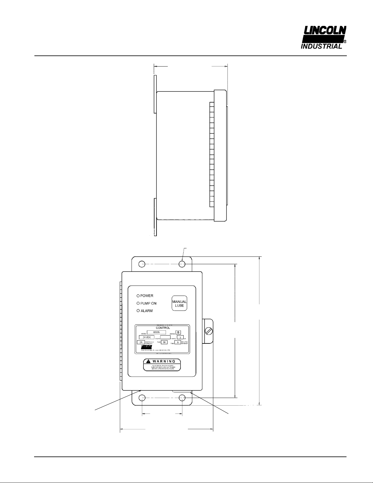
Dimensions....................................................................................
Troubleshooting....................................................................6
Safety
Read and carefully observe these operating instructions
before unpacking and operating the controller! The
controller must be operated, maintained and repaired
exclusively by persons familiar with the operating
instructions. Local safety regulations regarding installation,
operation and maintenance must be followed.
Operate this controller only after safety instructions and this
service manual are fully understood.
This symbol identifies
the potential for a
hazardous situation.
If this warning is not
followed, a serious
injury could occur.
Description
General Description
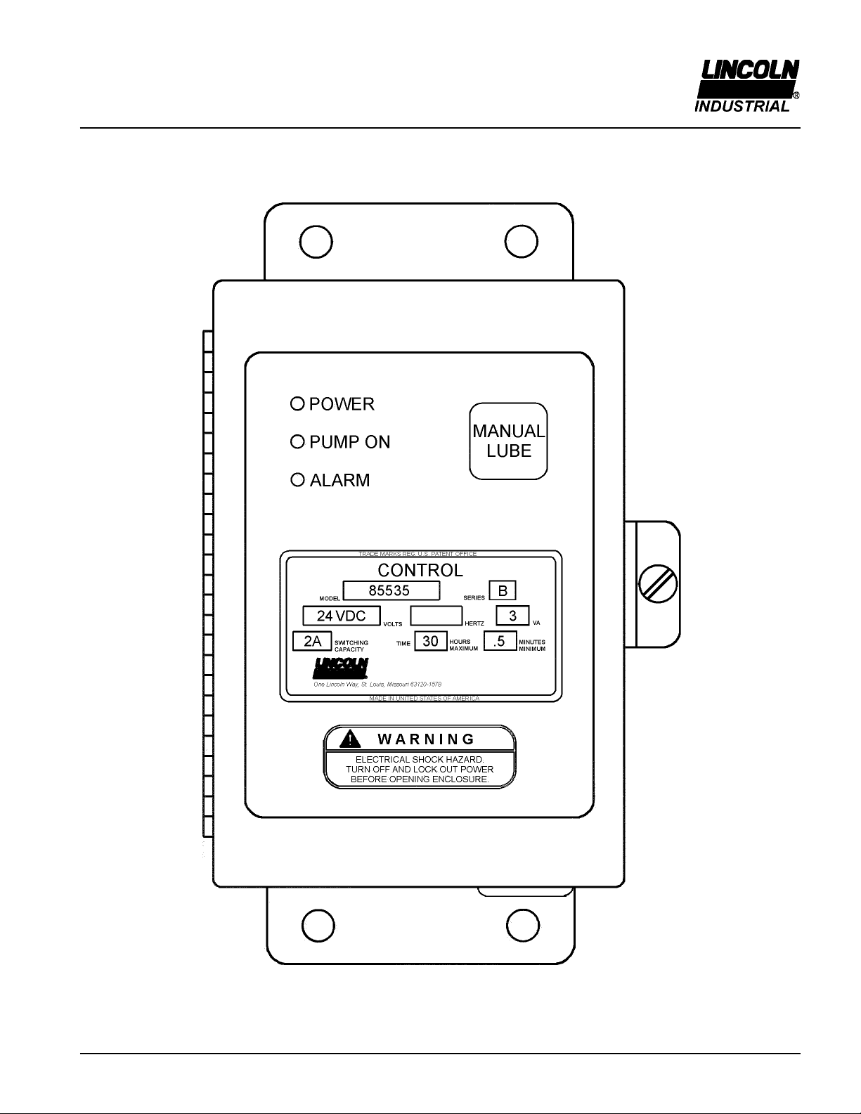
Model 8 3 controller is used to program the cycle
frequency of a lubrication pump. Lube cycles are
determined by the setting of internal switches. The cycles
times are selected to meet system requirements. During
the ON time, the air to the pump solenoid will be
energized.
Appropriate Use
Model 8 3 is exclusively designed for use in a
Centralized Lubrication System.
The maximum ratings given should not be exceeded.
Any other use not in accordance with the instructions will
result in loss of claim for warranty and liability.
Product Specification:
Input Voltage: 21 VDC to 30 VDC
Current Consumption: 100 MA (less external load)
Load Relay Contact: 2 amps inductive load at 30 VDC
Alarm Relay Contact: 2 amps inductive load at 30 VDC
Enclosure: NEMA 12
Temperature Range: -40° F to 1 0° F (-40° C to 6 ° C)
Net Weight: 4 lbs.
O Time (adjustable): 30 seconds minimum
30 hours maximum
On Time: 30 seconds minimum
2 minutes maximum
Lubrication System: Centro Matic
Controller Operation
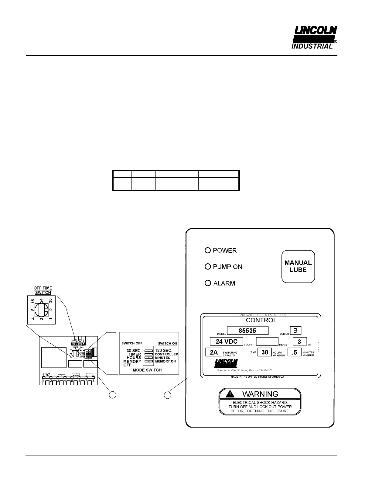
The time between lube events is determined by the setting
of the rotary switch, which selects the numeral setting, and
the dipswitch, which selects the units in either minutes or
hours.
When used in the timer mode, the pump will remain on for
the amount of time that was selected by the dipswitch. Time
will be either 30 seconds or 2 minutes (see Timer Mode).
When used in the controller mode, the amount of time that
the pump is on is determined by the closing of a pressure
switch in the lube supply line (see Controller Mode). Failure
of the pressure switch to close within the time setting of the
dipswitch, either 30 seconds or 2 minutes, will result in an
alarm condition. The alarm LED will turn on and the alarm
contact will close. The controller will continue to initiate lube
cycles while in alarm.
When the low-level switch closes, the alarm LED will turn on
and the alarm contact will close. The controller will continue
to initate lube cycles while in alarm. Alarm condition will
remain until low-level switch opens.
Pressing the manual lube button on the enclosure cover will
always initiate a lube event.
The memory feature will work as follows:
Dipswitch set to Memory Off Will result in a lube cycle
each time power is turned on. Lube cycle will start at the
beginning of the on time setting.
Dipswitch set to Memory On
1. Power is turned off during the off time (time between
lube cycles). When turning power back on will cause the
lube cycle to continue from the point of interruption.
2. Power is turned off during the on time or pumping time.
Turning power back on will cause the lube cycle to start
at the beginning of the on time setting.
Timer Mode
When the dipswitch is set to the timer mode, amount of
time that the pump is on will be determined by the setting of
the dipswitch. Time will be either 30 seconds or 2 minutes.
Controller Mode
When the dipswitch is set to the controller mode, a
pressure switch must be installed in the lube supply line.
This will provide pressure-monitoring capabilities. The
pressure switch will reset the controller when the set
pressure is detected. The controller will initiate an alarm
when the pump fails to develop sufficient pressure to
actuate the pressure switch within the dipswitch setting of
30 seconds or 2 minutes.