EWIKON motion CONTROL SD User manual

Controller for electric valve gate systems
with single linear servo drives
Operating manual
valid for item numbers:
68152.202
68152.204
68152.208
from software version 1.00.0
EWIKON 01/2022

2 2022_01_Operating manual_motion CONTROL SD_EN.indd

32022_01_Operating manual_motion CONTROL SD_EN.indd
Content
1. General information ................................................................................................................................................. 6
1.1 Information on this operating manual ........................................................................................................................ 6
1.2 Manufacturer .............................................................................................................................................................. 6
1.3 Formal information on this operating manual ............................................................................................................ 6
1.4 Conventions ............................................................................................................................................................... 7
1.4.1 Instructions and system responses ........................................................................................................................... 7
1.4.2 Enumerations ............................................................................................................................................................. 7
1.4.3 Abbreviations ............................................................................................................................................................. 7
2. Safety instructions .................................................................................................................................................. 8
2.1 Safety instructions and symbols used ....................................................................................................................... 8
2.1.1 Signalwordsforhazardclassication........................................................................................................................ 9
2.1.2 Explanation of pictograms ......................................................................................................................................... 9
2.2 Intended use ............................................................................................................................................................ 10
2.3 Improper use ............................................................................................................................................................ 10
2.4 Qualicationofsta ................................................................................................................................................. 10
2.4.1 Requirementsonspecialisedsta........................................................................................................................... 10
2.5 Personal Protective Equipment (PPE) ..................................................................................................................... 10
2.5.1 Symbols of the personal protective equipment ........................................................................................................ 10
2.6 Hazards and safety measures in connection with hot runner systems .................................................................... 11
2.7 Electrical equipment ................................................................................................................................................ 13
2.8 Spare and wear parts, auxiliary material ................................................................................................................. 13
2.9 Limitation of liability .................................................................................................................................................. 13
2.10 Warranty terms ........................................................................................................................................................ 14
2.11 Standards and directives ......................................................................................................................................... 14
3. Technical Data ........................................................................................................................................................ 15
3.1 Mechanical data ....................................................................................................................................................... 15
3.1.1 Main dimensions / Dimensions of the motion CONTROL SD controller ................................................................ 15
3.2 Electrical data .......................................................................................................................................................... 15
3.2.1 Connections / Connector pin assignment ................................................................................................................ 15
3.3 Operating conditions ................................................................................................................................................ 15
3.4 Placing the controller ............................................................................................................................................... 16
4. Functional description of the motion CONTROL SD controller ............................................................................ 17
4.1 Required accessories (connection cables) .............................................................................................................. 17
4.2 Function ................................................................................................................................................................... 17
5. Operating instructions .......................................................................................................................................... 18

4 2022_01_Operating manual_motion CONTROL SD_EN.indd
5.1 Safety instructions ................................................................................................................................................... 18
5.2 Operating requirements ........................................................................................................................................... 19
5.2.1 Technical requirements ............................................................................................................................................ 19
6. Assembly ................................................................................................................................................................ 20
6.1 Safety instructions ................................................................................................................................................... 20
6.2 Checks before installation ........................................................................................................................................ 20
6.3 Installation ................................................................................................................................................................ 22
6.3.1 Connections and connector assignment of a 4-zone controller ............................................................................... 22
6.3.2 Connecting the motion CONTROL SD controller to the injection moulding machine ............................................. 23
6.3.3 Connecting the motion CONTROL SD controller to the mould .............................................................................. 25
6.4 Checks after assembly ............................................................................................................................................ 25
7. Start up ................................................................................................................................................................... 26
7.1 Basic settings and operation .................................................................................................................................... 26
7.2 Description of the menus ......................................................................................................................................... 27
7.2.1 Start page ................................................................................................................................................................ 27
7.2.2 Screen layout ........................................................................................................................................................... 28
7.2.3 Operation ................................................................................................................................................................. 30
7.2.3.1 Manual operation ..................................................................................................................................................... 30
7.2.3.2 Automatic operation ................................................................................................................................................. 31
7.2.3.3 Error messages of the servo controller .................................................................................................................... 32
7.2.4 Congurationofdrives............................................................................................................................................. 33
7.2.4.1 General (basic settings) ........................................................................................................................................... 33
7.2.4.2 Motion(Motionprolesetting) ................................................................................................................................. 34
7.2.4.3 Monitoring ................................................................................................................................................................ 35
7.2.4.4 Options (Optional settings) ...................................................................................................................................... 36
7.2.4.5 Extended (Extended settings) .................................................................................................................................. 36
7.2.5 Setup System & Device ........................................................................................................................................... 37
7.2.5.1 General .................................................................................................................................................................... 37
7.2.5.2 Display & View ......................................................................................................................................................... 38
7.2.5.3 Network .................................................................................................................................................................... 39
7.2.5.4 Analog IN ................................................................................................................................................................. 39
7.2.5.5 OPC UA Id ............................................................................................................................................................... 40
7.2.6 Diagnosis and troubleshooting ................................................................................................................................ 41
7.2.6.1 Alarms ...................................................................................................................................................................... 41
7.2.6.2 Alarm history ............................................................................................................................................................ 41
7.2.6.3 I/O Test .................................................................................................................................................................... 42
7.2.6.4 System Diagnostics Manager (SDM) ....................................................................................................................... 42
7.2.7 File management ..................................................................................................................................................... 43

52022_01_Operating manual_motion CONTROL SD_EN.indd
7.2.7.1 Internal ..................................................................................................................................................................... 43
7.2.7.2 External USB ........................................................................................................................................................... 43
7.2.7.3 Report ...................................................................................................................................................................... 44
7.3 Help in case of malfunctions .................................................................................................................................... 45
7.3.1 Troubleshooting ....................................................................................................................................................... 45
7.3.2 Spare parts list ......................................................................................................................................................... 45
7.3.3 EWIKON service departments ................................................................................................................................. 45
8. Quick Start Guide .................................................................................................................................................. 46
9. Service and maintenance ...................................................................................................................................... 47
9.1 Maintenance instructions ......................................................................................................................................... 47
9.2 Safety instructions for maintenance ......................................................................................................................... 47
9.3 Maintenance work .................................................................................................................................................... 48
9.3.1 Changingthelter.................................................................................................................................................... 48
9.3.2 Cleaning the motion CONTROL SD controller ....................................................................................................... 48
9.3.3 Checking fan or fan grille ......................................................................................................................................... 48
9.4 Service and repair instructions ................................................................................................................................ 48
10. Decommissioning .................................................................................................................................................. 49
10.1 Returning the motion CONTROL SD controller ...................................................................................................... 49
10.2 Safety instructions for dismantling ........................................................................................................................... 49
10.3 Disposal instructions ................................................................................................................................................ 49
EC - Declaration of Conformity ........................................................................................................................................... 51

6 2022_01_Operating manual_motion CONTROL SD_EN.indd
1. General information
1.1 Information on this operating manual
Theseoperatingmanualhasbeenpreparedinaccordancewithdirective2006/42/EC.Itenablesthesafeandecient
operation of motion CONTROL SD controllers.
1.2 Manufacturer
EWIKON Heißkanalsysteme GmbH
Siegener Straße 35
35066 Frankenberg
Phone: +49 6451 501-0
Fax: +49 6451 501-202
Web: www.ewikon.com
1.3 Formal information on this operating manual
Person in charge of documentation: Horst Balzer
Version: 1.0, date: 23/06/2022
Language: German (original operating manual); English
© Copyright, 2022
All rights reserved. Full or partial reproduction subject to prior written
approval by EWIKON Heißkanalsysteme GmbH
NOTE!
Improper operation of the device may result in severe personal injury and considerable material damage!
You must carefully read this operating manual and familiarise yourself with the safety installations before
installing, commissioning or maintaining the device. Do not operate the device without having received
appropriate training.

72022_01_Operating manual_motion CONTROL SD_EN.indd
1.4 Conventions
1.4.1 Instructions and system responses
Operating steps that have to be carried out by the operator are displayed as a numbered list.
The sequence of the steps has to be adhered to.
Example:
1. Operating step 1
2. Operating step 2
1.4.2 Enumerations
Enumerations without mandatory sequence are displayed as a list with bullet points.
Example:
• Point 1
• Point 2
1.4.3 Abbreviations
The following terms and abbreviations are used in the operating manual:
Abbreviation Meaning
PPE Personal protective equipment
PE Protective earth conductor
EU European Union
Chart 1: Terms and abbreviations

8 2022_01_Operating manual_motion CONTROL SD_EN.indd
2. Safety instructions
The motion CONTROL SD controller complies with the Low Voltage Directive 2014/35/EU and the EMC Directive
2014/30/EU and has been designed, manufactured and tested for safety in accordance with the currently applicable safety
regulations and laws and the state of the art. If the motion CONTROL SDcontrollerisusedinamannernotspeciedby
EWIKON, the function of the protective devices of the device may be impaired.
The motion CONTROL SD controller is delivered in perfect technical condition.
However, hazards can arise from motion CONTROL SD controllers if they are:
• operated by personnel who have not been properly trained.
• used improperly or not as intended.
• not in perfect condition from a safety point of view.
2.1 Safety instructions and symbols used
The safety instructions are introduced with signal words and are marked by symbols. They draw attention to dangerous
situations that may arise during installation, operation and maintenance work. Safety instructions must be observed to avoid
accidents, personal injury and damage to material.
Warnings
• protect against possible personal injury and damage to material if observed.
• classify the extent of the hazard by means of the signal word.
• indicate the danger of personal injury by means of the hazard sign.
• indicate the type and source of the hazard.
• indicate the risk and the possible consequences.
• indicate measures to avoid hazards and prohibit certain types of behaviour.
WARNING! = Signal word
Source of hazard
Possible consequences, if ignored
• Measures / prohibitions
The hazard sign marks warnings which warn against personal injuries.
Source of hazard
The source of hazard indicates the cause of hazard.
Possible consequences, if ignored
If the warnings are ignored, possible consequences will be e. g. crushing, burnings or other severe injuries.
Measures / Prohibitions
“Measures / Prohibitions” lists actions that are to be carried out to prevent a hazard (e. g. stop a drive) or that are
prohibited in order to prevent a hazard.

92022_01_Operating manual_motion CONTROL SD_EN.indd
2.1.1 Signal words for hazard classication
HAZARD
Indicates an imminently hazardous situation which, if not avoided, will result in death or serious injury.
WARNING!
Indicates a potentially hazardous situation which, if not avoided, will result in death or serious injury.
CAUTION
Indicates a potentially hazardous situation which, if not avoided, will result in minor injury or material damage.
NOTE
Indicates useful additional information and tips to promote trouble-free operation and to prevent material
damage.
2.1.2 Explanation of pictograms
Read operating manual Caution! Risk of electrocution
Caution! Hot surface Caution! Oxidising agents
Caution! Suspended load Caution! Risk of hand injuries / crushing
Caution! Explosive atmosphere Caution! Risk of hand and cut injuries
Caution! Systems under pressure Caution!Movingforklifttrachazard

10 2022_01_Operating manual_motion CONTROL SD_EN.indd
2.2 Intended use
EWIKON controllers are designed exclusively for the intended use described here.
Any other use contrary to the intended use is excluded and may lead to personal injury and damage to material. In this case,
the warranty expires.
The motion CONTROL SD controller is to be used exclusively for controlling the valve pin movement of EWIKON valve gate
hot and cold runner systems installed in a closed injection mould.
Intended use requires that all notes and information in these operating manual are read, understood and observed.
To ensure safe operation of the motion CONTROL SDcontroller,thespeciedmaintenanceandinspectionintervalsmust
be observed.
Use of the motion CONTROL SD controller
Only use the motion CONTROL SD controller for its intended purpose and in perfect condition in terms of
safety! This is the only way to ensure the operational safety of the motion CONTROL SD controller.
2.3 Improper use
Anyusenotspeciedunderorgoingbeyondtheintendeduseisconsideredimproperuse.
2.4 Qualication of sta
Thestamusthavetheappropriatequalicationsforassembly,maintenanceandrepair.
Anylackofknowledgeonthepartofthestamustbeeliminatedthroughtrainingandinstruction.
2.4.1 Requirements on specialised sta
Improper use of EWIKON controllers can lead to personal injury and damage to material. All work must be carried out by
specialisedstaonly.
OnlytrainedspecialisedstaisallowedtoconnectandoperateEWIKONcontrollers.Specialisedstahastechnicaltraining,
proven knowledge and experience in handling e.g. injection moulding equipment or electrical systems, as well as knowledge
of the relevant safety regulations and is able to independently recognise possible dangers and avoid them by taking suitable
protective measures.
2.5 Personal Protective Equipment (PPE)
Wear the necessary protective equipment when working on or near the machine. Special instructions for personal protective
equipment in the working area must be observed.
2.5.1 Symbols of the personal protective equipment
Always wear the following when carrying out any work:
Protective clothes:Toprotectyourbodyweartight-ttingclotheswithlowresistancetotearing,without
protruding parts and with long sleeves and long trousers. Do not wear rings, chains or any other jewelry.
Safety shoes: To protect yourself against electric shocks, melt splashes, heavy, falling objects and slips
and falls on slippery surfaces.

112022_01_Operating manual_motion CONTROL SD_EN.indd
Always wear the following when carrying out special work:
Safety glasses: To protect your eyes
against scattering debris, heat and melt
splashes.
Ear protection: To protect your ears
against loud ambient noises.
Face mask: To protect your face against
scattering debris, heat and melt splashes. Protective helmet: To protect your head
against falling objects and sharp edges.
Protective gloves (heat resistant):
To protect your hands against extreme
heat, abrasions, punctures and more
severe injuries.
Heat resistant apron: To protect your
body against extreme heat.
2.6 Hazards and safety measures in connection with hot runner systems
In principle, the operator of the system is subject to the legal obligations for occupational safety. In addition to the safe-
ty instructions in this manual, the safety, accident prevention and environmental protection regulations applicable to the
system‘sareaofusemustbeobserved.Theoperatormustclearlydeneresponsibilitiesandensurethatallstaoperating
the system has read and understood these instructions. Information about hazards must be provided regularly. Protective
equipmentmustbeprovidedforthesta.Maintenanceintervalsmustbeobserved.
Risk of physical injuries by high pressure or unexpected material leakage
• Unexpected material leakage may result in burns. There is a risk of serious injuries or death and/or
damage to the hot runner.
• There is also a risk of burns, if water gets onto or into the hot runner. If the water reaches dangerous-
ly high temperatures, the metal housing may burst and cause serious injuries due to emerging water
vapour or melting resins.
Safety measures
• Make sure the hot runner system heats up evenly. Particularly for large manifolds it may be necessa-
ry to switch on nozzle and sprue bush heaters at the same time, but later than the manifold heaters.
• Makesurethenozzletipsand/orthegatesarenotblockedbysolidiedresinthathasahighermel-
ting point and that there is no humidity on the hot runner system, e.g. caused by a leaky temperature
control circuit.
Risk of burns
• Hot surfaces
Many components of the hot runner systems get very hot and may cause severe skin burns when
being touched.
• Hot material (plastic melt)
Never touch material leaking from the nozzle/the mould/the hot runner or the material inlet. Even
material that seems to be cooled down already may still be hot inside the core and cause burns.
Safety measures
• Please make sure you wear your personal protective equipment (PPE) when working near or on a
hot runner system. Pay special attention to warnings indicating hot surfaces. All components have
to be cooled down to ambient temperature before you start working. Exceptions to these rules are
explicitly mentioned.

12 2022_01_Operating manual_motion CONTROL SD_EN.indd
Risk of electric shocks
• Danger to life by electric shock.
Touching live surfaces may result in severe or even lethal injuries.
• Always keep water away from live components and the hot runner. There is a risk of short circuits!
Safety measures
• Electrical systems have to be disconnected from the mains and secured against being switched on
again before any work is carried out. Only authorised electricians are allowed to carry out any work
on electrical systems.
• All components have to be connected to a suitable power source according to the wiring diagrams
and in compliance with the applicable local regulations. Injection moulding machine and hot runner
systems have to be grounded.
Risk of physical injuries by suspended / heavy load
• Onlytrainedstaisauthorisedtooperateliftingdevicesandforklifttrucks.Proceedslowlyandwith
care. Prevent uncontrolled swinging of the load (e. g. the manifold).
Safety measures
• Lifting devices and forklift trucks have to be designed in such a way that they bear the weight and the
size of the hot runner system/manifold. Make sure YOU use the marked lifting points.
Risk of physical injuries by pressurized connecting lines (compressed air, hydraulic oil, water etc.)
• All supply lines to the hot runner and/or the hot runner system or the hot half have to be long enough
topreventanystresswhenthemouldhalvespart.Theymustnotbeaectedbymovingpartsofthe
mould or of the machine. Prevent the hoses from rubbing over the edges of the mould as they may
be damaged because this will create the risk of a spontaneous leakage of pressurized process media
(pressurised air, hydraulic oil, water).
Safety measures
• Make sure you have depressurized all supply lines before carrying out any work. Only skilled person-
nel is allowed to carry out work on the supply lines. Please wear your personal protective equipment
(PPE).
Risk of physical injuries by sharp edges and corners
• Sharp edges and corners pose a risk of injury, possibly resulting in skin abrasions and cut injuries.
Safety measures
• Make sure you wear protective gloves when working near sharp edges and corners. Proceed with care.
• Make sure the system is clean and free of burrs!
Risk of physical injury by crushing of extremities
• There is risk of injury when lifting heavy loads during assembly. Your hands or other parts of the body
may be crushed.
Safety measures
• Make sure you wear protective gloves to prevent injuries while working close to heavy loads.
• Keep all parts of your body away from danger areas while setting down heavy loads during assem-
bly.

132022_01_Operating manual_motion CONTROL SD_EN.indd
2.7 Electrical equipment
HAZARD!
Residual voltage after activation
Risk of death by electric shock and severe injuries caused by live components.
• Check for zero potential before performing any work!
Anyworkonelectricalequipmentmustbecarriedoutbyqualiedelectricians.Alwaysapplythe5safetyruleswhenworking
with electrical components:
• Disconnect from the mains
• Secure against reconnection (by activating the repair switch and installing a safety lock at the same time, if necessary)
• Verify that the installation is dead
• Carry out grounding and short circuiting
• Provide protection against adjacent live parts
Maintenanceworkmustbecarriedoutbyqualiedandtrainedstaormaintenancestainaccordancewith
DIN EN 61010-2-201. Never use the motion CONTROL SD controller with faulty or inoperable electrical connections.
Incaseofenergysupplydisruptionsimmediatelyswitchothemotion CONTROL SD controller. The maintenance & in-
spection schedules regarding electrical components given by the manufacturers have to be adhered to. Check for damaged
insulation at regular intervals.
2.8 Spare and wear parts, auxiliary material
The use of non-OEM spare and wear parts as well as auxiliary material may pose risks. Only use original parts or parts
approved by EWIKON Heißkanalsysteme GmbH.
2.9 Limitation of liability
All information and instructions given in this manual have been compiled in consideration of the applicable standards and
regulations, state of the art as well as our know-how and experience.
EWIKON does not assume liability for any damage caused by:
• Non-observance of this manual
• Improper use
• Useofunskilledsta
• Unauthorisedretrottingortechnicalmodications
• Use of non-approved spare parts
The technical service provided verbally, in writing or on the basis of tests represents our best knowledge but is not binding
and does not release you from carrying out additional tests on the products supplied by us regarding their suitability for the
intended use.
The use of the products is beyond our control. Therefore, it is your own responsibility to ensure that the products meet your
specicrequirements.Nevertheless,shouldanissueofliabilityarise,alldamageshallbelimitedtothevalueoftheproducts
supplied by EWIKON and used by you.
We guarantee the perfect quality of our products in accordance with our general terms and conditions of sale and payment
as well as the extended warranty conditions.
These are available on our homepage www.ewikon.com.
The statutory provisions prevailing at the time of conclusion of the contract shall apply.
We reserve the right to make technical changes within the scope of improving the properties of use and further development.

14 2022_01_Operating manual_motion CONTROL SD_EN.indd
2.10 Warranty terms
For warranty conditions of hot runner systems and components please refer to the terms and conditions of EWIKON.
2.11 Standards and directives
EWIKON hot runner systems conform to the following European directives:
• Machinery Directive 2006/42/EC
• Low Voltage Directive 2014/35/EU
• EN ISO 12100:2010 Safety of machinery -
General principles for design - Risk assessment and risk reduction
• EN 60204-1:2018 Safety of machinery -
Electrical equipment of machines - Part 1: General requirements
EWIKON controllers conform to the following European directives:
• Low Voltage Directive 2014/35/EU
• EMC Directive 2014/30/EU
• EN61010-1: 2020-03 Safety requirements for electrical equipment for measurement, control, and laboratory use -
part 1: General requirements
• EN61010-21201: 2019-04 (draft standard) Safety requirements for electrical equipment for (draft standard)
measurement, control and laboratory use - part 2-201: Particular requirements for control equipment

152022_01_Operating manual_motion CONTROL SD_EN.indd
3. Technical Data
3.1 Mechanical data
3.1.1 Main dimensions / Dimensions of the motion CONTROL SD controller
Size Description Qty. / size (approx.) Unit
2-zone controller
Item no. 68152.202 Dimensions (H x B x T) 190 x 355 x 400 mm
Weight approx. 9,5 kg
4-zone controller
Item no. 68152.204 Dimensions (H x B x T) 190 x 355 x 400 mm
Weight approx. 9,9 kg
8-zone controller
Item no. 68152.208 Dimensions (H x B x T) 460 x 220 x 550 mm
Weight approx. 21 kg
Chart 2: Main dimensions / Dimensions of the motion CONTROL SD controller
3.2 Electrical data
3.2.1 Connections / Connector pin assignment
Description Qty. / size (approx.) Unit
Voltage AC (+10 % / -15 %) 230 V
Frequency 50/60 Hz
Power max. 540
2-zone / 4-zone controller W
max. 1020
8-zone controller
Protection class IP20
Chart 3: Electrical data
3.3 Operating conditions
Operating conditions Size (approx.) Unit
Ambient temperature (operation) +5 to +40 °C
Ambient temperature (storage) -40 to +70 °C
Relative humidity for operation (up to 31 °C) max. 80
(linearly decreasing to
max. 50 % at 40 °C)
%
Pollution degree 2
Chart 4: Operating conditions

16 2022_01_Operating manual_motion CONTROL SD_EN.indd
3.4 Placing the controller
Placethecontrolleronastable,at,non-combustibleworkingsurface.Thedisplayshouldbeateyelevelwiththeuserto
facilitate reading of the display and operation of the device.
Thedeviceincludesabuilt-infanontherearsideaswellasventilationslotsontheunderside,protectedbyalter.Make
surethattheairowthroughtheseopeningsisnotobstructed.
Keep a minimum distance of 0.2 m in all directions around the device to other equipment and parts of buildings.
0.2 m
0.2 m
0.2 m

172022_01_Operating manual_motion CONTROL SD_EN.indd
4. Functional description of the motion CONTROL SD controller
4.1 Versions of the motion CONTROL SD controller
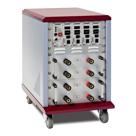
Picture 1: 2- or 4-zone controller (item no. 68152.202/204)
4.2 Required accessories (connection cables)
Qty Item no. Description Remark
1 60070.050-V06 Signal cable M23, 17-pin, Pin, 6 m 1 pc per controller
1 63050.130(-V06) Hybrid motor cable SpeedTec 4G0, 75 mm2, 3 m (6 m) 1 pc per drive
Chart 5: Connecting cables required for the motion CONTROL SD controller (not included in delivery!)
4.3 Function
The motion CONTROL SD controller enables precise control of the opening and closing movement for electric valve gate
systems, especially for sequential gating. Depending on the version, two, four or eight drives can be connected to one
motion CONTROL SDcontroller.Onlylinearactuators(servomotorswithintegratedspindle)qualiedbyEWIKONcanbe
used as drives.
Application range of the motion CONTROL SD controller
This EWIKON control system can be used to operate electrically operated valve gate systems from EWIKON
Heißkanalsysteme GmbH in dry rooms in the industrial sector.

18 2022_01_Operating manual_motion CONTROL SD_EN.indd
5. Operating instructions
5.1 Safety instructions
WARNING!
Residual voltage after activation
Risk of electric shock due to live parts and risk of severe injuries due to moving parts
• Ensure zero potential before performing any work on or inside the motion CONTROL SD controller
• Set the power switch to OFF and disconnect the mains plug
• Wait for 5 minutes until the condensers for the DC link voltage are discharged.
• Connection,repairandmaintenanceworkmayonlybecarriedoutbyqualiedspecialisedsta!
Checks and protective measures before startup
The connected drives and hot runner components can get hot
There is crush hazard due to moving parts (e. g. pistons, cylinders)
• The installation must be checked in accordance with EN 60204-1 or recognised standards of good practice
before starting up the valve gate system.
• Appropriate precautions must be taken for startup and operation.

192022_01_Operating manual_motion CONTROL SD_EN.indd
DANGER!
Insucient protective conductor connection to injection moulding machine
Fatal electric shock or serious injuries due to live components.
• When starting up the system the operator has to make sure that all electrically operated system compo-
nents are connected to the protective conductor system of the injection moulding machine or are safeguar-
ded by equivalent safety measures before he applies any electric voltage.
• Before switching on a drive system it has to be made sure that the housing is properly connected to ground
potential (PE bar). The earth connections must be installed, even if the drive system is connected only for
testing purposes or for a short period!
5.2 Operating requirements
5.2.1 Technical requirements
An input signal for „release“ sent from the injection moulding machine or the hotrunner controller is necessary to prevent the
system from being operated when it is cold or when the safety door is open.
At least one trigger signal from the injection moulding machine is required to control the drive(s). It triggers the stroke mo-
vement of the drive via the control unit. The „start injection“ signal is preferably used to open the valve pins, alternatively the
„start build-up of clamping force“ or „close mould“ signal can be used. Closing of the valve pins usually takes place at „end of
holding pressure“.
When a signal is applied (+24 V), the drive moves and causes the valve pins to open and to remain in this position. When
the signal is cancelled (0 V), the valve pins close again. If the trigger signal is not made available by the controls of the in-
jection moulding machine as described, an adjustment will have to be made. Further digital or analogue signals can be used
toobtaine.g.complexmotionproles.
The motion CONTROL SD controllers are exclusively designed for the drives mentioned below.
Item no. Description Selection
22902 Drive for valve pin Ø 2,0 mm, stroke = 10 mm SRV31-22900 ESM5522903 Drive for valve pin Ø 3,0 mm, stroke = 10 mm
22904 Drive for valve pin Ø 4,0 mm, stroke = 15 mm
Chart 6: Drives that can be used with the motion CONTROL SD controller

20 2022_01_Operating manual_motion CONTROL SD_EN.indd
6. Assembly
Thepurposeofthefollowingnotesistosupporttheassemblystaduringtheassemblyofthemotion CONTROL SD
controller.Additionally,theassemblystahastohavetheknowledgerequiredtoconnectamotion CONTROL SD
controller.
6.1 Safety instructions
WARNING! PPE
Cut injuries due to sharp edges and risk of getting jammed
Cut injuries to body and extremities, mainly to the hands
Jammingofngersorhand
• Wear your PPE and take care.
Control of live components before installation
Physical injuries such as an electric shock.
• TheelectricalequipmentofthemotionCONTROLSDcontrollershouldbechecked,
especially those areas which will no longer be accessible after installation.
• Please check if cables are kinked or squeezed and if cable insulations are
undamaged.
Connected voltage supply during assembly
Risk of electric shock due to live parts
• The motion CONTROL SD controller and all connected components have to be
disconnected from the voltage source during installation.
6.2 Checks before installation
The motion CONTROL SD controller is subject to comprehensive testing by the manufacturer before delivery. For safety
reasons (transport or storage damage or damage to the device when preparing installation) we recommend that you check
the motion CONTROL SD controller for damage just before installing it.
This manual suits for next models
3
Table of contents
Other EWIKON Controllers manuals
