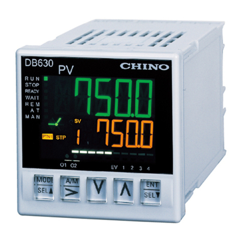
Chino DB600 Series User manual

J1
INST.No.DB6-61-6
デジタル指示調節計
DB600
取扱説明書 設置編
このたびは当社製品をお買いあげいただきまことにありがとうございます。
この製品を正しく安全にお使いいただくために、この取扱説明書を必ずお読
みになり、理解したうえでお使いください。本書は、いつもお手元においてご
使用ください。ご注文・ご使用に際しては、下記 URL より「ご注文・ご使用に
際してのご承諾事項」を必ずお読みください。
https://www.chino.co.jp/support/guarantee/index.html
この取扱説明書は、本製品をお使いになる担当者のお手元に確実に届くよう
にお取りはからいください。
この取扱説明書の全部、または一部を無断で複写、または転載することを禁
じます。この取扱説明書の内容を将来予告なしに変更することがあります。
この取扱説明書の内容については、万全を期しておりますが、万一ご不審な
点や記入もれなどがありましたら、当社までお申し出ください。お客様が運用
された結果につきましては、責任を負いかねる場合がございますので、
ご了承ください。
本書は使用上の注意事項と取り付け・結線・入力種類・パラメータ一覧・
主な仕様などを説明したものです。なお、本書以外の取扱説明書は
当社ホームページ https://www.chino.co.jp/ から会員登録をして頂き、
ダウンロードをお願いします。詳しい取り扱い方法などは、DB600「総合編」
または DB60Z「総合編」をご覧ください。
お買い上げいただいた DB600 は次のものが同梱されています。
取付具 2個(一式)パネル取り付け用
取扱説明書設置編(本書) 1部
本器前面には、表面保護のため保護膜が貼ってあります。取り付け・結線工
事が終わりましたら、保護膜をはがしてご使用ください。
当社が規定しない使い方をした場合、この製品に盛り込まれた安全保護は損
なわれます。
警告
取り扱いを誤った場合に、使用者が死亡または重傷を
負う危険の状態が生じることが想定される場合。
注意
取り扱いを誤った場合に、使用者が軽傷を負うか、ま
たは物的損害のみが発生する危険の状態が生じるこ
とが想定される場合。
警告
・電源を供給する前に、結線が正しいか、電源電圧が定格電圧に合って
いるかなどについて確認してください。
・本製品には、電源スイッチがありません。本製品に供給する電源には、
定格仕様に合ったサーキットブレイカを設置してください。
・本製品の端子部には、感電防止のため、最終製品側で使用者が直接
触れられない安全処置を施してご使用ください。
・本製品は一般工業製品向けの汎用品として設計しています。原子力・
放射線関連機器、医療機器、航空宇宙機器、鉄道や舶用の輸送用機な
ど人命及び財産にかかわる用途での使用は意図していません。人命及
び財産にかかわる高い品質・安全性を要求される設備に使用される場合
には、お客様の責任において、保護・安全回路の設計及び設置を行っ
て安全性の確保をお願いします。
・本製品の内部に手や工具などを入れないでください。感電や怪我を
する恐れがあります。
・異臭、異音、煙などが発生したり、異常に高温になっている場合など
は、たいへん危険ですので、直ちに電源を遮断し、ご購入先、もしくは
最寄りの弊社営業所までご連絡ください。
・修理や改造が必要な場合は、ご購入先、もしくは最寄りの弊社営業所
までご連絡ください。弊社の認定したサービス員以外による部品交換な
どの修理や改造は禁止されています。
・本製品を正しく安全にご使用していただくため、本取扱説明書に従って
ご使用ください。誤使用により生じた傷害や損害、免失利益などいかなる
請求についても、弊社では一切その責任を負いかねますので、あらかじ
めご了承ください。
設置から最低限の初期設定までのフローを示します。
············ J2 ページ
············ J3 ページ
············ J5 ページ
手順 3入力種類の設定
手順 4SV の設定
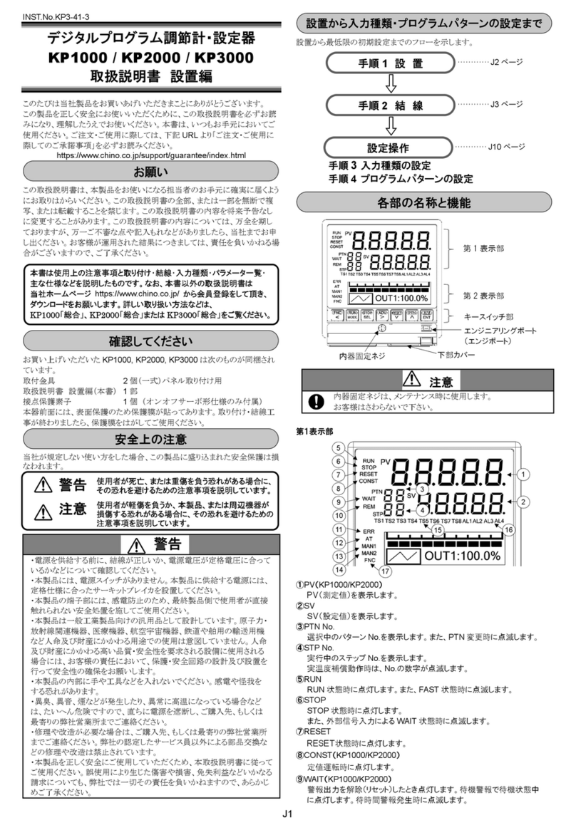
①測定値(PV)/パラメータ設定タイトル
測定値(PV)やパラメータ設定画面のタイトルを表示します
②設定値(SV)/運転状態/パラメータ設定値
設定値(SV)や各設定項目のパラメータ設定値を表示します
③設定パラメータ用カーソル
パラメータ設定画面表示中に桁切替が可能なパラメータの場合は[>]
キー押下で、カーソルが表示されます
④アナログバー
バー表示の設定により、測定値やパラメータのアナログバーを表示しま
す
⑤出力
出力状態を表示します
⑥イベント
イベント 1~4 の状態を表示します
⑦運転状態表示
各運転状態を表示します
⑧設定値の勾配表示
設定値(SV)の勾配状況を表示します
⑨パターン No.(プログラム運転 ON)※プログラム機能付き仕様
実行中または設定中のパターン No.が点灯します
⑩実行 No./ステップ No./グループ No./イベント No.
実行中または設定中の実行 No./グループ No. /イベント No.が点灯
します
⑪運転画面表示
運転画面の『PV/SV』表示中は SV が点灯、『PV/OUT1』表示中は
OUT が点灯、『PV/OUT2』表示中は OUT2 が点灯します。※OUT2 は
2 出力付き仕様
⑫通信ステータス表示 ※通信インターフェイス付き仕様
・通信表示(MODEa)が ON のとき
通信コマンドの送信中に S が点滅し、受信中に R が点滅します
※エンジニアリングポートの通信状態は表示しません。
■設置条件
本器を取り付けるときは、次のような所に設置してください。
(環境)
屋内
直射日光が当たらないところ
高温にならないところ
振動や衝撃がないところ
液体(水など)がかからないところ
結露しないところ
工業環境 (過電圧カテゴリ:Ⅱ、過渡過電圧:2500V、汚染度:2)
お願い
確認してください
安全上の注意
設置から入力種類の設定・SV の設定まで
手
順
1
設
置
手
順
2
結
線
設定操作
各部の名称と機能
手順 1 設 置
11
10
11
4
2
3
1
612
7
4
3
11
2
1
612
5
9
10
8
7
1
2
6
3
4
12
5
7
9
8
10
5
9
8
J2
(雰囲気)
強力なノイズ、静電気、電界、磁界がないところ
周囲温度-10~50℃以内(密着計装時は 40℃以内)、周囲湿度 20~
90%rh 以内のところ
温度変化が少ないところ
腐食性ガス、爆発性ガス、引火性ガス、可燃性ガスがないところ
塩分、鉄分、導電性物質(カーボン、鉄など)がないところ
蒸気、油、薬品がないところ
ちりやほこりがないところ
周囲に高発熱するものがないところ
熱がこもらないところ(本製品の内部温度上昇を防ぐため、通風スペース
を確保してください。ただし、端子部には直接風があたらないようにして
ください。風があたると指示が安定しない原因になります。)
製品の上部が広い空間であるところ
画面が見えやすいところ(本製品は、LCD 使用しているため、上下左右
斜めから見ると表示が見えにくくなります。) なるべく正面から表示部を
見られる所に設置してください。
LCD は長時間同じ画面を表示し続けると焼き付き(常時点灯など)が生
じる場合があります。長時間連続運転(基準動作条件で 3ヶ月以上)を
する場合は焼き付きを防ぐ為、定期的に別の画面を表示したり電源を
OFF してください。
電源端子およびリレー出力端子を除く入出力端子のコモンモード電圧
は最大で、30V r.m.s.以下、42.4V ピーク以下、DC60V 以下としてくだ
さい。
■取付条件
設置高度は、標高 2000m 以下
取付姿勢は、前後±10°以下、左右±10°以下
■その他
本製品を有機溶剤(アルコールなど)で拭かないでください。
本製品の誤動作防止のため、本製品の近くで携帯電話は使用しないで
ください。
本製品の近くのテレビやラジオなどに障害を与える場合がありますことを
ご了承ください。
■外形寸法
●DB63 (単位:mm)
●DB65
●DB67
■パネル取り付け寸法 (単位:mm)
●DB63
パネルカット 密着計装時
●DB65
●DB67
■パネル取り付け方法
1 取付溝を確認します
2
パネルに組み込みます
3
本製品を固定します
■シンボルマーク
製品本体や本取扱説明書に、下記のシンボルマークがございますので、そ
れらの意味について、充分にご理解ください。
ラベル 名称 意味
アラートシンボルマーク 感電や怪我などの恐れがあるために、取扱
説明書を参照する必要がある箇所です。
交流 交流を示します。
直流/交流 直流/交流両用を示します。
外郭保護 二重絶縁または強化絶縁で全体が保護さ
れている機器を示します。
警告
感電の恐れがあるため、パネルへの取り付けや結線作業時は、
必ず電源を OFF にしてください。
手順 2 結 線
()
()
()

J3
結線上の注意
◆結線作業は専門業者が行う
結線作業は、電気関係の基礎知識を持ち、実務経験がある方が行ってく
ださい。
◆端子カバーをつける
安全性確保のため、結線終了後、製品の端子に直接触れられないような
処置を施してください。
本製品専用の端子カバーはアクセサリで用意しております(別売)。
◆強電回路及び、ノイズ発生源から離す
ノイズによる悪影響防止のため、ノイズ発生源(マグネットリレー、モータ、サ
イリスタレギュレータ、インバータなど)となる機器の近辺に設置しないでく
ださい。また、本製品の配線とそれらからの配線を同一ダクト内に通すこと
なども避け、必ず離して配線してください。必要に応じて、ノイズ対策を施し
てください。
◆測定値への影響について
上記のノイズ及び高電圧などで測定値に影響している恐れがある場合は、
ほかの測定方法などで測定値が正常かどうかを確認してください。また必
要により対策を施してください。
◆発熱源から離す
高温による悪影響防止のため、発熱源の近辺に設置しないでください。発
熱源が近辺にあると、測定誤差が生じたり、最終的には、製品の寿命を著
しく縮める原因にもなります。製品の周囲温度にご注意ください。また、風
が直接あたるところや急激な周囲温度変化が起こった場合なども測定誤差
が生じますので、そのような周囲環境を避ける処置も施してください。
◆未使用端子
未使用端子は、何も接続しないでください。製品の故障となる場合がありま
す。
◆電源 ON 時の誤出力対策
電源 ON 時、本製品が正常に起動するまでの間、出力関係の信号が瞬時
的に出力される場合があります。
必要に応じて、外部回路にて対策を施してください。
◆本器に接続する機器または装置について
本器に接続する機器または装置は、本器の電源、入出力部の最高使用電
圧に適した強化絶縁が施されたものを使用してください。
■絶縁ブロック
●DB63
電源端子
測定入力端子
リモート入力端子 R
/
L(アナログ)DI 端子
調節出力 1端子
(電流出力形
/
SSR 駆動パルス出力形
/
電圧出力形)
調節出力 1端子(オンオフパルス出力形)
イベント出力 1
/
2(メカリレー出力)端子
通信端子 R
/
L(デジタル)DI 端子
外部信号入力(DI1~5)端子
※「24V AC/DC」の場合、電源端子は 2次側になります。
※調節出力 1(オンオフパルス出力形)、イベント出力 1
/
2(メカリレー出力)の間は、
絶縁されています。
●DB65/67
電源端子
測定入力端子 CT 入力端子
リモート入力端子 R
/
L(アナログ)DI 端子
外部信号入力(DI6
/
7)端子
調節出力 1
/
2端子
(電流出力形
/
SSR 駆動パルス出力形
/
電圧出力形)
オンオフサーボ(フィードバック入力)端子
伝送出力端子(4-20mA DC
/
0-10V DC)
調節出力 1
/
2端子(オンオフパルス出力形)
イベント出力 1~4(メカリレー出力)端子
オンオフサーボ(リレー出力)端子
通信端子 R
/
L(デジタル)DI 端子
外部信号入力(DI1~5)端子
イベント出力 5~9(オープンコレクタ出力)端子
※「24V AC/DC」の場合、電源端子は 2次側になります。
※調節出力 1
/
2(オンオフパルス出力形)、イベント出力 1~4(メカリレー出力)の間
は、絶縁されています。
■結線の基本
端子への接続、電源端子については総合取扱説明書 2-3-4 結線の基本を
参照してください。
■結線
●DB63
①調節出力 1+
⑩R
/
L(デジタル) DI4
②調節出力 1-
⑪DI1 DI5
③測定入力+
⑫R
/
L & DI COM DI COM
④測定入力+ A
⑬EV1
⑤測定入力- B
⑭EV1 COM
⑥測定入力 b
⑮EV2
⑦通信 SA DI1 ⑯EV2 COM
⑧通信 SB DI2 ⑰電源 L
/
+
⑨通信 SG DI3 ⑱電源 N
/
-
調節出力 1端子 通信/外部信号入力
オンオフパルス出力 RS-485 + 外部信号入力 1点
電流/SSR 駆動パルス/
電圧出力
外部信号入力 5点
測定入力端子※1※2
熱電対/電圧 mv
電圧 V(電流)
イベント出力端子(メカリレー出力)
測温抵抗体
イベント 1出力
電源端子
イベント 2出力
100-240V AC 電源
※1 指定端子以外には、結線しな
いでください。
※2 電流を入力する場合、受信
抵抗(250Ω/別売品 EZ-
RX250)を+、-間に接続します。
24V AC/DC 電源
4
-20mA DC
SSR駆動パルス(12V)
0-10V DC

J4
●DB65 ●DB67
①測定入力 +⑦調節出力 2 +EV1
②測定入力 +A ⑧調節出力 2 -EV1 COM
③測定入力 -B ⑨EV2
④測定入力 b ⑩EV2 COM
⑤調節出力 1 +⑪電源 L/+
⑥調節出力 1 -⑫電源 N/-
⑬通信 RDA SA
⑭通信 RDB SB
⑮通信 SDA
⑯通信 SDB
⑰通信 SG SG
⑱R
/L(デジタル)DI
⑲DI1 EV5
⑳DI2 EV6
DI3 EV7
DI4 EV8
DI5 EV9
R
/L & DI COM R/L & EV COM
EV3 (サーボ M3)※3
EV3 COM (サーボ M2)※3
EV4 (サーボ M1)※3
EV4 COM (サーボ R1)※3
伝送出力 +(サーボ RC)※3
伝送出力 -(サーボ R2)※3
リモート入力 +(伝送出力+)※3
リモート入力 -(伝送出力-)※3
R
/L(アナログ)DI (リモート入力+)※3
CT DI6 (リモート入力-)※3
CT DI7 (R/L(アナログ)DI)※3
R
/L & DI COM (R/L COM)※3
サーボ M3※4
サーボ M2※4
サーボ M1※4
サーボ R1※4
サーボ RC※4
サーボ R2※4
※3 ()内は DB65 の場合
※4 DB67 の場合
調節出力 1端子 通信/外部信号入力/イベント出
力端子(オープンコレクタ出力)
オンオフパルス出力 RS-422A + 外部信号入力 5点
電流/SSR 駆動パルス/
電圧出力
オンオフサーボ出力※5
RS-485 + 外部信号入力 5点
測定入力端子※6※7
熱電対/電圧 mv
電圧 V(電流)
RS-422A + イベント出力 5点
測温抵抗体
電源端子
100-240V AC 電源
24V AC/DC 電源
※5 図はDB65 の場合です。
DB67 の場合は端子番号 37 番以
降となります。
※6 指定端子以外には、
結線しないでください。
※7 電流を入力する場合、受信
抵抗(250Ω/別売品 EZ-
RX250)を+、-間に接続します。
4
-20mA DC
SSR駆動パルス(12V)
0-10V DC
電源

J5
RS-485 + 外部信号入力 5点
調節出力 2/
イベント出力端子
(メカリレー出力)
オンオフパルス出力
※DB67 のみ
電流/電圧出力
イベント 1出力 外部信号入力 5点
イベント出力端子
(メカリレー出力)
イベント 2出力 イベント出力 5点
伝送信号出力/イベント出
力端子(メカリレー出力)
4-20mA/0-10V
リモート信号入力/外部信号入力
/ヒータ断線警報用
CT 入力端子
4-20mA/0-10V
+ イベント出力 2点4-20mA/0-10V
イベント出力 2点外部信号入力 2点
4-20mA/0-10V
+ 外部信号入力 2点
(オンオフサーボ出力形の
場合)
伝送信号出力
4-20mA/0-10V
リモート信号入力
4-20mA/0-10V 4-20mA/0-10V
+ CT 入力※9
伝送信号出力
+ リモート信号入力
4-20mA/0-10V
CT 入力※9
※8 リモート信号入力用の R/L(Analog)切替信号は、個別スイッチや
リレー出力などの独立接点をご使用ください。子器が複数の場合、
異なる機器の R/L(Analog)DI COM 間同士を接続すると子器のリ
モート SV 値に指示誤差が生じて正常動作しなくなります。子器が
1台の場合、トランジスタ出力接点を接続することが可能です。
(詳細は総合編の 2-3-5 結線例を参照してください。)
※9 指定カレントトランス(CT):株式会社 U-RD 社製「CTL-6-S-H」
次ページのキー操作と表示の遷移を参考に、設定を行ってください。
手順 3 入力種類の設定例(測定レンジ表参照)
運転画面にて キーを 1秒以上押し、MODE0 初期設定画面を表示しま
す。 キーを押し、MODE5 を表示させ キーを押し、
(入力種類)を表示させます。 キーで入力種類を選択します。
キーを押して設定内容を登録します。
手順 4 SV の設定例
(定値運転の場合)運転画面にて キーを 1秒以上押すと、MODE0 初
期設定画面を表示します。MODE0 が表示されたら、 キーを押します。
画面が表示されたら、 キーで桁の移動や値の増減をし
てください。 キーで登録します。
(プログラム運転の場合)運転画面にて キーを 1秒以上押すと、
MODE0 初期設定画面を表示します。 キーを押し、MODE2 を表
示させ、 キーを押します。プログラムパラメータを設定します。
設定操作
※8
※8
※8
※8
※8

J6
パラメータディレクトリ一覧表
■運転画面 ■パラメータ設定画面(MODE0~MODEt)
○形式コード、オプションの有無によっては表示されない項目があります。

J7
熱電対 測定範囲 測定精度
□□□
□ B 0.0~1820.0℃
±0.1% of FS±1digit
0℃未満は
±0.2% of FS±1digit
400℃未満 :規定外
400~800℃:±0.2%FS±1digit
□□□
□ R 0.0~1760.0℃400℃未満 :±0.2%FS±1digit
□□□
□ S 0.0~1760.0℃
□□□
□ N 0.0~1300.0℃
□□□
K -200.0~1370.0℃
□□□
K -200.0~500.0℃
□□□
□ E -200.0~900.0℃
□□□
□ J -200.0~1200.0℃
□□□
□ T -200.0~400.0℃
□□□
□ U -200.0~400.0℃
□□□
□ L -200.0~900.0℃
C(WRe5-WRe26) 0.0~2310.0℃
W-WRe26 0.0~2310.0℃400℃未満 :±0.4%FS±1digit
PlatinelⅡ0.0~1390.0℃
□
PtRh40-PtRh20 0.0~1880.0℃±0.3% of FS±1digit 400℃未満 :規定外
400~800℃:±0.8%FS±1digit
Au-Pt 0.0~1000.0℃±0.3% of FS±1digit
直流電圧 測定範囲
□
±20mV -20.00~20.00mV
±0.1% of FS±1digit
±100mV -100.0~100.0mV
□□
□
±5V -5.000~5.000V
□
□
±10V -10.000~10.000V
測温抵抗体 測定範囲
□
□
Pt100 -200.0~850.0℃
±0.1% of FS±1digit
□
□
Pt100 -200.0~200.0℃
□
JPt100 -200.0~649.0℃
□
JPt100 -200.0~200.0℃
□
Pt50 -200.0~649.0℃
※直流電流 4~20mA を入力する場合、受信抵抗 250Ω(別売)を外付けしてください。※精度は、基準動作条件における性能です。
※熱電対は、上記の測定精度に基準点補償精度が加算されます。
●DB63
形 式
制御
アルゴリズム 調節出力 1 調節出力 2 通信・
入出力 プログラム機能
警報イベント
出力2点 付加機能 電源電圧 仕 様
DB63
48×48 サイズ
1
PID制御
2
Z制御
1
オンオフパルス出力形
3
電流出力形
5
SSR 駆動パルス出力形
6
電圧出力形
0
なし
0
なし
S
RS-485+外部信号入力 1 点[DI1]
D
外部信号入力 5 点[DI1~5]
― なし
P
プログラム機能あり
0
なし
1
警報イベント出力 2 点[EV1,2]※1
0 なし
※1 警報イベントはメカリレー出力のみで機能するため、イベント機能を確認して選択 OP 付加の場合、コード表を参照※2
してください。 A 100-240V AC
※2 以下の OP 付加の場合、「付加機能」桁に下表コードを選択してください。 D 24V AC/DC
コード 防水仕様 出力スケーリング 下限バーンアウト 開平演算
1 ● - - -
A※3 - ● - -
B - - ● -
C - - - ●
E※3 ● ● - -
F ● - ● -
G ● - - ●
※3 PID 制御のみ指定可。
測定レンジ表
形式コード
●:OP 付加

J8
●DB65/67
形 式
制御
アルゴリズム
調節出力
1
調節出力
2
通信・
入出力
伝送・警報
イベント出力
リモート・
外部信号入力
プログラム
機能
警報イベント
出力2点
付加
機能
電源
電圧 仕 様
DB65
48×96 サイズ
DB67
96×96 サイズ
1
PID制御
2
Z制御
1
オンオフパルス出力形
2
オンオフサーボ出力形
3
電流出力形
5
SSR 駆動パルス出力形※7
6
電圧出力形
0
なし
1
オンオフパルス出力形※1※10
3
電流出力形※1※7
6
電圧出力形※1※7
0
なし
A
RS-422A+外部信号入力 5 点[DI1~5]
S
RS-485+外部信号入力 5 点[DI1~5]
B
RS-422A+状態イベント出力 5 点[EV5~9]※6
C
RS-485+状態イベント出力 5 点[EV5~9]※6
0
なし
4
4-20mA+警報イベント出力 2 点[EV3,4](※1)※6
6
0-10V+警報イベント出力 2 点[EV3,4](※1)※6
7
警報イベント出力 2 点[EV3,4](※1)※6
0
なし
5
4-20mA
7
0-10V
8
4-20mA+外部信号入力 2 点[DI6,7](※2)※3
A
0-10V+外部信号入力 2 点[DI6,7](※2)※3
B
外部信号入力 2 点[DI6,7](※2)※3
※1 「調節出力 1」が「1」、「3」、「5」、「6」の場合に指定可。 ― なし
P
プログラム機能あり
※2 「調節出力 1」が「1」、「3」、「5」、「6」で、「警報イベント出力 2 点+ 0 なし
ヒータ断線検知」が「0」、「1」の場合に指定可。 1 警報イベント出力 2 点[EV1,2]※4※6※7
※3 「警報イベント出力 2 点+ヒータ断線検知」が「0」、「1」の場合に指定可。 2 警報イベント出力 2 点[EV1,2]
+ヒータ断線検知※4※5※6※7
※4 「調節出力 2」付きの場合、警報イベント出力の点数は 1 点[EV2]のみ。 0 なし
※5 ヒータ断線検知は、「調節出力 1」または「調節出力 2」が「1」、「5」で、 OP 付加の場合、コード表を参照※8
「リモート信号入力+外部信号入力 2 点」が「0」、「5」、「7」の場合に指定可。 A 100-240V AC
(DB67 のみ)「調節出力 1」と「調節出力 2」が共に「1」の場合、調節出力 1 で動作。 D 24V AC/DC
※6 警報イベントはメカリレー出力のみで機能するため、イベント機能を確認して選択してください。
※7 以下の形式を選択し、設定することにより、マルチ出力で使用することができます。
形式 調節出力 1 調節出力 2 警報イベント出力 2 点+ ヒータ断線検知
DB6□□53□□□□1□□ SSR 駆動パルス出力 電流出力 警報イベント出力[EV2]
DB6□□53□□□□2□□ SSR 駆動パルス出力 電流出力 警報イベント出力[EV2] + ヒータ断線検知
DB6□□56□□□□1□□ SSR 駆動パルス出力 電圧出力 警報イベント出力[EV2]
DB6□□56□□□□2□□ SSR 駆動パルス出力 電圧出力 警報イベント出力[EV2] + ヒータ断線検知
警報イベント出力[EV2]は、設定によりオンオフパルス出力として機能します。
※8 以下の OP 付加の場合、「付加機能」桁に下表コードを選択してください。
コード 防水仕様 出力
スケーリング
下限
バーンアウト 開平演算 オープンループ方式
オンオフサーボ仕様
1 ● - - - -
A※9 - ● - - -
B - - ● - -
C - - - ● -
D - - - - ●
E※9 ● ● - - -
F ● - ● - -
G ● - - ● -
H ● - - - ●
※9 PID 制御のみ指定可。
※10 DB67 のみ指定可。
()あり注記は DB65 の場合、()なし注記は DB67 の場合、太字の注記は DB65/DB67 共通です。
●:OP 付加

J9
清 掃 :本製品の前面、キーなどの清掃は、水を含ませ固く絞っ
た布でかるく拭いてください。LCD 表示部は、帯電防止
のため、乾いた布で拭かないでください。(LCD が帯電し
た場合は、数分で正常に戻ります。)有機溶剤(アルコー
ルなど)は使用しないでください。
オーバーホール
:長期的に信頼性を保つため、2~3年を目処にオー
バーホールをお勧めします。ご用命は、ご購入先、もしく
は最寄りの弊社営業所までご相談ください。
なお、本製品の明らかな寿命部品は下記の通りです。一般的にはほとんどの
部品について、経年変化や経年劣化が生じます。
部品名 推定寿命
リレー
※調節出力用、イベント出力用 約10 万回
電解コンデンサ
※電源回路の平滑用コンデンサ
約5年
(周囲温度:30℃、
運転時間 12 時間/日)
適正な設定や操作を行わなかった場合、下記のようなワーニング No.が
約3秒間表示されます。
ワーニング内容をご確認の上、再度、適正な設定や操作を行ってください。
ワーニング No. ワーニング内容
プログラム運転実行不可です。プログラムパターンが
正しく設定されているかご確認ください。
フィードバックチューニングの失敗、または、サーボ
のゼロ調整値が、スパン調整値を超えています。
フィードバック入力の結線で、OPEN 側と CLOSE
側が正しく結線されていることを確認してください。
□
キーロック中です。“キーロック(MODEt)”を『機能
OFF』に設定・変更してください。
通信書込中にパラメータ変更を行った場合、キー操
作を抑制する為、一時的にキーロック状態になって
います。キーでパラメータ変更を行う場合には、通信
書込を停止し、一度、[▼SEL]キーまたは[▲SEL]
キーで画面遷移を行ってください。
システムに異常が発生した場合、下記のようなエラーNo.が約 2秒間表示さ
れます。エラー内容をご確認の上、ご購入先、もしくは最寄りの弊社営業所ま
でご連絡ください。
エラーNo. エラー内容
PV/RJ のA/D変換異常
フィードバック/リモート信号入力の A/D変換異常
校正データ異常
エラー表示中、各機能は次の動作を行います。
項 目
(フィードバック
異常)
(リモート
異常)
測定値(PV)値の
更新停止
値の
更新停止
値の
更新停止 通常動作
フィードバック
測定値 通常動作 値の
更新停止 通常動作 通常動作
リモート SV 入力 通常動作 通常動作 値の
更新停止 通常動作
制御出力 通常動作 通常動作 通常動作 通常動作
イベント出力 通常動作 通常動作 通常動作 通常動作
伝送出力 通常動作 通常動作 通常動作 通常動作
通信 通常動作 通常動作 通常動作 通常動作
外部信号入力 通常動作 通常動作 通常動作 通常動作
OP:オプション
入力仕様
入力信号:
熱電対 B
、R、S、N、K、E、J、T、U、L、
C(WRe5-WRe26)、W-WRe26、
PlatinelⅡ、PtRh40-PtRh20、Au-Pt
直流電圧 ±20mV、±100mV、±5V、±10V
測温抵抗体 Pt100、JPt100、Pt50
精度定格 測定レンジの±0.1% of FS±1digit
詳細は「測定レンジ表」を参照
基準点補償精度 ±1.0℃(周囲温度 23℃±10℃)
±2.0℃(上記以外の範囲)
許容入力電圧 熱電対 ±10V DC
直流電圧(
mV
)
±10V DC
直流電圧(
V
)
±20V DC
測温抵抗体 ±5V DC
調節仕様
制御周期 約0.1 秒
出力形式 オンオフパルス出力形、オンオフサーボ出力形
(DB650、DB670 のみ)、電流出力形、
SSR 駆動パルス出力形、電圧出力形
オンオフパルス出力形:
接点タイプ 1a 接点
パルス周期 約1~180 秒
接点容量 抵抗負荷 240V AC 3A, 30V DC 3A
誘導負荷 240V AC 1.5A, 30V DC 1.5A
最小負荷 5V DC 10mA
オンオフサーボ出力形:
接点タイプ 1a 接点
フィードバック抵抗 100Ω~2kΩ
接点容量
抵抗負荷 240V AC 3A, 30V DC 3A
誘導負荷 240V AC 1.5A, 30V DC 1.5A
最小負荷 5V DC 10mA
電流出力形:
出力仕様 4-20mA DC
負荷抵抗 600Ω以下
SSR 駆動パルス出力形:
パルス周期 約1~180 秒
出力仕様 オン時 12V DC±20%
(負荷電流は
21mA
以下)
オフ時 0.8V DC 以下
電圧出力形:
出力仕様 0-10V DC
出力抵抗 約10Ω
負荷抵抗 50kΩ以上
2出力付き仕様:
出力形式 オンオフパルス出力形、電流出力形、電圧出力
形で、任意組み合わせが可能。
絶縁 2
出力間は非絶縁(オンオフパルス出力形を除
く)
制御方式 PID 方式、スプリット方式
一般仕様
定格電源電圧 100-240V AC(±10%), 24V AC
/
DC(±10%)
定格電源周波数 50
/
60Hz(±2%)
最大消費電力:
100-240V AC 仕様(OP なし)
DB630 100V AC : 4VA, 240V AC : 5VA
DB650 100V AC : 4VA, 240V AC : 6VA
DB670 100V AC : 4.5VA, 240V AC : 7VA
100-240V AC 仕様(OP あり)
DB630 100V AC : 5VA, 240V AC : 7VA
DB650 100V AC : 7VA, 240V AC :10VA
DB670 100V AC : 9VA, 240V AC :12VA
24V AC
/
DC 仕様(OP なし)
DB630 24V AC : 3VA, 24V DC : 2W
DB650 24V AC : 4VA, 24V DC : 3W
DB670 24V AC : 4.5VA, 24V DC : 3.5W
24V AC
/
DC 仕様(OP あり)
DB630 24V AC : 4VA, 24V DC : 3W
DB650 24V AC : 7VA, 24V DC : 5W
DB670 24V AC : 8VA, 24V DC : 6W
外形寸法 DB630 48(W)×48(H)×88(D)
(パネル面からの奥行き寸法は 80)
DB650 48(W)×96(H)×73(D)
(パネル面からの奥行き寸法は 65)
DB670 96(W)×96(H)×73(D)
(パネル面からの奥行き寸法は 65)
保 守
ワーニング表示
エラー表示
仕 様

J10
質量 DB630
(OP なし)約 120g, (OP あり)約 135g
DB650
(OP なし)
約150g, (OP あり)約 230g
DB670
(OP なし)
約240g, (OP あり)約 330g
端子ネジ M3.0
正常動作条件
周囲温度 -10~50℃(密着計装時:-10~40℃)
最大周囲湿度(周囲温度-10~31℃の場合) 90%r h(結露しないこと)
最大周囲湿度(周囲温度 31~50℃の場合)90~50%r h(結露しないこ
と)※31℃のときは 90%r h から、50℃のときは 50%r h へリニアに減少
最小周囲湿度 20%r h
電源電圧:
100-240V AC
仕様
90~264V AC
24V AC
/
DC 仕様 21.6~26.4V AC
/
DC
電源周波数 50
/
60Hz±2%
取付姿勢 前後±10°、左右±10°
設置高度 標高 2000m 以下
振動 0 m/s
2
衝撃 0 m/s
2
取付条件 パネル取付(上下空間)
外部ノイズ なし
周囲温度変化率 10℃
/
hour 以下
輸送条件
周囲温度 -20~60℃
周囲湿度 5
~95%r h(結露しないこと)
振動 4.9 m/s
2
以下(10~60Hz)
衝撃 392 m/s
2
以下(出荷時梱包状態)
対応規格
EMC 指令 EN61326-1
適合(CE、UKCA)ClassA
※試験中、最大±10%、または±2mV
のいずれか大きい方に相当する指示値
や出力値が変動することがあります。
安全 EN61010-1 適合(CE、UKCA)
EN61010-2-030 適合(CE、UKCA)
UL61010-1 認証(UL)
UL61010-2-030 認証(UL)
CAN/CSA C22.2 No.61010-1 認証(cUL)
過電圧カテゴリ:Ⅱ
汚染度:2
環境規制 RoHS(CE、UKCA)
環境規制規格:EN IEC63000 適合
(産業用を含む監視および制御機器)
File No. E214646 (UL)
イベント出力(OP)
出力点数 メカリレー DB630:最大 2点DB650:最大 4点
DB670:最大 4点
オープンコレクタ
最大 5点
出力容量(メカリレー出力):
接点容量 抵抗負荷 240V AC 3A, 30V DC 3A
誘導負荷 240V AC 1.5A, 30V DC 1.5A
最小負荷 5V DC 10mA
出力容量(オープンコレクタ出力):
出力容量 24V DC 50mA
ヒータ断線検知(OP)
機能 外付けカレントトランス(CT)を使用して、ヒータ電流
を測定し、断線を検知する機能
入力点数 1
点
CT 入力レンジ 0.0-65.0mA AC(50/60Hz)
ヒータ電流測定範囲 5.0-50.0A AC
測定カテゴリー なし
入力信号 5.0-50.0A(50
/
60Hz)
精度 ±5.0% of FS±1digit
※指定カレントトランス(CT):株式会社 U-RD 社製「CTL-6-S-H」
別売品 LTA-P207(800 ターン、穴径 5.8mm)
伝送信号出力(OP)
出力点数 1
点
出力信号 4-20mA DC
(負荷抵抗 400Ω以下)
0-10V DC
(負荷抵抗 50kΩ以上)
精度 ±0.3% of FS
出力更新周期 約0.1 秒
絶縁 調節出力 1
/
2とは非絶縁(オンオフパルス出力
形を除く)
リモート信号入力(OP)
入力点数 1
点
入力信号 4-20mA DC
(入力抵抗 約 50Ω)
0-10V DC
(入力抵抗 約 100kΩ)
最大許容入力 直流電流 ±30mA 以下
±1.5V DC 以下
直流電圧 ±20V DC 以下
精度 ±0.3% of FS±1digit
取込周期 約0.1 秒
外部信号切替 R
/
L(リモート
/
ローカル)
外部信号入力(OP)
入力点数 DB630
最大 5点 COM 共通
DB650
最大 7点 COM 共通
DB670
最大 7点 COM 共通
入力信号 無電圧接点
外部接点容量 5V DC 2mA
機能 定値運転 RUN
/
READY 切替、AUTO
/
MAN 切
替、プリセットマニュアル、タイマー1、タイマー2、
警報イベントリセット、実行 No.選択、プログラム
/
定値運転切替、プログラム運転 RUN
/
STOP 切
替、プログラム運転 ADVANCE、プログラム運転
RESET、プログラムパターン選択
通信インターフェイス(OP)
種類 DB630 RS-485
DB650/670 RS-422A、RS-485
プロトコル Modbus-RTU、Modbus-ASCII、Private(デジタ
ル伝送
/
デジタルリモート入力で使用)
機能 上位通信
/
デジタル伝送
/
デジタルリモート入力
形式コード、オプションの有無によっては表示されない項目があります
項 目 範 囲 初期値
運
転
画
面
PV(測定値)
to
[℃]
:オーバーレンジ
:アンダーレンジ
SV(設定値)
to
[℃] □□
□
ステップ時間
to
[時:分] □
□
第1出力値
to
[%]
第2出力値
to
[%]
AUTO
/
マニュアル切替
□:AUTO 出力
:マニュアル出力
□
イベントステータス
:全イベント OFF □to
:全イベント ON
:警報イベントリセット
タイマー
1
経過時間
表示
to
[秒] □□□
□
タイマー
2
経過時間
表示
to
[秒] □□□
□
CT 測定値表示
to
[A]
:測定値未取得 □
□
FB 測定値表示
to
[%]□□
□
PID
オートチューニング
□□:
チューニング未実行/強制終了
:
第
1
出力用
PID
チューニング開始
:
第
2
出力用
PID
チューニング開始
:
チューニングステップ
1□to
:
チューニングステップ
4
□
□
FB チューニング
□□:
チューニング
未実行/強制終了
:FB
チューニング
開始
□
□
:ゼロ
側の
FB
チューニング
□
□
:
スパン側の
FB
チューニング
パターンリピート残回数
表示
to
[回] □□□
□
RUN
/
READY
切替
□□:RUN 状態
:READY 状態
□
□
定値運転用実行
No.
選択
to
□
□
パターン No.選択
to
□
□
プログラム駆動
:
プログラム運転
RESET
□□:
プログラム運転
RUN
□:
プログラム運転
STOP
□□:
プログラム運転
ADVANCE
□□:
プログラム運転
END
電子機器の廃棄について
本製品はWEEE指令適用製品です。
製品の廃棄については、再利用、リサイクルのため、
適切な分別回収をお願いします。
DB600 パラメータ一覧表

J11
項 目 範 囲 初期値
M
O
D
E
0
実行中
SV
to
[℃] □□
□
実行中
ステップ時間
to
[時:分] □
□
実行中
イベント 1、3
to
実行中
イベント 2、4
to
実行中
P
:二位置制御
to
[%]□□
□
実行中
I
to
[秒] □□
□
実行中
D
to
[秒] □□
□
実行中出力リミッタ
L
to
[%]□□
□
実行中出力リミッタ
H
□
to
[%]
□
実行中
実温度補償
:機能 OFF
to
[℃] □□
□
M
O
D
E
1
SV 変化率上昇
:機能 OFF
to
[℃] □□
□
SV 変化率下降
:機能 OFF
to
[℃] □□
□
SV 変化率単位
□:秒、
□:分、
:時 □
□
定値運転用
PV スタート
:SV スタート(PV スタート OFF)
:PV スタート
□□
□
READY 時
警報動作
:
READY
状態の警報イベントの演算なし
□:
READY
状態の警報イベントの演算あり
□
□
M
O
D
E
2
プログラム
/
定値運転切替
:
定値運転(プログラム運転
OFF
)
□:
プログラム運転
(プログラム運転
ON
)
□□
□
プログラム運転用
時間単位
:[時:分]
:[分:秒]
□□
□
RESET 時SV
to
[℃] □□
□
パターンリピート
to
[回] □□□
□
運転画面の
時間表示
□:ステップ経過時間
:ステップ残時間
□
パターンクリア
□:パターンクリアなし
:パターン No.1 の初期化□to
:パターン No.4 の初期化
□:全パターンの初期化
□
□
パターンコピー
□:
パターンコピーなし
:
パターン
No.1
を
No.2
にコピー
to
:
パターン
No.4
を
No.3
にコピー
□
□
ステップ数
to
:ステップなし
to
:ステップ数 1 to 12
□□□
□
プログラム運転用
PV スタート
:
SV
スタート(
PV
スタート
OFF
)
:
PV
スタート
□□
□
開始 SV
to
[℃] □□
□
プログラム運転用
SV
to
[℃] □□
□
ステップ時間
to
[H:M, M:S]□
□
プログラム運転用
実行 No.選択
□:前回の No.を継続
□
to
□
□
(
STEP1
)
□
□
(
STEP1
以外)
END 時の
第1出力
:定値制御(AUTO 出力)
to
[%]
□
END 時の
第2出力
:定値制御(AUTO 出力)
to
[%]
□
リンク先のパターン
No.
:リンクなし
:パターン No.1□to
:パターン No.4
□
□
M
O
D
E
3
定値運転用
SV
to
[℃] □□
□
イベント 1、3
to
イベント 2、4
to
P
:二位置制御
to
[%]□□
□
I
to
[秒] □□
□
D
to
[秒] □□
□
出力リミッタ L
to
[%]□□
□
出力リミッタ H □
to
[%]
□
実温度補償
:機能 OFF
to
[℃]
□□
□
M
O
D
E
4
イベントモード
□□:イベントなし
□:絶対値上限警報
□:絶対値下限警報
□:偏差上限警報
□:偏差下限警報
□:絶対値偏差上限警報
□:絶対値偏差下限警報
□:設定値上限警報
□:設定値下限警報
□:出力値上限警報
□:出力値下限警報
□:ヒータ上限警報
□:ヒータ下限警報
:タイマー1警報
:タイマー2警報
□:FAIL 警報
□:定値運転のRUN 状態
:プリセットマニュアル状態
□□:リモート入力状態
□:SV 上昇状態
□
(
EV1
,
EV3
)
□
□
(
EV2
,
EV4
)
□
□
(
EV5 to EV9
)
□
項 目 範 囲 初期値
M
O
D
E
4
□:SV 下降状態
□:
プログラム運転の
ステップ切替状態
□
:
プログラム運転のステップ
1
状態
to
:
プログラム運転のステップ
12
状態
□:
プログラム運転の
RUN
状態
□:
プログラム運転の
STOP
状態
□□:
プログラム運転の
ADVANCE
状態
:
プログラム運転の
RESET
状態
□□:
プログラム運転の
END
状態
:
プログラム運転の
SV
保持状態
イベント拡張機能
□□:拡張機能なし
□:イベント待機
□:イベント保持
:イベント待機
/
保持
□
□
イベント不感帯
to
□
□
イベント出力位相
:通常位相の出力
:逆位相の出力
M
O
D
E
5
入力種類 測定レンジ表参照 □□
□
単位
:
℃(摂氏)
:mV
□:V
□□
□
測定範囲 L レンジ範囲内(※測定レンジ表参照)
測定範囲 H
リニア小数点
:小数点なし
:小数点 1桁□□to
:小数点 4桁
□
リニアスケール・ゼロ
to
□□
□
リニアスケール・スパン
to
センサ補正
to
[℃] □
□
デジタルフィルタ
to
[秒] □□
□
SV リミッタ L
to
[℃]
SV リミッタ H
to
[℃]
表示用小数点
:小数点なし
:小数点 1桁□□to
:小数点 4桁
□
M
O
D
E
6
パルス周期
to
[秒] □□
□
フィードバック・ゼロ
to
[%]□□
□
フィードバック・スパン
to
[%]
□
フィードバック不感帯
to
[%]□□
□
PID
不感帯
/
出力不感帯
to
[%]□□
□
調節動作
:加熱制御
:冷却制御
出力プリセット
to
[%]□
□
出力変化量
リミッタ
L
to
[%]
出力変化量
リミッタ
H
to
[%]
□
PV 異常時出力
to
[%]□□
□
プリセットマニュアル
to
[%]□□
□
電源 ON 時動作
:
READY
状態
/
プログラム運
転
RESE
T
:
前回電源
OFF
直前動作
制御アルゴリズム
:位置形 PID 制御
:速度形 PID 制御
:Z制御
または
フィードフォワード
:フィードフォワード演算なし
□:フィードフォワード演算あり
□
□
M
O
D
E
7
第
2
出力
制御方式
□□:PID 制御または Z制御
:スプリット制御
□
□
第
2
出力
P
:二位置制御
to
[%]
□□
□
第
2
出力
I
to
[秒] □□
□
第
2
出力
D
to
[秒] □□
□
第
2
出力
ギャップ
to
[%]□□
□
第
2
出力
PID
不感帯
/
出力不感帯
to
[%]□□
□
第
2
出力
調節動作
:加熱制御
:冷却制御
第
2
出力
出力プリセット
to
[%]□□
□
スプリット Direct
to
[%]□□
□
スプリット Reverse
to
[%]
□
第
2
出力パルス周期
to
[秒] □□
□
第
2
出力出力リミッタ
L
to
[%]□□
□
第
2
出力出力リミッタ
H
to
[%]
□
第
2
出力
変化量リミッタ
L
to
[%]
第
2
出力
変化量リミッタ
H
to
[%]
□
第
2
出力
プリセットマニュアル
to
[%]□□
□

J12
項 目 範 囲 初期値
M
O
D
E
a
通信プロトコル
□□:MODBUS RTU
:MODBUS ASCII
:Private
□
□
通信機能
□□:上位通信
:デジタル伝送
:
デジタルリモート入力
□
□
機器番号
to
□□□
□
通信伝送速度
□:4800bps
□:9600bps
:19200bps
:
38400b
p
s
□
通信キャラクタ
:7bit
/
偶数パリティ
/
ストップビット
1
:7bit
/
偶数パリティ
/
ストップビット
2
:7bit
/
奇数パリティ
/
ストップビット
1
:7bit
/
奇数パリティ
/
ストップビット
2
□
□
:8bit
/
パリティなし
/
ストップビット
1
:8bit
/
パリティなし
/
ストップビット
2
:8bit
/
偶数パリティ
/
ストップビット
1
:8bit
/
偶数パリティ
/
ストップビット
2
:8bit
/
奇数パリティ
/
ストップビット
1
:8bit
/
奇数パリティ
/
ストップビット
2
□
□
デジタル伝送種類
□:デジタル SV 伝送
□:デジタル PV 伝送
□:デジタル第1出力値伝送
:デジタル第2出力値伝送
:デジタル FB 伝送
□□
□
デジタル伝送周期
:100msec 周期
:200msec 周期
□
:100msec 周期
□
通信表示
:通信表示なし
□:通信表示あり □
□
M
O
D
E
b
伝送種類
□:SV 伝送信号出力
□:PV 伝送信号出力
□:第1出力値伝送信号出力
:第2出力値伝送信号出力
:FB 伝送信号出力
□□
□
伝送スケール・ゼロ
to
[℃]
伝送スケール・スパン
to
[℃]
M
O
D
E
c
リモート
/
ローカル
切替
:ローカル SV 運転
:リモート SV 運転
リモート SV シフト
to
[℃] □
□
リモート SV フィルタ
to
[秒] □□
□
ローカル切替時
トラッキング
:機能 OFF
□:トラッキング機能 ON
□
□
リモート
SV
スケール・ゼロ
to
[℃]
リモート
SV
スケール・スパン
to
[℃]
カスケードγ
to
□
□
カスケードβ
to
[%]□□
□
M
O
D
E
d
外部入力 1
□□:機能OFF
:RUN
/
READY 切替
:AUTO
/
マニュアル切替
:プリセットマニュアル
:タイマー1
:タイマー2
:警報イベントリセット
□:実行 No.選択1(Bit0)
□:実行 No.選択2(Bit1)
□:実行 No.選択4(Bit2)
□:実行 No.選択8(Bit3)
:
プログラム
/
定値運転切替
□
:
プログラム運転
RU
N/
STOP
□
:
プログラム運転
ADVANCE
:
プログラム運転
RESET
:
プログラムパターン
1
(
Bit0
)
:
プログラムパターン
2
(
Bit1
)
:
プログラムパターン
4
(
Bit2
)
□
□
外部入力 2
外部入力 3
外部入力 4
外部入力 5
外部入力 6
外部入力 7
M
O
D
E
t
キーロック
□□:キーロックなし
:
運転操作パラメータのキーロック
□□:全パラメータのキーロック
□
□
運転初期画面
□□:PV
/
SV 表示画面
:PV
/
ステップ時間
表示画面
□:PV
/
OUT1 表示画面
:PV
/
OUT2 表示画面
□□
□
運転画面SV 表示
□□□:SV 表示
:ブランク表示
:マルチ表示
バー表示
□□:表示なし
□□:第 1出力値表示
□:第 2出力値表示
□□□:CT 測定値表示
□□□:FB 測定値表示
□:
ステップ残時間
/
経過時間表示
□
□
パラメータ格納
:バックアップ機能 OFF
□:バックアップ機能 ON
□□
□
パラメータ初期化
□:初期化なし
:初期化実行 □
□
ポート切替
:USB
エンジニアリングポート
□:赤外線
エンジニアリングポート
□
□
項 目 範 囲 初期値
M
O
D
E
t
マルチ出力切替
:通常の出力
:オンオフパルス出力
:アナログ出力
□□:SSR 駆動パルス出力
READY 時演算
RESET
□:演算継続
:演算 RESET
□
アンチリセット
ワインドアップ L
to□□□
[%]
アンチリセット
ワインドアップ H
□□□
to
[%]
□
[ご注意] この資料の記載内容は、お断りなく変更する場合もありますので
ご了承ください
製品に関するお問い合わせは
コールセンター(お客様製品相談室)
0120
-
41-2070
携帯電話からも無料でご利用いただけます。
ホームページ https://www.chino.co.jp/
※
お問い合わせ時は形式コードと製造番号をお手元にご用意ください。
【受付時間】月曜日~金曜日(祝日、弊社休業日を除く)9:00~12:00/13:00~17:00

CE1
TK-G-15045EGFIS
Instructions for Safe Use GB
Warnings
1) This equipment is a general industrial equipment for indoor use.
Use it according to the manual. There are risks of electric shock, fire
if handed it wrongly. If it is panel mounting type, do not use it for the
purpose other than that.
2) Install the switch and overcurrent protective device (circuit breaker)
between this instrument and power supply that provides power at
easy to reach place within 3 meters. This device should be compliant
with IEC947-1,IEC947-3.
3) If the equipment has protective conductor terminal, connect
protective earthing terminal to protective conductor of power supply
before turning the power ON and do not remove it while the
equipment is in use.
4) For the safety purpose, turn the external power ON after confirming
that the power supplied is in the range mentioned on the power label.
5) Any repair or modification, replacement of parts, dismantle should
be carried out only by our authorized service agent. Else it may cause
risk of shock, fire or defect in the instrument.
6) Install the safety devices if big risk is estimated due to fault in this
equipment or it’s any other peripherals. Further, do not use in the
critical places like human life, atomic power station, airports, space,
rail road, ship, medical facilities etc.
7) If there is any abnormal odor, strange noise or smoke or the
temperature rises to level as it cannot be touched with hands, turn the
power OFF immediately as it is dangerous.
8) Some equipment come with built in safety fuse, however it cannot
be replaced. Fuse model is mentioned in the manual.
9) Do the wiring of all the terminals after turning the power OFF.
There is risk of shock. Further, attach terminal cover to prevent
electric shock.
10) Use the appropriate chip for each terminal wiring, and tighten with
adequate torque. The details are mentioned in the manual.
11) Use prescribed cables for power terminal, protective conductor
terminal (if it exists). The details are mentioned in the manual.
12) Relay for alarm, relay contact output for output have duty rating
and life span. The details are mentioned in the manual.
Cautions while using
1) This equipment is designed for industrial purpose based on the
EMC directives (environmental conditions are mentioned in the
manual). Take the required EMC environmental measures when
using this instrument in the residential area.
2) Indication error, output error may occur in EMC test environment.
Those features are mentioned in the manual.
3) Use in the prescribed temperature and humidity range. Indication
error, malfunctioning may occur if used in the conditions other than
specified conditions.
4) Avoid using it at the places where explosive gases, inflammable
gases, and combustible gas are there. Also avoid using it in the places
where dust, vapor, oil smoke, explosives, corrosive gas, salt content,
conducting substance (carbon, iron) are there. These may cause error
or malfunctioning, or fault in the equipment.
5) The installation direction could have been prescribed. See the
manual for details.
6) Check the fixing method of equipment that are designed to be fixed
on panel. Installation method is mentioned in the manual.
7) Be very careful while attaching it on the panel and take care so that
that it will not fall down.
8) Do not utilize un-used terminals for relay. Internal circuit might get
damaged.
9) Install, do the writing away from the noise generating source as far
as possible. If there is possibility of impact of noise, insert insulation
trans, noise filter etc.
10) Do not clean this equipment with organic solvents (like alcohol).
Clean it lightly using damp cloth moistened with water.
Specipcations are subject to change without notice.
32-8 KUMANO-CHO, ITABASHI-KU, TOKYO 173-8632 JAPAN
© 2016 Chino Corporation All Rights Reserved.
1st edition: Apr. 2016
Hinweise für einen sicheren Gebrauch DE
Warnungen
1) Das vorliegende Produkt ist gedacht für den industriellen Einsatz im
Innenbereich. Verwenden Sie es entsprechend der beiliegenden
Bedienungsanleitung. Bei falscher Handhabung besteht das Risiko eines
elektrischen Schlages oder eines Feuers. Schalttafeleinbaugeräte sollte
nur als solche und nicht anders verwendet werden.
2) Installieren Sie einen Schalter und eine Überstromschutzeinrichtung
zwischen dem Gerät und der Spannungsquelle an einer gut
erreichbaren Stelle im Umkreis von 3 m. Die Schutzeinrichtung sollte
konform der Normen IEC947-1 und IEC947-3 sein.
3) Hat das Gerät eine Schutzleiterklemme, legen Sie den Schutzleiter der
Versorgungsquelle in jedem Fall auf, bevor Sie das Gerät einschalten.
Entfernen Sie den Schutzleiter nicht im laufenden Betrieb.
4) Aus Sicherheitsgründen schalten Sie die externe Versorgungsspannung
erst zu, nachdem Sie sich vergewissert haben, dass Diese sich in dem
auf dem Gerätetypenschild genannten Bereich der zulässigen
Versorgungsspannung befindet.
5) Jede Art von Veränderung, Reparatur oder der Ersatz von Teilen am
Gerät sollte ausschließlich durch einen autorisierten CHNO-
Servicepartner durchgeführt werden. Andernfalls kann das Risiko
eines elektrischen Schlages, eines Brandes oder eines erheblichen
Defektes des Gerätes nicht ausgeschlossen werden.
6) Installieren Sie zusätzliche Sicherheitseinrichtungen, sollte ein
möglicher Fehler im Gerät ein erweitertes Risiko für andere in der
Peripherie verwendete Geräte darstellen. Verwenden Sie das Gerät
nicht an sicherheitsrelevanten Stellen wo ggfs. Menschen in Gefahr
geraten könnten, z.B. nicht in Atomkraftwerken, Krankenhäusern,
Flughäfen, Schienenfahrzeugen, Flugzeugen, Schiffen, o.ä.
7) Stellen sie einen abnormalen Geruch, seltsame Geräusche oder Rauch
am Gerät fest, oder wird die Geräteoberfläche derart heiß, dass man sie
nicht mehr mit der Hand anfassen kann, so schalten Sie das Gerät
umgehend AUS.
8) Manche Geräte verfügen über eine fest eingebaute Sicherung, die
jedoch nicht durch den Anwender ersetzt werden kann. Einen
entsprechenden Hinweis zur Sicherung finden Sie in der
Bedienungsanleitung.
9) Nehmen Sie alle Anschlüsse am Gerät nur solange vor, solange das
Gerät ausgeschaltet ist. Ansonsten besteht die Gefahr eines elektrischen
Schlages. Verwenden Sie zudem die vorhandene(n)
Klemmenabdeckung(en) um bei irrtümlichen Kontakt einen
elektrischen Schlag zu vermeiden.
10) Benutzen sie einen passenden Schraubendreher für die
entsprechenden Klemmenschrauben beim Auflegen der diversen
Leitungen und ziehen Sie die Schrauben angemessen fest. Details dazu
finden Sie in der Bedienungsanleitung.
11) Verwenden Sie die vorgeschriebenen Kabel zum Anschluß der
Versorgungsspannung und des Schutzleiters (soweit vorhanden).
Details dazu finden Sie in der Bedienungsanleitung.
12) Alarm-Grenzwertrelais und andere Kontaktaus- bzw. Eingänge haben
vorgegebene Leistungs- bzw. Belastungsdaten, die zu beachten sind!
Details dazu finden Sie in der Bedienungsanleitung.

CE2
Während des Betriebs zu beachten!
1) Das Gerät wurde entwickelt zum Betrieb in einem industriellen Umfeld
gemäß EMV-Richtlinie (Die Umgebungsbedingungen sind in der
Bedienungsanleitung genannt.). Ergreifen Sie ggfs. die notwendigen
EMV-Schutzmaßnahmen, wenn das Gerät in Wohnbereichen eingesetzt
wird.
2) Anzeige- oder auch Signalausgangsfehler können unter EMV-
Testbedingungen auftreten. Die betreffenden Funktionen sind in der
Bedienungsanleitung an entsprechender Stelle erwähnt.
3) Verwenden Sie das Gerät nur in den zulässigen Bereichen für Temperatur
und Luftfeuchte. Andernfalls können Anzeigefehler oder andere
Fehlfunktionen auftreten.
4) Verwenden Sie das Gerät nicht in explosionsgefährdeten Bereichen oder
in Bereichen, wo sich entflammbare Gase bilden können. Ggfs. besteht
Explosions- oder Feuergefahr! Ebenso sollten Umgebungen vermieden
werden, in denen starker Schutz, Dampf, Ölrauch, aggressive Gase mit
womöglich hohem Salzgehalt oder leitenden Partikeln (z.B. Kohlenstoff,
Eisen) auftreten. Es besteht ggfs. die Möglichkeit von Fehlfunktionen am
Gerät.
5) Für die Einbaulage des Gerätes sind u.U. Grenzen vorgegeben. Details
dazu finden Sie ggfs. in der Bedienungsanleitung.
6) Prüfen Sie das Befestigungsmaterial bei Geräten, die für den Einbau in
Schalttafeln vorgesehen sind. Die Art und Weise der Montage ist in der
Bedienungsanleitung beschrieben.
7) Gehen Sie behutsam beim Einbau vor und vermeiden Sie unter allen
Umständen, dass das Gerät herunter fällt.
8) Nutzen Sie ungenutzte Klemmen am Gerät nicht zur Verbindung wie auch
immer gearteter Leitungen. Dies könnte zu Schäden am Gerät führen..
9) Vermeiden Sie den Betrieb des Gerätes in der Nähe möglicher Störquellen.
Besteht dennoch die Möglichkeit einer Störquellenbeinflussung, nutzen
Sie Trennelemente, Filter, o.ä.
10) Reinigen sie das Gerät nicht mit organischen Reinigungsmitteln (z.B.
Alkohol). Nutzen Sie zur Reinigung lediglich ein leicht mit Wasser
befeuchtetes Tuch.
Die Spezizkationen unterliegen unangekündigten Änderungen.
32-8 KUMANO-CHO, ITABASHI-KU, TOKYO 173-8632 JAPAN
© 2016 Chino Corporation Alle Rechte vorbehalten
1. Ausgabe: Apr. 2016
Instructions pour une utilisation en toute sécurité F
Avertissements
1) Cet équipement est un équipement industriel en général pour une
utilisation à l’intérieure. Utilisez-le selon le manuel. Il y a des
risques d'électrocution, d'incendie si il est mal remboité. Il doit être
utilisé uniquement encastré dans un panneau.
2) Installez l’interrupteur et le dispositif de protection (disjoncteur)
entre cet instrument et alimentation qui fournit la puissance à
moins de 3 mètres. Ce dispositif doit être conforme à la norme IEC
947-1, IEC 947-3.
3) Si l'équipement a une borne de terre de protection, connecter cette
dernière à la terre avant la mise sous tension et ne retirez pas le
matériel en cours d'utilisation.
4) A des fins de sécurité, coupez l'alimentation externe ON après avoir
confirmé que la puissance fournie est dans la plage mentionnée sur
l'étiquette de puissance.
5) Pour toute réparation ou modification, le remplacement des pièces,
démonter doit être effectuée que par un agent de service autorisé.
Sinon, il peut provoquer un risque de choc, un incendie ou d'un
défaut dans l'instrument.
6) Installez les dispositifs de sécurité si le risque est estimé en raison
du défaut de cet appareil ou il est où tout autre périphérique. En
outre, ne pas utiliser dans les endroits critiques comme une
centrale nucléaire, les aéroports, l'espace, chemin de fer, bateau,
installations médicales, etc.
7) S'il y a une odeur anormale, bruit étrange ou de la fumée ou la
température monte à un niveau élevé car il ne peut pas être touché
avec les mains, éteignez l'appareil immédiatement car il est
dangereux.
8) Certains équipements sont fournis avec un fusible de sécurité, mais
il ne peut pas être remplacé. modèle Fuse est mentionné dans le
manuel.
9) Faites le câblage de tous les terminaux après la mise hors tension. Il
y a risque de choc. En outre, fixer couvre-bornes pour éviter les
chocs électriques.
10) Utilisez le fil appropriée pour chaque câblage, et serrer avec un
couple suffisant. Les détails sont mentionnés dans le manuel.
11) Utilisez des câbles prescrits pour la l'alimentation, et la borne du
conducteur de protection (si elle existe). Les détails sont
mentionnés dans le manuel.
12) Relais d’alarme, sortie contact sec pour le relais. Les détails sont
mentionnés dans le manuel.
Précautions lors de l'utilisation
1) Cet équipement est conçu à des fins industrielles sur la base des
directives CEM (conditions environnementales sont mentionnées
dans le manuel). Prendre les mesures nécessaires CEM
environnementales lors de l'utilisation de cet instrument dans un
quartier résidentiel.
2) Erreur d'indication, une erreur de sortie peut se produire dans un
environnement de test CEM. Ces caractéristiques sont mentionnées
dans le manuel.
3) Utilisez dans la plage de température et d'humidité prescrite. Erreur
d'indication, un dysfonctionnement peut se produire si l’appareil est
utilisé dans des conditions autres que les conditions spécifiées.
4) Evitez de l'utiliser dans des endroits où des gaz explosifs, des gaz
inflammables et du gaz combustible sont présent. Evitez également
l'utilisation dans les endroits où la poussière, la vapeur, la fumée, des
explosifs, des gaz corrosifs, teneur en sel, substance conductrice
(carbone, fer) sont présent. Ceux-ci peuvent provoquer une erreur
ou un mauvais fonctionnement ou un défaut dans l'équipement.
5) Le répertoire d'installation aurait été prescrit. Consultez le manuel
pour plus de détails.

CE3
6) Vérifiez la méthode de fixation des équipements qui sont conçus pour
être fixés sur un panneau. La méthode d'installation est mentionnée
dans le manuel.
7) Soyez très prudent lors de la fixation sur le panneau et prendre soin
de telle sorte qu'il ne tombe pas.
8) N'utilisent pas les bornes inutilisées pour le relais. Le circuit interne
pourrait être endommagé.
9) Installer, faire attention à la source de génération de bruit dans la
mesure du possible. S'il est possible de limiter l'impact du bruit,
insérez l'isolation, filtre de bruit, etc.
10) Ne nettoyez pas cet appareil avec des solvants organiques (comme
l'alcool). Nettoyez-le à l'aide d’un chiffon légèrement humide imbibé
d'eau.
Les
spéciHcations
sont sujettes à
modiHcation
sans préavis.
32-8 KUMANO-CHO, ITABASHI-KU, TOKYO 173-8632 JAPON
© 2016 Chino Corporation Tous droits réservés.
1ère édition : Avr. 2016
Istruzioni per l’utilizzo sicuro IT
Attenzione
1) Strumento industriale per applicazioni indoor. Utilizzare in accordo
alle prescrizioni del manuale. L’utilizzo improprio può provocare
scosse elettriche, incendi. In caso di strumenti da installazione a
pannello, evitare altri tipi di installazione
2) Installare uno switch di protezione da sovracorrenti (interruzione
circuito) tra lo strumento e l’alimentazione, a distanza non superiore
a 3 metri ed in un posto facilmente raggiungibile. Lo switch deve
essere conforme a IEC947-1,IEC947-3.
3) Se lo strumento è dotato di un terminale di terra, collegarlo
all’alimentazione di rete prima di accenderlo e non rimuoverlo
durante l’utilizzo dello stesso.
4) Per motivi di sicurezza, alimentare lo strumento solo dopo aver
verificato che la tensione di rete rientri in quelle indicate sull’etichetta
di alimentazione.
5) Riparazioni o modifiche, sostituzione di parti o disassemblaggio,
possono essere effettuati solo dal servizio tecnico autorizzato: esistono
rischi di scosse, incendi e malfunzionamento
6) Installare dispositivi di sicurezza per prevenire grossi rischi dovuti al
malfunzionamento di questo od altri strumenti utilizzati. Inoltre non
utilizzare in applicazioni critiche quali quelle correlate alla vita umana,
centrali atomiche, aeroporti, treni, strade, navi, applicazioni medicali
etc.
7) In presenza di fumo, cattivo odore, strani rumori o temperature
estremamente elevate, spegnere immediatamente lo strumento per
evitare problemi.
8) Alcuni strumenti hanno un fusibile interno di protezione:
quest’ultimo non può essere sostituito. Il modello di fusibile è indicato
nel manuale.
9) Collegare i terminali dello strumento ad alimentazione disinserita:
utilizzare il coprimorsettiera per proteggere da eventuali scosse
elettriche
10) Utilizzare terminali corretti per i collegamenti, applicare adeguata
forza di serraggio. Dettagli menzionati nel manuale.
11) Utilizzare cavi appropriate per l’alimentazione, se possibile dotati di
conduttore di terra. Dettagli menzionati nel manuale.
12) Le specifiche dei relé di allarme e dei relé di uscita sono menzionate
nel presente manuale.
Precauzioni di utilizzo
1) Questo strumento è sviluppato per applicazioni industriali in
accordo alle direttive EMC (condizioni ambiente indicate nel
manuale). In caso di utilizzo in applicazioni residenziali, attenersi alle
relative direttive EMC.
2) Errori di indicazione o di uscita possono presentarsi nell’ambiente di
test EMC. Caratteristiche indicate nel manuale.
3) Utilizzare all’interno dei range di temperatura e umidità prescritti.
Errori di indicazione o di uscita, possono presentarsi all’esterno di tali
range.
4) Evitare l’utilizzo in aree con presenza di sostanze esplosive,
infiammabili, gas combustibili. Evitare inoltre l’utilizzo in aree con
presenza di polvere, vapore, olio, fumo, gas o sali corrosivi, sostanze
conduttive (carbone, ferro). Potrebbero verificarsi errori o
malfunzionamenti.
5) Attenersi alle istruzioni per l’installazione. Vedere il manuale per i
dettagli.
6) Verificare il metodo di fissaggio a pannello: consultare il manuale di
istruzioni.
7) Assicurarsi della solidità dell’installazione a pannello.
8) Non utilizzare terminali inutilizzati per relé. Rischio di danni ai
circuiti interni.
9) Rispettare le distanze da sorgenti di disturbi. Nel caso, utilizzare
trasformatori di isolamento, filtri.
10) Non utilizzare solventi per la pulizia dello strumento: usare panni
soffici inumiditi con acqua.
Le speci che sono soggette a modi che senza preavviso.
32-8 KUMANO-CHO, ITABASHI-KU, TOKYO 173-8632 GIAPPONE
© 2016 Chino Corporazione Tutti i diritti riservati.
1a edizione: apr. 2016

CE4
Instrucciones de uso seguro ES
Advertencias
1) Este equipo es un equipo industrial en general para uso en
interiores. Utilizarlo de acuerdo con el manual. Existe el riesgo de
descarga eléctrica, incendio si se manipula inadecuadamente. Si se
trata de un montaje de tipo panel, no lo use para una finalidad
diferente.
2) Instalar el interruptor y el dispositivo de protección (disyuntor)
sobre corriente entre este instrumento y fuente de alimentación que
proporciona energía al lugar de fácil acceso dentro de los 3 metros.
Este dispositivo debe ser compatible con la norma IEC 947-1, IEC
947-3.
3) Si el equipo dispone de conexión del conductor de protección,
conectar el terminal de tierra de protección al conductor de protección
de la fuente de alimentación antes de conectar la alimentación y no lo
saque mientras el equipo está en uso.
4) Para garantizar la seguridad, desconecte la alimentación externa
después de comprobar que el suministro eléctrico está en el intervalo
mencionado en la etiqueta de la fuente.
5) Cualquier reparación o modificación, sustitución de piezas,
desmantelado debe llevarse a cabo solamente por nuestro personal de
servicio autorizado. De lo contrario puede causar riesgo de descargas
eléctricas, incendios o defecto en el instrumento.
6) Instalar dispositivos de seguridad, si se estima gran riesgo debido a
la falla en este equipo o que es cualquier otro periférico. Además, no
utilice en los lugares críticos, como la vida humana, la estación de
energía atómica, aeropuertos, espacio, ferrocarril, barco, centros
médicos, etc.
7) Si hay algún olor anormal, extraño ruido, humo o la temperatura
sube a nivel, ya que no se puede tocar con las manos, desconecte la
alimentación de inmediato ya que es peligroso
8) Algunos equipos vienen construidos con fusible de seguridad, sin
embargo, no puede ser reemplazado. El modelo de fusible se menciona
en el manual.
9) Haga la conexión de todos los terminales después de desconectar la
alimentación. Existe riesgo de descarga. Además fije la tapa del
terminal para evitar descargas eléctricas.
10) Utilizar el destornillador apropiado para cada terminal de
cableado y apretar con el par adecuado. Los detalles se mencionan en
el manual.
11) Use cables prescritos para el terminal de potencia, conexión del
conductor de protección (si existe). Los detalles se mencionan en el
manual.
12) El relé de alarma, salida de contacto de relé para la salida tiene
grado de servicio y su vida útil. Los detalles se mencionan en el
manual.
Precauciones durante el uso
1) Este equipo está diseñado para uso industrial basado en las
directivas de EMC (condiciones ambientales se mencionan en el
manual). Adoptarán las medidas medioambientales EMC requeridas
cuando se utiliza este instrumento en la zona residencial.
2) Una indicación de error de salida se puede aparecer en las pruebas
de EMC. Esas características se mencionan en el manual.
3) Tenga en cuenta el rango de temperatura y humedad prescrito.
Indicador de error y se puede producir un mal funcionamiento si se
utiliza en las condiciones distintas de las especificadas.
4) Evite su uso en los lugares donde haya gases explosivos, gases
inflamables y gases combustibles. También evite el uso en los lugares
donde el polvo, vapores, humo de aceite, explosivos, gases corrosivos,
contenido de sal y de sustancias como el carbón y hierro. Estos pueden
causar error o mal funcionamiento o avería en el equipo.
5) El directorio de instalación podría haber sido prescrito. Consulte el
manual para más detalles.
6) Compruebe el método de fijación de los equipos que están
diseñados para ser fijado en el panel. método de instalación se
menciona en el manual.
7) Tenga mucho cuidado cuando lo instale en el panel y ponga
cuidado para que no se caiga.
8) No utilizan terminales inadecuados para los relés ya que puedes
causar daños el os circuitos internos.
9) Instalar la fuente de alimentación lo más lejos posible para evitar
ruidos eléctricos. Si hay posibilidad de ellos, aislar con
transformadores o filtros de ruido, etc.
10) No limpie este equipo con disolventes orgánicos (como el alcohol).
Limpiar suavemente con un paño humedecido con agua.
Las especincaciones están sujetas a cambio sin previo aviso.
32-8 KUMANO-CHO, ITABASHI-KU, TOKYO 173-8632 JAPÓN
© 2016 Chino Corporation Todos los derechos reservados.
1ª edición: Abr. 2016

E1
SAFETY PRECAUTIONS
INST.No.DB6-61-6
Digital Indicating Controller
DB600
Instruction Manual
for Installation
Thank you for purchasing the DB600.
Before operating the product described in this user’s manual, please
take note of the following points regarding safety.
Be sure to keep this manual nearby for handy reference.
Please read the "Terms and Conditions" from the following URL
before ordering or use:
https://www.chino.co.jp/support/guarantee/index.html
NOTICE
Be sure that the user receives this manual before the product is
used. Copying or duplicating the manual in part or in whole is
forbidden.
The information and specifications in the manual are subject to
change without notice.
Considerable effort has been made to ensure that this manual is free
from inaccuracies and omissions. If you should find an error or omission,
please contact your nearest CHINO office.
In no event is CHINO liable to anyone for any indirect, special or
consequential damages as a result of using this product.
This manual only explains the handling precautions, mounting,
wiring, input type, list of parameters and main specifications.
For instruction manual other than this document, go to CHINO
homepage https://www.chino.co.jp, register for a membership, and
download. See DB600 or DB60Z Instruction manual (General) for
the detail handling procedures etc.
Unpacking
Check the following items when removing the DB600 from its package:
Name Q'ty Remarks
Mounting Bracket 2pcs
Instruction Manual
(installation)
1 This Manual
A protective film is attached to the front console of this unit to protect the
surface. After installation and wiring are complete, peel off the film
before use.
The use of this product in a manner not specified by the manufacturer
will impair its built-in safety features.
WARNING
CAUTION
Quick Start Guide
From installation to Input type and SV setup
Step 1. Mount ......................... Page E2
Step 2. Wire............................ Page E3
Step 3. Set Input type .......... Page E5
Step 4. Set the SV ................. Page E5
Part names and functions
(1) Measured value (PV)/ Parameter setting title
Displays measured value (PV) or parameter setting screen title.
(2)
Setting value (SV)/ operating condition/ parameter setting value
Displays setting values (SV) or other parameter values.
(3)
Cursor for setting parameter
Displays cursor by pressing [>] key when the parameter is
switchable digits during parameter setting screen is displayed.
(4)
Analog bar
Displays measured value (PV) or analog bar of parameter by
setting of bar display.
(5) Output
Displays output status.
(6) Event
Displays event status of event 1 to 4.
(7) Operating condition display
Displays operating condition.
(8) Setting value ramp display
Displays the ramp status of setting value.
(9)
Pattern No. (program operation ON)
*with program function specifications
The pattern No. being executed or being set will be lit.
(10) Execution No./ step No./ Group No./Event No.
The execution No. or step No. or group No. or event No. being
executed or being set will be lit.
(11) Operation screen display
SV: Lights while displaying [PV/SV] of operation screen.
OUT: Lights while displaying [PV/OUT1] of operation screen.
OUT2: Lights while displaying [PV/OUT2] of operation screen.
*with output 2 specifications
(12)
Communication status display
*with communication interface specifications
Communication display (MODEa) is ON
S (SEND): Blinks while sending communication command.
R (RECEIVE): Blinks while receiving communication command.
*Communication status of engineering port is not displayed.
Step 1.Mounting
Location
Install the controller in a location that meets the following criteria:
(Environment)
•Indoor use
•Away from direct sunlight.
•Away from high temperatures.
•Where there are no vibrations and shocks.
•Away from liquids (water etc.).
•Away from condensation.
•Industrial environment
(Overvoltage category: II, Transient overvoltage: 2500V, Pollution
degree: 2)
WARNING
(1)Before supplying the power to the product, check that the wiring is
correct and power supply voltage matches with the rated voltage
etc.
(2)This product does not have a power supply switch. Install a circuit
breaker that matches the rating specifications in the power supply
of the product.
(3)To prevent electric shock, provide the terminal of the product with
safety measures such that the user will not be able to touch the
final product directly.
(4)
This product is designed as a general-purpose product for general
industrial products. It is not intended for use in human-life and
property related applications such as nuclear and radiation related
equipment, medical equipment, aerospace equipment, railroad, and
marine transportation equipment. To use this product for equipment
that requires high quality and safety that affects human-life and
property, design and install the protection and safety circuits to
ensure safety at your own responsibility.
(5)Do not put your hand and tool inside the product. You may get an
injury or an electric shock.
WARNING
(6)If there is offensive smell, strange noise or smoke or if the
temperature increases abnormally, it is very risky hence cut off the
power supply immediately and contact the dealer or nearest
CHINO's office.
(7)If repairing or remodeling is necessary, contact the dealer or
nearest CHINO's office. Only the service engineers appointed by
our company will change the parts, do the repairing and
remodelin
g
.
(8)In order to use the product correctly and safely, follow this
instruction manual. Please understand beforehand that our
company will not at all be responsible for any claims for injury,
damage, and passive damage due to wrong use of the product.
(7)
(8)
(10)
(11)
(4)
(2)
(3)
(1)
(6)(12)
(7)
(4)
Warnings are indicated when mishandling
this product might result in death or
serious injury to the user.
Cautions are indicated when mishandling
this product might result in minor injury to
the user, or only physical damage to this
product.
(3)
(11)
(2)
(1)
(6)
(12)
(5)
(9)
(10)
(1)
(2)
(6)
(3)
(4)(12)
(5)
(9)
(10)
(7)
(8)
(9)
(8)
(5)
(8)
(11)

E2
(Surrounding condition)
•Away from strong noise, static electricity, and electric field and
magnetic field etc.
•Surrounding temperature within -10 to 50 C (Less than 40 C in case
of closed instrumentation), surrounding humidity within 20 to 90%
RH.
•Variation in temperature is less.
•Away from corrosive gas, explosive gas, ignition gas and
combustible gas.
•Away from salt, iron and conductive material (Carbon, iron etc.).
•Away from steam, oil and chemicals etc.
•Away from dust etc.
•Away from the surroundings where high temperature is generated.
•Away from places where temperature remains stored (To avoid
increase in internal temperature, ensure the ventilation space.
However, avoid direct wind to the terminals, it may cause unstable
indication.)
•Lot of space above the upper part of the instrument.
•Place where display screen can be easily seen. (This instrument
uses LCD therefore if it is seen from ‘above’, ‘below’, ‘left’, ‘right’
and ‘at an angle’ it may be difficult to see the display screen).
•Screen burn-in may be developed in LCD if same screen is
displayed (Lights ON all the time etc.) for long period of time. If
continuously operating the instrument for long period of time (under
reference operating condition for 3 months or more), display
different screen regularly or turn OFF the power to prevent screen
burn-in.
•Specifications of common mode voltage of all input output terminal
except for power supply and relay output terminal are max. 30V
r.m.s., max. 42.4V peak, and max. 60V DC.
Mounting conditions
•Installation altitude is less than 2,000m above the sea level.
•Mounting posture longitudinal tilting is less than 10 lateral tilting is
less than 10.
Others
•Do not wipe the instrument with an organic solvent (like alcohol).
•To avoid malfunctioning of the instrument, do not use cell phones in
its vicinity.
•An obstacle may be created for television and radio sets placed
near the instrument.
External Dimensions
•DB63 (unit: mm)
•DB65 (unit: mm)
•DB67 (unit: mm)
Panel cutout and mounting dimensions
•DB63
Panel cutout Closed installation
•DB65
•DB67
Panel mounting
1. Confirm the mounting slot
2. Assemble into the panel
3.
Fix the instrument
Step 2.Wiring
Symbol mark
The following symbol marks are used in this product itself and in this
instruction manual hence understand the meaning of these symbol
marks properly.
Label Name Meaning
Alert symbol mark Place to refer to the instruction manual to avoid
“electric shock” and “injuries”, etc.
AC Indicate an alternating current.
DC/AC Indicate both of direct and alternating current.
Outline protection
Indicate the device which entire outline is
protected by double insulation or reinforced
insulation.
WARNING
Electric shock may occur, make sure to turn OFF the power
and
p
erform the
p
anel mountin
g
and/or wirin
g
o
p
eration.
N: Number of the Instrument
( )
( )
( )
N: Number of the Instrument

E3
Precautions during wiring
•Wiring operation should be done by professional
Wiring should be done by a person having actual experience and
basic knowledge of instrumentation.
•Mount the terminal cover
In order to ensure safety, after the wiring is done, take measures so
as to prevent direct contact with the terminal of the product. Exclusive
terminal cover of the instrument is available as accessory (Sold
separately).
•Keep away from strong power circuit and noise sources
In order to prevent adverse effect due to noise, do not place the
instrument near a device from which noise is generated (magnet
relay, motor, thyristor regulator, inverter etc.). Also avoid passing the
wiring of the instrument and that of noise generating devices through
the same duct. Always keep the wiring away from each other. Take
the necessary countermeasures against noise.
•Effect on measured values
If there is a possibility that the measured values are affected by the
above noise, high voltage, etc., check that the measured values are
normal using other measurement methods. Take measures if
necessary.
•Keep away from the heat generating sources
In order to prevent adverse effect due to high temperature, do not
place the instrument near the heat generating sources. If the
instrument is kept near any heat generating source, measurement
goes wrong and finally the life of the instrument is shortened. Pay
attention to the surrounding temperature of the instrument.
Avoid places where there is wind and sudden temperature change, it
also causes an error in measurement. Take necessary measures to
avoid such surrounding environment.
•Unused terminals
Do not connect anything to the unused terminal. Instrument may get
out of order.
•Countermeasures against erroneous output at the power ON
When power is ON, sometimes the output related signal may be
momentarily output when the instrument is starting normally.
Take necessary countermeasures by using an external circuit.
•About the devices and equipment connected to this device
Make sure that devices and equipment connected to this device have
reinforced insulation suitable for the maximum operating voltage of
this device's power supply and input/output ports.
Insulation block
DB63
Power
terminals
Measuring input terminals
Remote input terminals R/L (analog) DI terminals
Control output 1 terminals
(current output type/SSR drive pulse output type/ voltage
output type)
Control output 1 terminals (ON-OFF pulse output type)
Event output 1/2 (mechanical relay output) terminals
Communications terminals R/L (digital) DI terminal
External signal input (DI1 to 5) terminals
*For "24V AC/DC", power terminals are at secondary side.
*Between control output 1 (ON-OFF pulse output type) and event
output 1/2 (mechanical relay output) is isolated.
DB65/67
Power
terminals
Measuring input terminals CT input terminals
Remote input terminals R/L (analog) DI terminals External
signal input (DI6/7) terminals
Control output 1/2 terminals
(current output type/SSR drive pulse output type/ voltage
output type)
ON-OFF servo (feedback input) terminals
Transmission output (4 to 20mA DC/0 to 10V DC)
Control output 1/2 terminals (ON-OFF pulse output type)
Event output 1 to 4 (mechanical relay output) terminals
ON-OFF servo (relay output) terminal
Communications terminals R/L (digital) DI terminal
External signal input (DI1 to 5) terminals
Event output 5 to 9 (open collector output )
*For "24V AC/DC", power terminals are at secondary side.
*Between control output 1/2 (ON-OFF pulse output type) and event
output 1 to4 (mechanical relay output) is isolated.
Basics of wiring
Refer to Instruction manual (General) 2-3-4 Basics of wiring for
connection to the terminal and about power supply terminal.
Wiring
DB63
(1) Control output 1 +
(2) Control output 1 -
(3) Measuring input +
(4) Measuring input + A
(5) Measuring input - B
(6) Measuring input b
(7) Communication SA DI1
(8) Communication SB DI2
(9) Communication SG DI3
(10) R/L (digital) DI4
(11) DI1 DI5
(12) R
/
L & DI COM DI COM
(13) EV1
(14) EV1 COM
(15) EV2
(16) EV2 COM
(17) Power L/+
(18) Power N/-
Control output 1 terminal Communication interface /
external signal input terminal
ON-OFF pulse output RS485 + External signal input 1point
Current/SSR drive
pulse/voltage output
External signal input 5 points
Measuring input terminal*1*2
Thermocouple/voltage mV
Voltage V (Current) Event output terminal
(mechanical relay)
Event 1 output
Resistance thermometer
Event 2 output
Power terminal
100-240V AC Power
*1 Do not wire except for specified
terminals.
*2 For inputting current, connect shunt
resistor (250Ω/ EZ-RX250 sold
separately) between + and -.
24V AC/DC Power

E4
DB65/ DB67
(1) Measuring input + (7) Control output 2+ EV1
(2) Measuring input + A (8) Control output 2 - EV1 COM
(3) Measuring input - B (9) EV2
(4) Measuring input b (10) EV2 COM
(5) Control output 1 + (11) Power L/+
(6) Control output 1 - (12) Power N/-
(13) Communication RDA SA
(14) Communication RDB SB
(15) Communication SDA
(16) Communication SDB
(17) Communication SG SG
(18) R/L (digital) DI
(19) DI1 EV5
(20) DI2 EV6
(21) DI3 EV7
(22) DI4 EV8
(23) DI5 EV9
(24) R/L & DI COM R/L & EV COM
(25) EV3 (Servo M3)*3
(26) EV3 COM (Servo M2)*3
(27) EV4 (Servo M1)*3
(28) EV4 COM (Servo R1)*3
(29) Transmission output + (Servo RC)*3
(30) Transmission output - (Servo R2)*3
(31) Remote input + (Transmission output +)*3
(32) Remote input - (Transmission output -)*3
(33) R/L(analog)DI (Remote input +)*3
(34) CT DI6 (Remote input -)*3
(35) CT DI7 (R/L(analog)DI)*3
(36) R/L&DI COM (R/L COM)*3
(37) Servo M3*4
(38) Servo M2*4
(39) Servo M1*4
(40) Servo R1*4
(41) Servo RC*4
(42) Servo R2*4
*3 Only DB65 *4 Only DB67
Control output 1 terminal
Communication interface/external
signal input/event output terminal
(open collector output)
ON-OFF pulse output RS422A + external signal input
5points
Current/SSR drive
pulse/voltage output
ON-OFF servo output*5
RS485 + external signal input
5points
Measuring input terminal *6*7
Thermocouple/voltage mV
Voltage V (Current)
RS422A + event output 5points
Resistance thermometer
Power terminal
100-240V AC Power
*5 The figure is for DB65. For
DB67, the terminal number is
different. (No.37 or later)
*6 Do not wire except for specified
terminals.
*7 For inputting current, connect
shunt resistor (250Ω/ EZ-RX250
sold separately) between + and -.
24V AC/DC Power
Other manuals for DB600 Series
2
Table of contents
Languages:
Other Chino Controllers manuals

Chino
Chino DB630E User manual

Chino
Chino DB600 Series User manual

Chino
Chino JU Series User manual

Chino
Chino DB600 Series User manual

Chino
Chino CP350 Series User manual

Chino
Chino KP 2000 Series User manual

Chino
Chino LT830 Series User manual

Chino
Chino JW Series User manual

Chino
Chino GT120 Series User manual

Chino
Chino KP3000 User manual