Lindab Premum Installation and user guide

Premum
Service & maintenance
|py

Premum
2
|py
We reserve the right to make changes
1.0 Installation
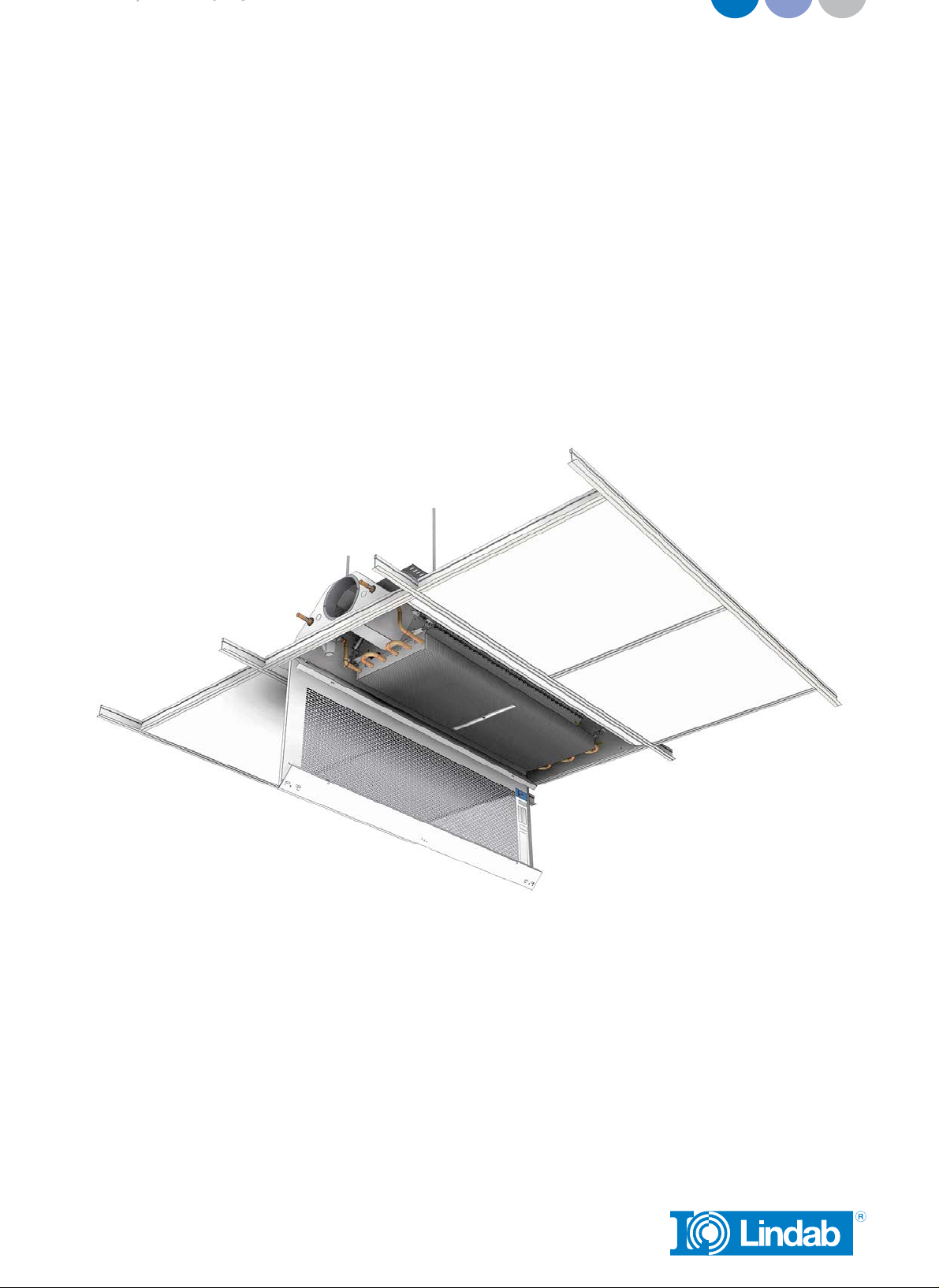
1.1 Product description
Lindab’s supply air beam Premum can be used for cooling, heating and ventilation.
Water valves, actuators, Regula Secura, Regula Combi and Regula Connect can all
be built into the Premum beam.
Premum feature the Lindab JetCone, a innovative way of regulating air volume. The
air volume can easily be adjusted without having to worry about pressure and noise
issues. And with the new adjustable AirGuide system, altering the flow pattern is
simpler than ever.
The Premum chilled beam is fully integratable with the Lindab eHybrid solution and
together they provide an optimal energy efficient ventilation and cooling solution
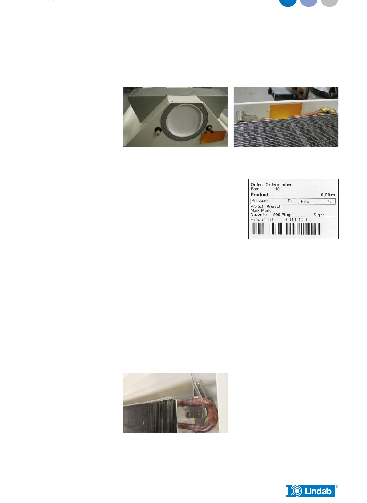
1.2 Handling
The beam must be handled with care, ensuring that the beam does not sustain dents,
scratches or bends during installation.
Always seek to lift the beam at multiple points.
– Do not lift in pipes
– Do not lift in edges
– Each beam is equipped with protective film to avoid any damage during transport
and handling at building site. The film needs to be removed before commissioning
the products.
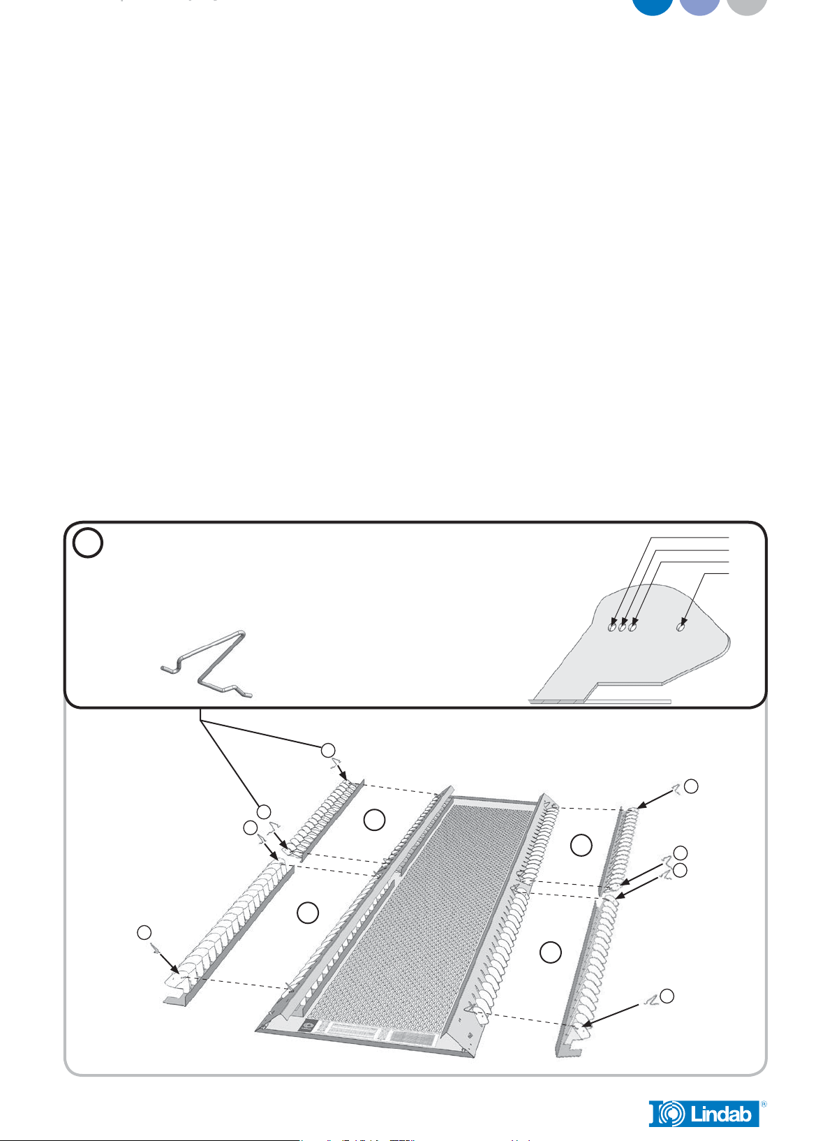
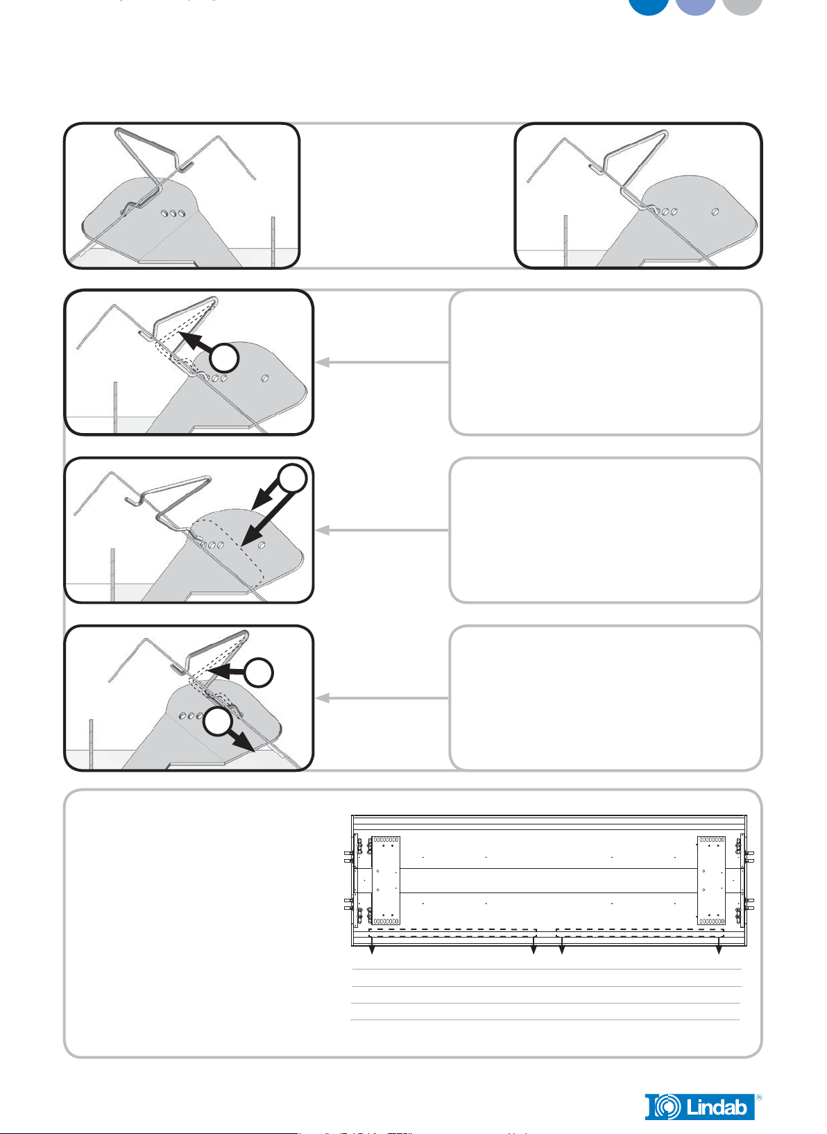
1.3 Mounting instruction
– Please visit www.lindqst.com
• Select Documentation Finder
• Select “Premum”
• Select “Mounting”
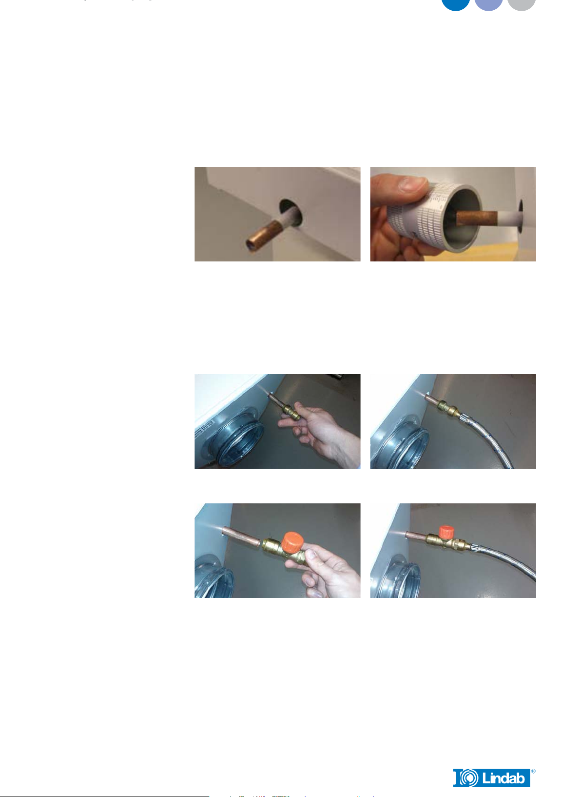
1.4 Air connection installation
The primary air supply should be connected with instructions from a ventilation spe-
cialist. Lindab’s chilled beams can beneficially be used together with Lindab’s Safe®
duct systems.
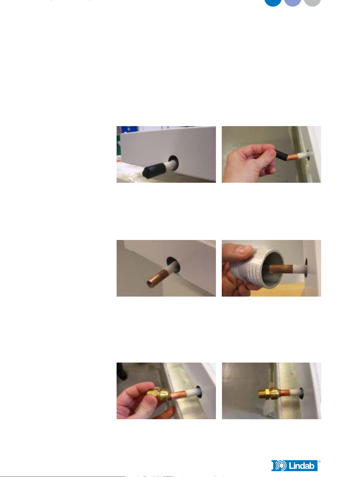
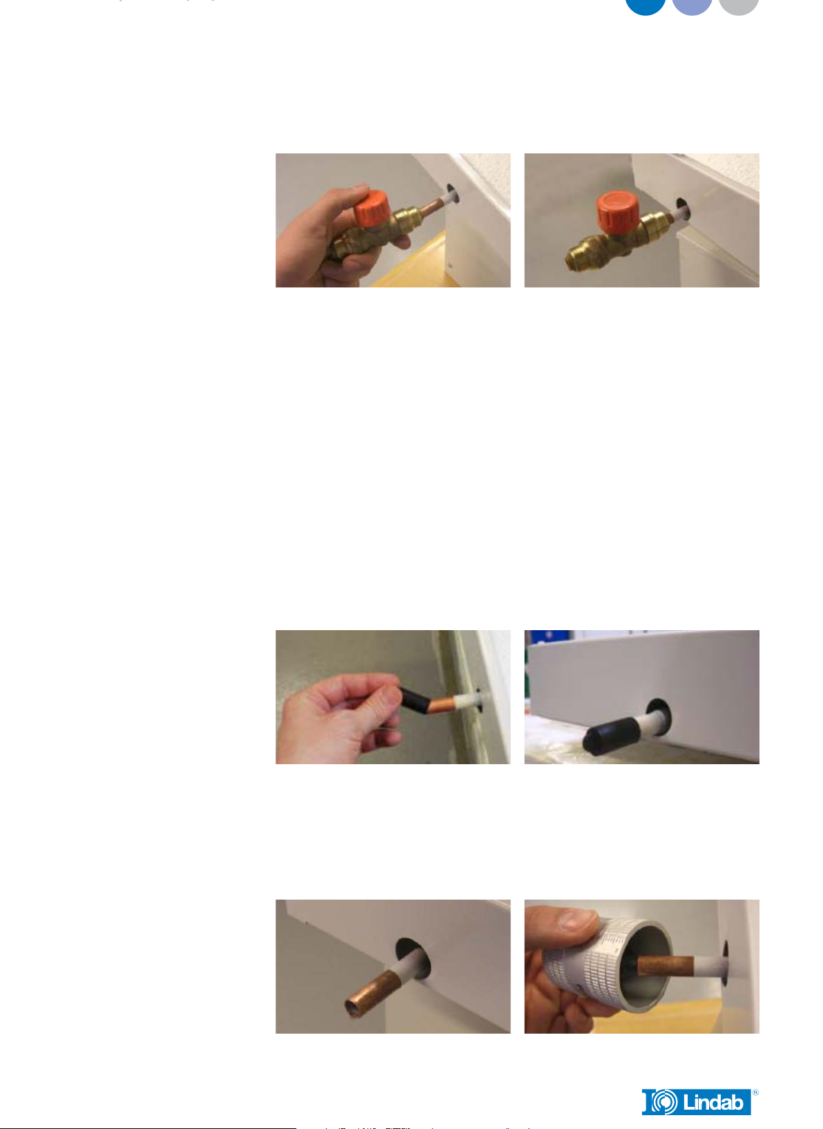
1.5 Connection description water
Flow indication arrows are shown on the inlet and return pipes in order to assist the
installer. If the beam has been ordered with integrated valves, a special direction
of the flow must be upheld to ensure correct flow through the thermostatic valve. If
the beam has been delivered without integrated valves, the flow can be reversed,
depending on the location of the retrofitted valve. Please note the flow direction indi-
cator on the valve to insure correct installation in relation to the desired flow.

Premum
3
|py
We reserve the right to make changes
1.5.1 Push-on fittings
– Please ensure that all pipes and fittings are undamaged, as even small dents and
scratches potentially pose a risk of leakage in the system. Always remember to do
a pressure test after assembly of the pipe work.
– Both flow and return pipe is covered by a plastic or rubber protection cover,
which should be removed before installation.
After removing the protection cover, make sure that the pipe is intact and undam-
aged, especially at the pipe end. Crocked or in other ways imperfect pipe ends will
result in leaks. Deburr the pipe on the inside and the outside, using a deburring tool
before installation
– Mount a push-on fitting to the pipe. Make sure to press the fitting all the way onto
the pipe. Consult the installation guide for the specific fitting for further details on
proper installation.
Push-on fitting

Premum
4
|py
We reserve the right to make changes
Push-on valve
Notice! The connection pipes are internally soft-welded why it’s not allowed to
solder the beam to the pipes.
1.5.2 Compression fitting
– Please ensure that all pipes and fittings are undamaged, as even small dents and
scratches potentially pose a risk of leakage in the system. Always remember to do
a pressure test after assembly of the pipe work.
– While mounting a compression fitting, the pipe will be exposed to a big amount
of force, creating a risk of crushing the pipe. To ensure that the pipe won’t be
crushed when mounting the compression fitting, a copper insert should be
inserted into the pipe.
– Both flow and return pipe is covered by a plastic or rubber protection cover
during transport, which must be removed before installation.
– After removing the protection cover, make sure that the pipe is intact and undam-
aged, especially at the pipe end. Crocked or in other ways imperfect pipe ends
will result in leaks. Deburr the pipe on the inside and the outside, using a deburr-
ing tool before installation

Premum
5
|py
We reserve the right to make changes
– The copper insert should be placed inside the pipe on the beam. Always support
the copper pipe coil when inserting the copper insert into position.
– Mount a compression coupling and/or a valve to the pipe. Don’t stress the nut too
much, since this may crush the pipe.
Notice! The connection pipes are internally soft-welded why it’s not allowed to solder
the beam to the pipes.
1.5.3 Flex hoses
Our flexible hoses can be used with both compression and Tectite fitting. We recom-
mend using Tectite fittings, for easier and faster mounting.
– Please ensure that all pipes and fittings are undamaged, as even small dents and
scratches potentially pose a risk of leakage in the system. Always remember to do
a pressure test after assembly of the pipe work.
– Both flow and return pipe is covered by a plastic or rubber protection cover,
which should be removed before installation.

Premum
6
|py
We reserve the right to make changes
After removing the protection cover, make sure that the pipe is intact and undam-
aged, especially at the pipe end. Crocked or in other ways imperfect pipe ends will
result in leaks. Deburr the pipe on the inside and the outside, using a deburring tool
before installation
– Mount a push-on fitting to the pipe. Make sure to press the fitting all the way onto
the pipe. After mounting the push-on fitting, mount the flexible hose. Make sure
that the flexible hose is pushed fully into the fitting. Consult the installation guide
for the specific fitting for further details on proper installation.
Push-on fitting
Push-on valve
Notice! The connection pipes are internally soft-welded why it’s not allowed to
solder the beam to the pipes.

Premum
7
|py
We reserve the right to make changes
2.0 Commissioning
2.1 Product labeling
Fig.1: Label location exterior (water connection) Fig.2: Label location interior (battery end).
On the label you’ll find:
– Order: Order identification number.
– Pos: Order position.
– Product: Product configuration.
– Project: Project name.
– Mark: Marking noted on order.
– Nozzles: Number of nozzles.
– Plugs: Number of plugged nozzles.
– Product ID: Product number.
– Sign: To be signed when checked and commissioned on site.
2.2 Measure air pressure and calculating the airflow.
Before calculating the airflow, the static nozzle pressure must first be measured. The
static nozzle pressure is the air pressure available at the nozzles.
2.2.1 Measure the static nozzle pressure.
– To measure the air pressure, a manometer, analog or digital (such as the Lindab
PC410) will be needed.
– Insert the measuring tube onto the specialized measuring nozzle
– Read off the static nozzle pressure from the manometer

Premum
8
40
50
40
80
90
60
70
100
20 3025
150
10
>3D@
[l/s]
50
159875 6
40
50
40
80
90
60
70
8060
100
20 3025
150
10
[Pa]
[l/s]
50 70
0123456789
15
9
8
7
|py
We reserve the right to make changes
2.2.2 Calculating the airflow
– After measuring the static nozzle pressure, read the setting of the four pins in the
corners to find the mean value of the pins.
– Locate the diagram on the faceplate or see diagram 1-2, and use the static nozzle
pressure and the mean value of the pins to find the current airflow.
Diagram 1
Diagram 2
Premum 1.2 m < L ≤ 2.0 m Position of JetCone adjustment pins
Premum 2.0 m < L ≤ 3.0 m Position of JetCone adjustment pins

Premum
9
30˚
20˚
10˚
0˚
3
2
1
4
A
A
A
A
A
A
A
A
AEach deflector has 2 adjustment “clips”.
hver deflektor har 2 justerings ”clips”.
Varje luftriktare har 2 justerings “clips”.
Jokaisessa ohjaimessa on kaksi pidäkeklipsiä.
Jedes Luftlenkelement ist mit zwei Klammern befestigt.
Ogni deflettore ha 2 clips di regolazione.
Chaque déflecteur a 2 clips d’ajustement.
Possible “clips” positions.
Mulige ”clips” positioner.
Möjliga “clips” positioner.
Mahdolliset pidäkeklipsien säätöasennot.
Mögliche Einstellungen.
Possibili posizionamenti delle clips.
Positions possibles des clips.
|py
We reserve the right to make changes
2.3 Changing the airflow
– Measure the static nozzle pressure
– Locate the air pressure/airflow diagram on the faceplate, or see diagram 1-2.
– Find the mean value of the four pins to reach the desired airflow, in the diagram
on the faceplate. Use the static nozzle pressure and the desired airflow to find the
mean value of the four pins.
– Adjust the four pins in the corners, so the mean value of the pins will correspond
with the mean value found in the diagram.
– Example: Pin setting: 6+6+8+8 = 28 / 4 = mean value 7.
2.4 Changing the air pattern (with plus feature AirGuide)
ONLY POSSIBLE IF THE BEAM WAS DELIVERED WITH AIRGUIDE
– Press the Airguide retaining clip to retract the clip from the Airguide deflector.
– Align the Airguide deflector in the desired position.
– Realease the Airguide retaining in the new position.

Premum
10
A
C
D
B
0˚ 30˚
30˚
20˚
30˚
0˚
10˚
10˚
30˚
0˚
10˚
10˚
30˚
0˚
30˚
20˚
30˚
0˚
Recommended configurations
Anbefalede konfigurationer
Rekommenderade konfigurationer
Suositellut säätöasennot
Emfohlene Einstellungen
Configurazioni raccomandate
Configurations recommandées
Example
Eksempel
Exempel
Esimerkki
Beispiel
Esempio
Exemple
Press and release “clips” from deflector position.
Tryk og frigør ”clips” fra deflektor position.
Tryck ihop och frisläpp Clipset från luftriktarpositionen.
Vapauta pidäkeklipsi ohjaimesta.
Klammer zusammendrücken und aushaken.
Premere e sganciare le clips dalla posizione corrente del deflettore.
Pousser et relâcher les “clips” de la position déflecteur.
Align deflector at desired position.
Tilpas deflektor til ønsket position.
Sätt luftriktaren i önskad position.
Säädä haluttuun asentoon.
Luftlenkelement in gewünschte Position bringen.
Regolare il deflettore nella posizione desiderata.
Aligner le déflecteur à la position souhaitée.
Press and release “clips” so it slips into new position.
Tryk og slip ”clips” så den glider ind i ny position.
Tryck och släpp clipset så att det glider in i sin nya position.
Kiinnitä pidäkeklipsi uuteen asentoon.
Klammer zusammendrücken und Klammer wieder einhaken.
Premere e rilasciare le clips nella nuova posizione.
Pousser et relâcher les “clips” à la nouvelle position.
|py
We reserve the right to make changes

Premum
11
|py
We reserve the right to make changes
3.0 Maintenance
The interval of cleaning depends on the indoor environment where the beam is placed.
Under optimal conditions the Premum beams only need cleaning every 5 years.
3.1 Cleaning instructions
– Remove the faceplate
– Clean underneath the battery with a vacuum cleaner and a piece of wet cloth
– Demount the inspection hatch in the opposite end of the air connection, in a turn
and pull motion.
– Clean the inside of the beam with a vacuum cleaner and a piece of wet cloth
– Only use lukewarm water and a mild detergent.
3.2 Models with down fold battery
– Remove the faceplate
– Unscrew the four screws on the battery, as described in the mounting instruc-
tion. Note that the two screws closest to the battery connection pipes must not
be completely unscrewed. Refer to the mounting instruction for details on this
matter.
– It is now possible to fold the battery down.

Premum
12
|py
We reserve the right to make changes
4.0 Product and system specification
4.1 Material data
Premum
Weight, kg/m 15
Water content, cooling, l/m 0,75
Water content, heating, l/m 0,25
Copper pipes, quality SS/EN 12449
Pressure class PN10
4.2 Environmental declaration
– Please visit www.lindqst.com
• Select Documentation Finder
• Select “Premum”
• Select “Environmental declaration”
4.3 Working and test pressure
– Lindab’s waterborne products have been manufactured and tested according to
the Pressure Equipment Directive 97/237EC. The products are classified as SEP –
Sound Engineering Practice.
– Pressure table
Pressure class PN10
Max. working pressure 10 bar
Max. recommended dynamic pressure 0,2 bar
Max. test pressure 16 bar
– Even though the battery of the chilled beam can withstand a very high static
working pressure, we recommend a much lower dynamic working pressure, to
avoid noise issues from the valves.
4.4 Water quality
– The water preparation and maintenance for the chilled beam water circuit should
be handled by a specialist
– To prevent corrosion, the water circuit must be airtight
– The water system must also be equipped with aerators to remove any build-up air
in the system.
– The water should be oxygen free, to prevent corrosion.
– The water system must be filled with potable water that complies with the “EC
directive 98/83/EC”.

Premum
13
|py
We reserve the right to make changes
– pH value of water must be between approximately 6-9 pH
– The water velocities should not exceed 1m/s, and should be kept as close to the
nominal flow as possible to minimize noise and optimize the energy yield
– There should be used in-line strainers to remove dirt particles from the water.
– If the water contains any additive inhibitor this must be appropriate to use with
copper and solder.
4.5 Air quality
– Primary supply air should be clean and filtered before reaching the beam.
4.6 Capacity test
– Lindabs active chilled beams are Eurovent-certified and tested according
to EN-15116.

Support
Hjælp
Hjälp
Tuotetuki
Unterstützung
Supporto
UK - Here you can find product updates/mounting instruc-
tions and support telephone number/mail.
www.lindab.com
Right to alterations reserved.
DK - Her kan du finde seneste produkt opdateringer/mon-
tagevejledninger samt support tlf. nr/mail.
www.lindab.dk
Ret til ændringer forbeholdes.
SE - Här kan du alltid hitta senaste produktuppdater-
ingarna/montageanvisningarna samt support tel. /e-mail.
www.lindab.se
Rätt till ändringar förbehålles.
FI - Täältä löydät uusimmat tuotetiedot ja asennusohjeet
sekä tuotetuen yhteystiedot.
www.lindab.fi
Oikeus muutoksiin pidätetään.
DE - Hier finden Sie aktuelle Produktinformationen/ Mon-
tageanleitungen und Telefonnummer/ E-Mail-Adressen der
Ansprechpartner.
www.lindab.de
Änderungen vorbehalten.
IT - Qui potete trovare istruzioni di montaggio, informa-
zioni sul prodotto ed un supporto tecnico qualificato
www.lindab.it
Soggetto a modifica senza obbligo di preavviso.
FR - Vous trouverez les fiches produits ou de montage
actualisées ainsi que les coordonnées du support télépho-
nique à l’adresse suivante :
www.lindab.fr
Toutes modifications réservées.
Do you have trouble finding your local contacts
please go to:
www.lindab.com
Premum-09072014
www.lindab.com
Table of contents
Popular Plumbing Product manuals by other brands

Glacier bay
Glacier bay 67552-1001 Use and care guide

Hans Grohe
Hans Grohe Talis S 32020001 Features & dimensions

SeasonsComfort
SeasonsComfort Anchor Point 158063 manual

ArtCeram
ArtCeram Fuori Scala Tondo TFL032 quick start guide

Glacier bay
Glacier bay HDQFP4F0005CP Installation and care guide

Graff
Graff G-11520 L1 Series manual

Haws
Haws 8320Axion Installation, operation & maintenance instructions

Tylo
Tylo HARMONY GF Assembly instruction

JohnsonSuisse
JohnsonSuisse Emilia FTW Suite JTTE401 installation instructions

Omnires
Omnires SYSYBI2BL Installation and Maintenance

Toto
Toto MERCER TL756DD owner's manual

miseno
miseno MNO1713 installation instructions