Lindgren-Pitman LS-5 Series User manual
LINDGREN-PITMAN, INC.
LS-5 Line Setter
MOUNTING
The Lindgren-Pitman Line Setter should be mounted on or near the transom of the boat such that the line will fall
overboard as it leaves the exit. The line setter may be mounted from the deck with optional mounting stand or
mounted to existing rigging if available.
HYDRAULIC REQUIREMENTS
12 GPM @ 1,500 PSI Maximum operating requirements
* The hydraulic source must be stable and uninterrupted. Additional equipment operating on this circuit may cause
pulsations unacceptable for smooth line setter operation. Hydraulic pulsations may cause the line to escape from
the rollers and contribute to accelerated roller wear.
Hydraulic Diagram - Super Spool III - LS-5 Line Setter

Freespooling Line From The Main Line Storage Spool
Correct freewheeling conditions are normally obtained by utilizing a Lindgren-Pitman direct drive monofilament long
line drum with a line setter pilot input circuit installed at the factory. Lindgren-Pitman monofilament type long line
spools not factory supplied with this circuit can be field retrofited. Monofilament long line spools with drives not
similar to Lindgren-Pitman equipment may or may not work properly with a line setter.
The main line storage spool must freespool easily and smoothly for the line setter to operate properly. The following
requirements should be met:
1. Freespooling should not require more than 50 Ibs. pull by the line setter at any spool diameter and at any
operating speed. Excessive freespooling force will cause accelerated roller wear.
2. Sufficient drag must be present to prevent backlashing.
3. Sufficient fleet angle from the spool to any block or the line setter is necessary to provide smooth freespooling.
START UP
Freespool or unwind enough main line to thread the line setter. Thread the line in the bottom between the two
vertical input rollers, under the first hour glass roller and continuing over and under each consecutive roller to the exit.
Set the speed control to the OFF (closed) position. Make sure that the main spool freespool valve is in the off or
closed position. Slowly close the on / off valve to start the setter. The speed can now be increased to the desired
setting by opening the speed adjustment valve. Opening the on /off valve will shut off the line setter. With the line
setter pilot control circuit installed on the main spool the line setter when loaded will freespool the main line spool
automatically. It will also brake the main spool when necessary.
Page 2
ATTACHING SNAPS
DANGER: Make certain the baited hook, leaded swivel and leader line are overboard before attaching snap
to mainline. Failure to follow these instructions could result in death or serious injury from entanglement in
the leader.
Attach snaps at least one foot away from line setter exit. Use a downward motion when attaching a snap or grab-
bing the line. Impeding the line near the exit may cause the line to jump off the internal drive rollers.
CONTROLS
Power
The pulling power of the line setter can be preset at the line setter. It is controlled by a pressure relief valve across
the motor hydraulic circuit. Loosening the jam or locking nut will allow for rotating the large set screw type adjust-
ment cap. Clockwise rotation will increase the pressure and pulling power and counter clockwise will decrease the
pressure and pulling power of the line setter. The pressure should be adjusted such that the drive motor does not
have sufficient power to slip the drive wheel but high enough to pull line from the spool at sufficient speed. If slipping
occurs the drive roller and the line will be damaged. Pressure factory set at 1000 PSI.
Speed
The line setter has a speed control mounted on the unit. The speed can be adjusted faster or slower to obtain the
desired line set. If sufficient speed cannot be obtained check for the following:
a. Hydraulic source has sufficient volume
b. Storage spool freewheels easily
c. Power control adjusted to a sufficient pressure
Speed Indicator (optional]
The Lindgren-Pitman line setter has a speed indicator programmed to display the line exit speed in knots and tenths
of a knot. It is powered by the magnetic pickup and requires no external power. With the use of an extension cable
from the magnetic pick up to the display unit it can be remote mounted.
The optional digital readout should display the line exit speed to the nearest tenth of a knot whenever the drive
wheels operate with an.update of approximately 1-2 seconds.
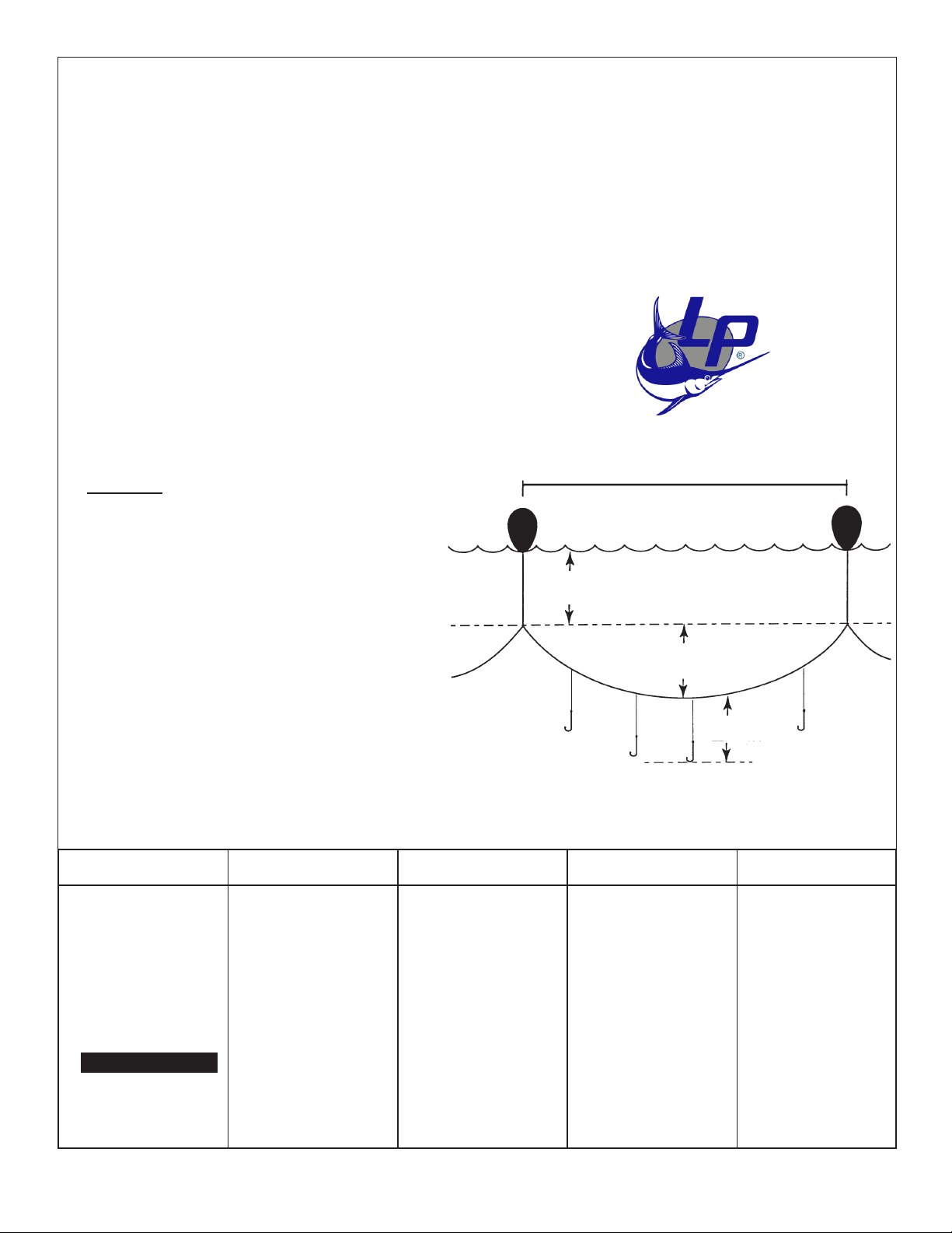
The depth of the line set is dependent upon the following factors:
1. Length of the buoy line.
2. The ratio of the line setter speed to the boat speed.
3. Distance between the buoys.
4. Length of the leader line.
The chart in the appendix will approximate the line depth using these four factors:
Page 3

Drive Wheel Replacement
The drive wheel rubber element will wear with use. When the line has worn a
groove in the drive roller element such that the drive roller will no longer grip the
line it must be replaced. To replace simply force the worn rubber drive element
off by prying under it with a screwdriver and discard. Install the new drive
element noting that the tapered inner surface of the drive element and the outer
surface of the drive wheel slope the same way.
ADJUSTMENT PROCEDURE FOR LINDGREN-PITMAN SPOOLS
USING LINE SETTERS
ìCounterbalance Adjustmentî
The Main line spool manifold has a counterbalance valve across the motor ports. The P2 port on the line setter is
connected to the signal port of this counterbalance. With the adjustment of the counterbalance full counterclock-
wise the pilot requires 1300 PSI before it will allow freespooling (if the line setter is set at 1000 PSI maximum
freespooling will not be possible). With the counterbalance full clockwise adjustment it would require only 330 PSI
before allowing freespooling. (This may not be enough for prevention of backlashing and sufficient braking).
The easy method to adjust the counterbalance is as follows:
1 Adjust the line setter power at approximately 1000 PSI, but not above 1300 PSI. Check pressure at the signal
line or pressure input with line threaded through the line setter and the line tied off to prevent rotation.
2 Thread line from the spool through the line setter by opening the ball valve on the spool.
3 Adjust the counterbalance full counterclockwise and close the ball valve.
4 Turn on the line setter slowly and let it pull on the spool line. The spool may not turn.
5 Turn the adjustment screw on the spool counterbalance slowly clockwise until the spool begins to freewheel.
Continue to adjust clockwise until the line setter reaches its set speed.
Further continued setting of the line may require the counter-balance to be rotated a little more clockwise and as the
spool diameter decreases. Usually a compromise setting can be found that runs smoothly with good~braking for the
entire set.
The further clockwise setting of the counterbalance will freespool with less line setter pull, but also with less braking
for slow down and stop.
Page 4
Page 5
Hook Depth Calculation Chart
For Use With Lindgren-Pitman LS-Series Line Setters
AB AB AB AB
To find the line setter speed setting, you
must know the distance between float buoys
and the desired sag of the main line be-
tween those floats.
1) Divide the desired sag by the
distance between floats,
2) Find the ratio in column A,
3) Multiply the boat speed by the
factor from column B.
Example:
With a distance of 1,800 feet between float
buoys and a desired additional main line
sag of 150 feet, the calculations would be
made as follows.
150' desired sag (divided by)
1,800' distance between floats
equals .08. Locate .08 in the chart from
column A, then multiply column B by the boat
speed which is 8 knots.
1.017 x 8 (knots) = 8.14 knots.
This is the speed setting on the line setter.
.41 1.401
.42 1.419
.43 1.437
.44 1.455
.45 1.474
.46 1.493
.47 1.512
.48 1.531
.49 1.551
.50 1.571
AB
.31 1.239
.32 1.254
.33 1.269
.34 1.284
.35 1.300
.36 1.316
.37 1.332
.38 1.349
.39 1.366
.40 1.383
.21 1.114
.22 1.124
.23 1.136
.24 1.147
.25 1.159
.26 1.171
.27 1.184
.28 1.197
.29 1.211
.30 1.225
.11 1.032
.12 1.038
.13 1.044
.14 1.051
.15 1.059
.16 1.067
.17 1.075
.18 1.084
.19 1.094
.20 1.103
.01 1.000
.02 1.001
.03 1.002
.04 1.004
.05 1.007
.06 1.010
.07 1.013
.08 1.017
.09 1.021
.10 1.026
Buoy Line Length
150í Additional Sag
Between Floats
Hook Line
Length
1,800 feet
Table of contents


