manuals.online logo
Brands
  1. Home
  2. •
  3. Brands
  4. •
  5. Linear Technology
  6. •
  7. Controllers
  8. •
  9. Linear Technology 1215 User manual

Linear Technology 1215 User manual

QUICK START GUIDE FOR DEMONSTRATION CIRCUIT 1215
5A, 15V, MONOLITHIC SYNCHRONOUS STEP-DOWN REGULATOR
1
LTC3605
DESCRIPTION
DESCRIPTIONDESCRIPTION
DESCRIPTION
Demonstration circuit 1215 is a step-down con-
verter, using the LTC3605 monolithic synchronous
buck regulator. The DC1215A has a maximum input
voltage 15V, and is capable of delivering up to 5A of
output current at a minimum input voltage of 4V.
The output voltage of the DC1215A can be set as
low as 0.6V, the reference voltage of the LTC3605.
At low load currents, the DC1215A operates in dis-
continuous mode, and during shutdown, it con-
sumes less than 10 uA of quiescent current. In
continuous mode operation, the DC1215A is a high
efficiency circuit - over 80%. The LTC3605 has
phase lock circuits, allowing high current multi-
phase operation of several DC1215As in parallel.
The DC1215A can also track another voltage with
the LTC3605 track function. Because of the high
switching frequency of the LTC3605, which is pro-
grammable up to 4 MHz, the DC1215A uses low
profile surface mount components. All these fea-
tures make the DC1215A an ideal circuit for use in
industrial applications and distributed power sys-
tems. Gerber files for this circuit are available.
Call the LTC Factory.
Design files for this circuit are available. Call
the LTC Factory
.
LTC is a trademark of Linear Technology Corporation
Table 1. Performance Summary (TA= 25°C)
PARAMETER CONDITIONS VALUE
Minimum Input Voltage 4V
Maximum Input Voltage 15V
GND = Shutdown
Run/Shutdown VIN = Run
VIN = 4V to 15V, IOUT = 0A to 5A 2.5V ±4% (2.4V – 2.6V)
VIN = 4.5V to 15V, IOUT = 0A to 5A 3.3V ±4% (3.168V – 3.432V)
Output Voltage VOUT Regulation
VIN = 6.4V to 15V, IOUT = 0A to 5A 5V ±4% (4.8V – 5.2V)
Typical Output Ripple VOUT VIN = 12V, VOUT = 2.5V, IOUT = 2.5A (20 MHz BW) < 40mVP–P
Discontinuous Mode VIN = 12V, VOUT = 2.5V < 2A
Nominal Switching Frequency RT= 162k 1 MHz
QUICK START GUIDE FOR DEMONSTRATION CIRCUIT 1215
5A, 15V, MONOLITHIC SYNCHRONOUS STEP-DOWN REGULATOR
2
QUICK START PROCEDUR
QUICK START PROCEDURQUICK START PROCEDUR
QUICK START PROCEDURE
EE
E
Demonstration Circuit 1215 is easy to set up to evalu-
ate the performance of the LTC3605. For proper
measurement equipment configuration, set up the
circuit according to the diagram in Figure 1
Figure 1Figure 1
Figure 1. Before
proceeding to test, insert shunts into the OFF position
of the RUN header JP7, the forced continuous mode
position (FCM) of the MODE header JP6, the 2 phase
position of the PHMODE header JP5, and the 3.3V
output voltage header, JP2.
When measuring the input or output voltage ripple,
care must be taken to avoid a long ground lead on the
oscilloscope probe. Measure the input or output volt-
age ripple by touching the probe tip directly across
the Vin or Vout and GND terminals. See Figure 2
Figure 2Figure 2
Figure 2 for
proper scope probe measurement technique.
With the DC1215 set up according to the proper
measurement configuration and equipment in Figure
FigureFigure
Figure
1
11
1, apply 6.3V at Vin (Do not hot-plug Vin or increase
Vin over the rated maximum supply voltage of 15V, or
the part may be damaged.). Measure Vout; it should
read 0V. Turn on the circuit by inserting the shunt in
header JP7 into the ON position. The output voltage
should be regulating. Measure Vout - it should
measure 2.5V +/- 2% (2.45V to 2.55V).
Vary the input voltage from 4V to 15V and adjust the
load current from 0 to 5A. Vout should read 2.5V +/-
4% (2.4V to 2.6V).
Adjust the output current to 5A. Measure the output
ripple voltage; it will measure less than 40 mVAC.
Observe the voltage waveform at the switch node
(pins 16 thru 19). Verify the switching frequency is
between 800 kHz and 1.2 MHz (T = 1.25 us and 0.833
us), and that the switch node waveform is rectangular
in shape.
Change the JP6 shunt from forced continuous mode
to discontinuous mode (DCM). Also set the input
voltage to 12V and the output current to any current
less than 1.5A. Observe the discontinuous mode of
operation at the switch node, and measure the output
ripple voltage. It should measure less than 150 mV.
Insert the JP7 shunt into the OFF position and move
the shunt in the 2.5V output JP1 header into any of
the two remaining output voltage option headers:
3.3V (JP2) or 5V (JP3). Just as in the 2.5V Vout test,
the output voltage should read Vout +/- 2% tolerance
under static line and load conditions and +/- 1% tol-
erance under dynamic line and load conditions (+/-
2% total). Also, the circuit operation in discontinu-
ous mode will be the same.
When finished, turn off the circuit by inserting the
shunt in header JP7 into the OFF position.
Low Output Voltage Configuration
For applications with output voltages less than 2V, the
inductor value of 1 uH on the DC1215 should be
changed to 0.33 uH. This is required so that the in-
ductor ripple current ramp has a large enough slope
for the current comparator can distinguish it from
noise voltages.
QUICK START GUIDE FOR DEMONSTRATION CIRCUIT 1215
5A, 15V, MONOLITHIC SYNCHRONOUS STEP-DOWN REGULATOR
3
Figure 1.
Figure 1.Figure 1.
Figure 1.
Proper Equipment Measurement Set
Proper Equipment Measurement SetProper Equipment Measurement Set
Proper Equipment Measurement Set-
--
-Up
UpUp
Up
Figure 2.
Figure 2.Figure 2.
Figure 2. Measuring Input or Output Ri
Measuring Input or Output RiMeasuring Input or Output Ri
Measuring Input or Output Rip
pp
pple
pleple
ple
QUICK START GUIDE FOR DEMONSTRATION CIRCUIT 1215
5A, 15V, MONOLITHIC SYNCHRONOUS STEP-DOWN REGULATOR
4
Normal Switching Frequency & Output Ripple Voltage
Normal Switching Frequency & Output Ripple VoltageNormal Switching Frequency & Output Ripple Voltage
Normal Switching Frequency & Output Ripple Voltage
Waveforms
WaveformsWaveforms
Waveforms
Figure 3.
Figure 3.Figure 3.
Figure 3. Switch Waveform & Output Ripple Voltage
Switch Waveform & Output Ripple VoltageSwitch Waveform & Output Ripple Voltage
Switch Waveform & Output Ripple Voltage
V
VV
V
IN
ININ
IN
=
==
= 12
1212
12V, V
V, VV, V
V, V
OUT
OUTOUT
OUT
=
==
= 2.5
2.52.5
2.5V, I
V, IV, I
V, I
OUT
OUTOUT
OUT
=
==
= 5
55
5A
AA
A, Fsw = 1 MHz
, Fsw = 1 MHz, Fsw = 1 MHz
, Fsw = 1 MHz
Trace 3: Output Ripple Voltage (20 mV/div AC)
Trace 3: Output Ripple Voltage (20 mV/div AC)Trace 3: Output Ripple Voltage (20 mV/div AC)
Trace 3: Output Ripple Voltage (20 mV/div AC)
Trace 1: Switch Voltage (5 V/div)
Trace 1: Switch Voltage (5 V/div)Trace 1: Switch Voltage (5 V/div)
Trace 1: Switch Voltage (5 V/div)
QUICK START GUIDE FOR DEMONSTRATION CIRCUIT 1215
5A, 15V, MONOLITHIC SYNCHRONOUS STEP-DOWN REGULATOR
5
Load Step Response Wav
Load Step Response WavLoad Step Response Wav
Load Step Response Wave
ee
eform
formform
form
Figure 4.
Figure 4.Figure 4.
Figure 4. Load Step Response
Load Step ResponseLoad Step Response
Load Step Response
V
VV
V
IN
ININ
IN
= 12V, V
= 12V, V= 12V, V
= 12V, V
OUT
OUTOUT
OUT
= 2.5V, 5A Load Step (0A <
= 2.5V, 5A Load Step (0A <= 2.5V, 5A Load Step (0A <
= 2.5V, 5A Load Step (0A <-
--
->
>>
> 5A)
5A)5A)
5A)
Forced Continuous Mode
Forced Continuous ModeForced Continuous Mode
Forced Continuous Mode Fsw = 1 MHz
Fsw = 1 MHzFsw = 1 MHz
Fsw = 1 MHz
Trace 3: Output Voltage (100mV/di
Trace 3: Output Voltage (100mV/diTrace 3: Output Voltage (100mV/di
Trace 3: Output Voltage (100mV/div AC)
v AC)v AC)
v AC)
Trace 4: Output Current (2
Trace 4: Output Current (2Trace 4: Output Current (2
Trace 4: Output Current (2A/div)
A/div)A/div)
A/div)
QUICK START GUIDE FOR DEMONSTRATION CIRCUIT 1215
5A, 15V, MONOLITHIC SYNCHRONOUS STEP-DOWN REGULATOR
6

Other Linear Technology Controllers manuals

Linear Technology LT8570 Quick setup guide

Linear Technology

Linear Technology LT8570 Quick setup guide

Linear Technology LTC3810-5 User manual

Linear Technology

Linear Technology LTC3810-5 User manual

Linear Technology LTC3729 User manual

Linear Technology

Linear Technology LTC3729 User manual

Linear Technology DC1736A Quick setup guide

Linear Technology

Linear Technology DC1736A Quick setup guide

Linear Technology LTC4000 User manual

Linear Technology

Linear Technology LTC4000 User manual

Linear Technology Analog Devices LTM4676A Quick setup guide

Linear Technology

Linear Technology Analog Devices LTM4676A Quick setup guide

Linear Technology DC1588A Quick setup guide

Linear Technology

Linear Technology DC1588A Quick setup guide

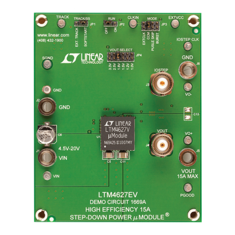
Linear Technology DC1669A Quick setup guide

Linear Technology

Linear Technology DC1669A Quick setup guide

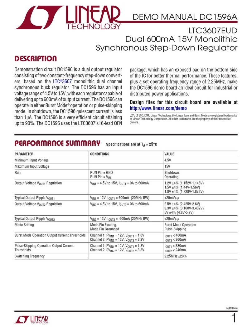
Linear Technology DC1596A Quick setup guide

Linear Technology

Linear Technology DC1596A Quick setup guide

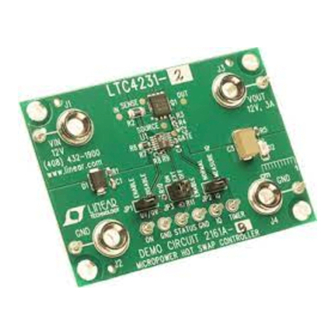
Linear Technology LTC4231 Quick setup guide

Linear Technology

Linear Technology LTC4231 Quick setup guide

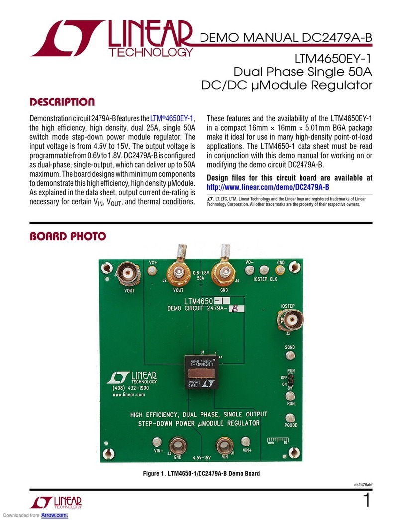
Linear Technology LTM4650EY-1 Quick setup guide

Linear Technology

Linear Technology LTM4650EY-1 Quick setup guide

Linear Technology DC 1090A User manual

Linear Technology

Linear Technology DC 1090A User manual

Linear Technology Analog Devices LT8708-1 User manual

Linear Technology

Linear Technology Analog Devices LT8708-1 User manual

Linear Technology LTM4616 Quick setup guide

Linear Technology

Linear Technology LTM4616 Quick setup guide

Linear Technology DC1488A Series User manual

Linear Technology

Linear Technology DC1488A Series User manual

Linear Technology LTC4232 Quick setup guide

Linear Technology

Linear Technology LTC4232 Quick setup guide

Linear Technology LTM4612 User manual

Linear Technology

Linear Technology LTM4612 User manual

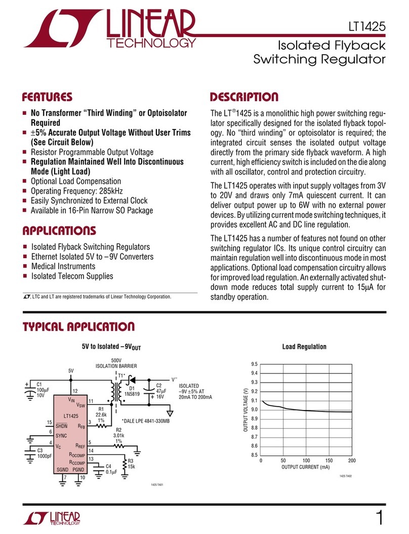
Linear Technology LT1425 User manual

Linear Technology

Linear Technology LT1425 User manual

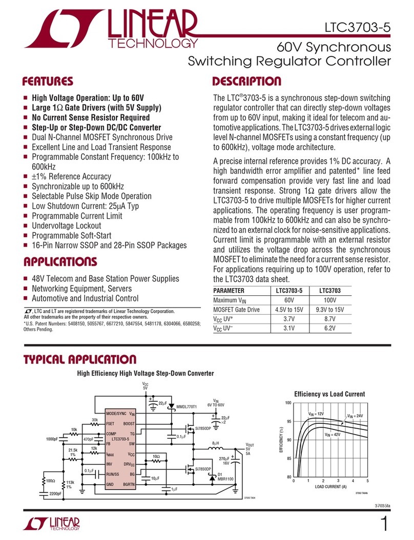
Linear Technology LTC3703-5 User manual

Linear Technology

Linear Technology LTC3703-5 User manual

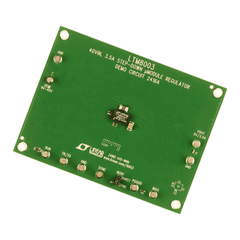
Linear Technology LTM8003 Quick setup guide

Linear Technology

Linear Technology LTM8003 Quick setup guide

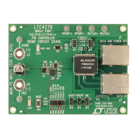
Linear Technology DC2541A Quick setup guide

Linear Technology

Linear Technology DC2541A Quick setup guide

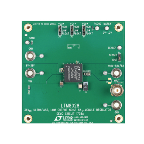
Linear Technology DC1738A Quick setup guide

Linear Technology

Linear Technology DC1738A Quick setup guide

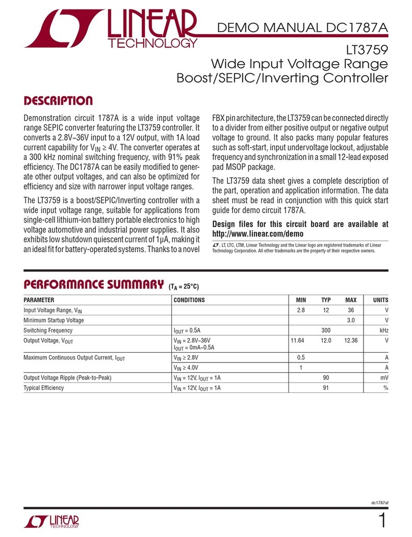
Linear Technology LT3759 Quick setup guide

Linear Technology

Linear Technology LT3759 Quick setup guide

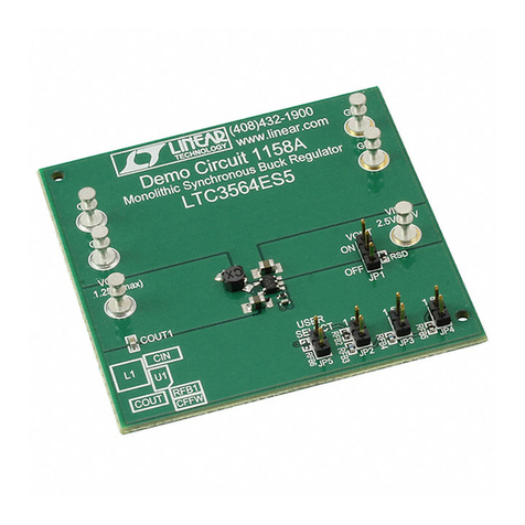
Linear Technology 1158A User manual

Linear Technology

Linear Technology 1158A User manual

Popular Controllers manuals by other brands

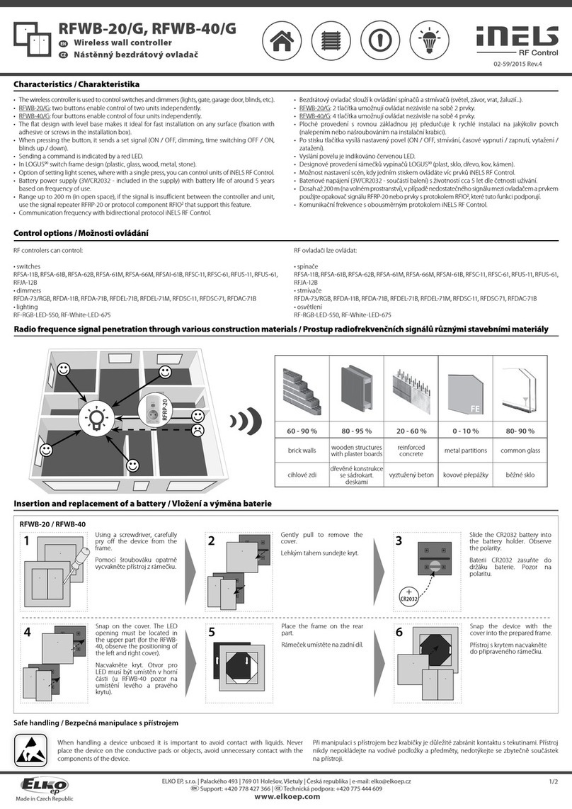
iNels RFWB-20/G quick start guide

iNels

iNels RFWB-20/G quick start guide

ST STM8AF6223 user manual

ST

ST STM8AF6223 user manual

INFOSEC Z1 Zenergy Cube EX user guide

INFOSEC

INFOSEC Z1 Zenergy Cube EX user guide

Hayward HLPMPCONV installation manual

Hayward

Hayward HLPMPCONV installation manual

HYDRO-RAIN HRC-390-06-NA instruction manual

HYDRO-RAIN

HYDRO-RAIN HRC-390-06-NA instruction manual

Newport SMC100CC user manual

Newport

Newport SMC100CC user manual

Heatit Controls Z-PUSHaZ-PUSH 45 126 92 Installer manual

Heatit Controls

Heatit Controls Z-PUSHaZ-PUSH 45 126 92 Installer manual

ABB i-bus SA/S 12.16.6.1 product manual

ABB

ABB i-bus SA/S 12.16.6.1 product manual

SpeedyBee F745 35A BLS AIO user manual

SpeedyBee

SpeedyBee F745 35A BLS AIO user manual

West Penn Wire AV-IP-NC811 Operation manual

West Penn Wire

West Penn Wire AV-IP-NC811 Operation manual

EuroLite LED C-1 user manual

EuroLite

EuroLite LED C-1 user manual

Intellijel Tete user manual

Intellijel

Intellijel Tete user manual

OEG KMS-D manual

OEG

OEG KMS-D manual

MOTECK MK35 manual

MOTECK

MOTECK MK35 manual

Sinovo SD300-2S-0.7G user manual

Sinovo

Sinovo SD300-2S-0.7G user manual

ActronAir QUE QZW-100 Installation and user manual

ActronAir

ActronAir QUE QZW-100 Installation and user manual

Bug-O Systems AVC-2100 Series Instructions and parts manual

Bug-O Systems

Bug-O Systems AVC-2100 Series Instructions and parts manual

Ambient Lockit Timecode manual

Ambient

Ambient Lockit Timecode manual

manuals.online logo
manuals.online logoBrands
  • About & Mission
  • Contact us
  • Privacy Policy
  • Terms and Conditions

Copyright 2025 Manuals.Online. All Rights Reserved.