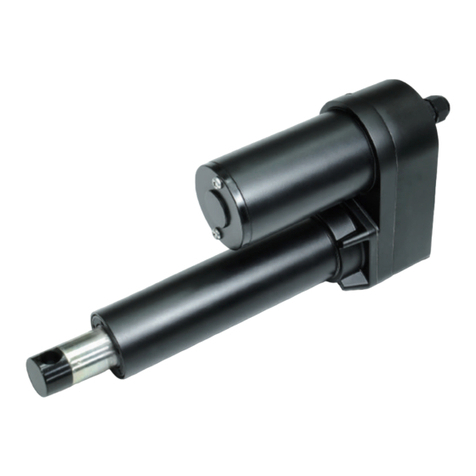
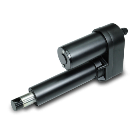
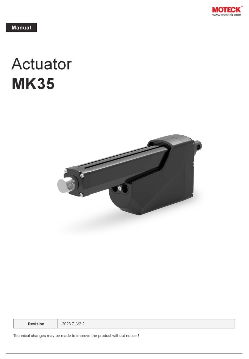
MOTECK MK35 User manual

Technical changes may be made to improve the product without notice!
2022.5_V1.0
www.moteck.com
Revision
Actuator
MK35

www.moteck.com
2
1. General
2. Important Information
3. Installation
3.1 Product label
3.2 Terminology
3.3 Working environment
3.4 Mechanical installation
3.5 Electrical installation
3.6 Installation and operation of control options
4. CAN Bus SAE J1939 Protocol
4.1 Summary
4.2 Network management
4.3 Command and status feedback
5. Troubleshooting
6. Performance and Options
6.1 Performance data
6.2 Ordering key
3
4
5
5
5
6
9
10
18
18
20
24
25
26
__________________________________________
___________________________
___________________________________
____________________________________
____________________________
___________________________
_____________________________
___________
______________________________________
____________________________
_____________________
_________________________________
_______________________________
____________________________________

www.moteck.com
3
1.1 About the manual
This manual is the mechanical and electrical installation instructions of MK35 electric linear actuator, and
also includes performance data and details of the optional specifications. Please read the instructions
carefully before installing the actuator. The installation work must be performed by qualified personnel,
which is very important.
1.2 Target readers
This manual is not provided to the end user, but provides information to the system or equipment manu-
facturer that uses this product with information on how to install, configure and maintain this product. The
system or equipment manufacturer must have qualified electromechanical personnel to perform it, and is
responsible for transmitting relevant safety messages to the end user.
1.3 Symbol description
1.4 Transport and storage
Please use the original packaging provided by MOTECK to transport and store the actuators. The tem-
perature during transportation and storage must be between -40°C to 80°C (-40°F to +176°F) and the
cargo must be protected from collision. If you find that the packaging of the delivered goods is damaged,
please check whether the actuators inside are obviously damaged, and notify the transporter. If neces-
sary, please contact the shipper or seller to discuss the disposal.
1. General
This symbol indicates important information, reminders, or safety warnings.
Symbol Descriptions

www.moteck.com
4
Only qualified personnel are allowed to carry out the mechanical and elec-
trical installation of this product. Qualified personnel should be familiar with
the mechanical or electrical installation work and have corresponding work
qualifications.
Please read this manual before installing or operating the actuators.
Do not perform mechanical installation when the actuator is powered. Com-
plete the mechanical installation first, and then perform the electrical instal-
lation.
Do not hold the extension tube when the device is powered on.
Installers and operators must wear personal safety protection according to
the site conditions. And before starting to control the action of the actuator,
it must be noted that the actuator and its connected mechanical moving
parts are not blocked by other objects, and no one enters the dangerous
area.
Strictly follow the information in this manual and the product label of the
actuators, and do not exceed the performance limits of the specification.
Never disconnect any wires or connectors during operation or when power
is applied.
If you find the actuator any malfunction or damage, please stop using it
immediately and notify qualified personnel to take corrective measures.
Do not disassemble the actuator. Otherwise, the sealing and function of the
actuator will be damaged.
There may be grease on the extension tube. It is harmless to touch the
grease, and the grease should not be removed.
●
●
●
●
●
●
●
●
●
●
2. Important Information

www.moteck.com
5
: MK35
: 24V DC
: 10000N (Push/Pull)
: 15%
Type
Input voltage
Max. Load
Duty cycle
S/N: 1201200001
Model No. MK35-24G-30B-1000-J00-110000
IP66 (dynamic)
IP67 (static), IP69K
3. Installation
3.1 Product label
The product label is located on the side of the outer tube. It tells you the actuator model and basic
specification. Before performing any installation or maintenance on the actuator, please check the
product label to determine the actuator type. If you need any help from MOTECK, please provide the
serial number and actuator model.
3.2 Terminology
3.3 Working environment
%
Max. temp. +80°C Min. temp. -40°C IP67/IP69K Relative humidity 10 ~ 90%
non-condensing
: MK35
: XXV DC
: XXXXN (Push/Pull)
: XX%
Type
Input voltage
Max. Load
Duty cycle
S/N: 1YYMMXXXXX
Model No. MK35-XXG-XXB-XXXX-SXX-XXX00X
IP66 (dynamic)
IP67 (static), IP69K
Power cable
Signal cable
Anti-pull lid
Housing
Front connector
Extension tube
Rear connector
Hand crank connector
Outer tube
Product label

www.moteck.com
6
14.5
8.1
ø30
ø13
14.5 13
8.1
ø30
ø12.2
ø30
ø13
17.7
ø30
ø12.2
17.7
ø25.4
14.513
8.1
ø13
ø25.4
14.513
8.1
ø12.2
ø13
ø25.4
21.513
ø12.2
ø25.4
21.5
11.5
13
11.5
13
3.4 Mechanical installation
3.4.1 Safety notes
3.4.2 Basic installation considerations
(1) Always use only the holes of the front and rear connectors to install the actuator. First check the model
number on the product label (section 3.1), and then refer to the model coding (section 6.2) to identify the
connector type of the actuator, so that you can find the dimensions specification from the figures below.
●Front connector types
❶Solid, ø12.2mm ❷ Slot, ø12.2mm ❸Solid, ø13mm ❹Slot, ø13mm
●Rear connector types
❶Solid, ø12.2mm ❷ Slot, ø12.2mm ❸Solid, ø13mm ❹Slot, ø13mm
(2) Make sure the actuator is installed in a way that allows you to access the anti-pull lid so that it can be
removed to plug in and out the cables (section 3.4.4)
(3) Users may need to manually adjust the actuator in the future, so there must be enough free space around the
manual drive connector to operate it (section 3.4.5)
●Do not perform mechanical installation when the actuator is powered.
●Complete the mechanical installation properly before proceeding to the
electrical installation steps.

www.moteck.com
7
X
X
X X
3.4.3 Force and orientation
(1) The actuator can be installed in any orientation and can withstand push and pull loads.
(2) When installing the actuator, make ensure that the force of the load acts on the central axis of the extension tube
and rear connector.
(3) Use only solid and sized mounting pins. The mounting pins must be strong enough to support the load and
prevent it from falling off after installation.
(4) The mounting pins must be parallel to each other on the same plane, as shown in the sketch below.
(5) If the actuator is used on the equipment to rotate with the mounting pin as the axis, it must be ensured the
housing and other mechanical parts will not interfere and damage the actuator and equipment in the full range
of movement.
3.4.4 Cables and anti-pull lid
Before the actuator is shipped, the power cord and signal cable have been plugged in and the anti-pull lid has been
installed. Only the CAN Bus version (control option J00) needs to remove this lid and unplug the power cord when
manually changing the address through hardware (see 4.2.2.2). But please note that when installing the actuator,
you must ensure that there is enough space to remove the anti-pull lid with tools.

3.4.5 Installation and operation of hand crank
(1) When installing the actuator, please make sure that there is enough space between the rear connector and any
objects behind it so that the hand crank can be operated.
(2) Please use a flat-head screwdriver to remove the cover and connect with a 6mm hexagon socket.
(3) Use a wrench to operate as a hand crank.
(4) Under the maximum load of the actuator, the maximum torque required to drive the extension tube with the
hand crank is about 1.4Nm.
(5) The distance traveled by the actuator per rotation of the hand crank is related to the gear ratio options of the
actuator. Please refer to the table below.
www.moteck.com
8
3.4.3 Force and orientation
(1) The actuator can be installed in any orientation and can withstand push and pull loads.
(2) When installing the actuator, make ensure that the force of the load acts on the central axis of the extension tube
and rear connector.
(3) Use only solid and sized mounting pins. The mounting pins must be strong enough to support the load and
prevent it from falling off after installation.
(4) The mounting pins must be parallel to each other on the same plane, as shown in the sketch below.
(5) If the actuator is used on the equipment to rotate with the mounting pin as the axis, it must be ensured the
housing and other mechanical parts will not interfere and damage the actuator and equipment in the full range
of movement.
3.4.4 Cables and anti-pull lid
Before the actuator is shipped, the power cord and signal cable have been plugged in and the anti-pull lid has been
installed. Only the CAN Bus version (control option J00) needs to remove this lid and unplug the power cord when
manually changing the address through hardware (see 4.2.2.2). But please note that when installing the actuator,
you must ensure that there is enough space to remove the anti-pull lid with tools.
Gear type
10
15
20
30
mm /rev
1.349
0.804
0.609
0.379
●Before using the hand crank, be sure to turn off the actuator power. Do not
apply torque exceeding 1.7Nm on the hand crank.
●Do not move the extension tube to both ends of the stroke, otherwise the
actuator might be damaged.
●Do not use any type of automatic drill or power tools to drive the manual
crank.

3.5 Electrical installation
3.5.1 Safety notes
3.5.2 Important information
3.5.3 Fuse specification
Install a slow-blow fuse of this specification between the actuator and the power supply for protection.
3.5.4 Electrical connections
Actuator is equipped with a power cable and a signal cable. One end of each cable has been plugged and fixed
on the actuator before shipment, and the other end are bare wire contacts for customers to connect power and
signal transmission. Please check the model number on the product label (section 3.1) first, then refer to the
model coding (section 6.2) to identify the control options of the actuator, and connect the power cable and signal
cable correctly according to the description of each control option (section 3.6).
www.moteck.com
9
●If users extend the power cord, Make sure that your own power extension
cord can withstand the maximum operating current of the actuator.
●It is recommended to install an emergency stop switch at a suitable location
of the power supply line.
●Do not perform wiring without cutting off the power supply.
●Before controlling the action of the actuator, it must be noted that the
actuator and its connected mechanical moving parts are not blocked by
other objects, and no one enters the dangerous area.
● It is forbidden to wind the signal cable with the power cable to avoid
interference with the signal.
● Avoid using the vehicle as a ground to reduce the risk of interference.
● The longer the power cord length or the smaller the wire diameter, the
worse the voltage drop. When the voltage of the power supply is low, it is
more likely to cause insufficient voltage and cause malfunctions.
● Relays or other coils on operating equipment should have spark protection
to avoid interference.
● Do not install or wire the actuator without cutting off the power supply.
●Before using the hand crank, be sure to turn off the actuator power. Do not
apply torque exceeding 1.7Nm on the hand crank.
●Do not move the extension tube to both ends of the stroke, otherwise the
actuator might be damaged.
●Do not use any type of automatic drill or power tools to drive the manual
crank.
Input voltage
12V DC
Fuse specification
40A
24V DC 20A
3.5.5 Power cord specification
To avoid malfunctions caused by voltage drop, the cross-section of the power cord must be large enough. The
cross-section of the MK35 power cord is 2.0mm² (14AWG) and the maximum length is 3 meters. If the customer
must connect an extension cord, the length and cross-section requirements of the extension cord are as follows.
3.5.6 Inrush current
3.6 Installation and operation of control options
3.6.1 Input voltage
It is forbidden to adjust the input voltage in an attempt to control the speed of the MK35 actuator. The battery or
full-wave rectified DC power used must be within acceptable voltage range, otherwise the actuator will stop
operating. If pulse width modulation (PWM) is used as the input power of MK35, it will cause malfunctions and
cause permanent damage.
3.6.2 Determine control options
MK35 actuator is equipped with one of the control options in the table below. Please check the model number on
the product label (section 3.1), and then refer to the model coding (section 6.2) to identify the control options of
the actuator. Then check the corresponding sections in the table below for more details.
*Remarks: End of stroke signal output
www.moteck.com
10
Options
S0L
SPL
SHL
J00
Control platform
Signal control
J1939 CAN Bus
Potentiometer
output
3.6.3
3.6.4
3.6.5
3.6.6
Section
Hall signal
output
* EoS
signal output
Motion status
feedback
●When the actuator starts, an inrush current of about 0.2 seconds will be
generated. The starting inrush current of MK35 can reach 3 times of the
maximum current under the rated load of the actuator.
●If a circuit board power supply is used, the specifications must be sufficient
to handle the inrush current. If batteries are used as the power source,
inrush current will not be a problem. Besides, the connectors, switches and
relays selected by user must also be able to withstand the inrush current.
Minimum cross section
4mm² (AWG 12)
Maximum length
4m

www.moteck.com
11
3.6.3 Control option S0L (signal control, with EoS signal output)
Option S0L uses a low current (<10mA) input signal to control the extension, retraction or stop of the actuator,
without switching the polarity of the input DC power, and there is an arrival signal output when it reaches the end of
stroke (EoS). However, if the user does not need EoS signal, these two signal output wires can be ignored and
unconnected. This does not affect the other functions of the actuator, and the actuator will still stop when it reaches
the limit positions at both ends of the stroke.
In addition, the actuator also has the following functions:
● At both ends of the mechanical stroke and within the full stroke range, when the current exceeds the factory
preset value of the rated load (overload condition), the actuator will automatically stop.
● When the input voltage exceeds its normal working range, the actuator will stop running. After the correct
voltage input is restored, the operation signal must be re-sent to restore control.
● With automatic soft start function, make the equipment move smoothly.
Wiring:
Wire definitions: S0L
Remarks: All dashed lines are connected by the customer.
Connect Red to positive.
Connect Black to negative.
Do not swap the polarity.
Input voltage: 12/24V±20%
Connect Black to positive (same as V+) to extend.
Vin= 5~32V
Connect Red to positive (same as V+) to extend.
Vin= 5~32V
Output= GND (Normally close circuit)
Output= Vcc (End of Stroke, open circuit)
The stroke limit switches are open collector circuit, and the arrival
signal output is not potential free. A 10KΩ pull-up resistor should be
applied in user’s control circuit.
Recommended input voltage is 5~24V
Power
cable
DescriptionDefinition
V-
Actuator
retracts
Actuator
extends
Not used
Not used
Not used
Wire color
Black
Blue
White
Red
Black
Yellow
Not used
Not used
Not used
Extend EoS
Retract EoS
Fuse
V+
V-
Extend
Retract
Vcc
Vcc
V+Red
Extend EoS
output
Green
Retract EoS
output
Orange
Signal
cable

www.moteck.com
12
3.6.4 Control option SPL
(signal control, with EoS signal output and potentiometer positioning output)
In addition to all the functions included in the S0L option (section 3.6.3), the SPL option is also equipped with a
potentiometer, which allows the user's control device to know the absolute position of the actuator at any time, and
can be used to determine the speed and direction of the actuator's movement.
Wiring:
Vin
POT output
GND
Extend EoS
Retract EoS
Fuse
V+
V-
Extend
Retract
Vcc
Vcc
Remarks: All dashed lines are connected by the customer.
●The potential value of the mechanical potentiometer can be measured
through the signal wires. This value is only related to the stroke position.
Even if the power supply is interrupted, it will not change the measurable
potential value.
●The user's automatic control device can use linear correlation to obtain the
absolute position information of the actuator.
●In order to achieve the longest service life, the actuator should not be
stopped by frequent hard collisions. Before the actuator moves to the target
position or both ends of the stroke, the user's automatic control device
should cut off the power of the motor in advance according to the absolute
position information, and use the inertia to make the actuator stop gently.

www.moteck.com
13
Wire definitions: SPL
Connect Red to positive.
Connect Black to negative.
Do not swap the polarity.
Input voltage: 12/24V±20%
Connect Red to positive (same as V+) to extend.
Vin= 5~32V
Power
cable
DescriptionWire color
Black
Red
Yellow
White
The recommended voltage is the same as V+, 12/24V±20%
1. Potentiometer specification:
- 10K ohm, 10 turns.
- Tolerance ±5%
2. Output voltage: The voltage (resistance) between
Blue and White increases linearly from about 0 when
the actuator extends, and decreases when it retracts.
3. There are different resolutions according to the stroke
length (as table below)
Note: For strokes over 950mm, the SHL option is recommended.
Actuator extends
Y
W
B
Blue
Stroke range (mm)
100~450
451~950
Red
Connect Black to positive (same as V+) to extend.
Vin= 5~32V
Black
Definition
V-
Actuator
extends
Vin
Orange Retract EoS
output
Green Extend EoS
output
GND
POT output
V+
Actuator
retracts
Output= GND (Normally close circuit)
Output= Vcc (End of Stroke, open circuit)
The stroke limit switches are open collector circuit, and the arrival
signal output is not potential free. A 10KΩ pull-up resistor should be
applied in user’s control circuit.
Recommended input voltage is 5~24V
Resolution (ohm/mm)
20
10
Signal
cable

www.moteck.com
14
Hall 2 output
Hall 1 output
GND
Extend EoS
Retract EoS
Fuse
V+
V-
Extend
Retract
Vcc
Vcc
Remarks: All dashed lines are connected by the customer.
3.6.5 Control option SHL
(signal control, with EoS signal output and dual Hall effect sensors feedback)
In addition to all the functions of the S0L option (section 3.6.4), the SHL option is also equipped with dual Hall effect
sensors.
Wiring:
The Hall feedback is a relative positioning. And each MK35 actuator has been
pre-calibrated before it is completed and shipped. Although the position
information will not be affected by power-off, it is still recommended that the
users retract the actuator to the end from time to time so that the positioning is
always automatically calibrated.

www.moteck.com
15
Hall 1
Hall 2
High
Low
High
Low
Hall 1
Hall 2
High
Low
High
Low
Actuator extends Actuator retracts
Wire definitions: SHL
Connect Red to positive.
Connect Black to negative.
Do not swap the polarity.
Input voltage: 12/24V±20%
Connect Black to positive (same as V+) to extend.
Vin= 5~32V
Connect Red to positive (same as V+) to extend.
Vin= 5~32V
Power
cable
DescriptionWire color
Red
Black
Red
Black
White
Resolution:
High= 10.8V (±0.6V)
Low= GND
Hall signal data:
Resolution (pulse/mm)
1.7598
2.9547
3.9035
6.2580
Output= GND (Normally close circuit)
Output= Vcc (End of Stroke, open circuit)
The stroke limit switches are open collector circuit, and the arrival
signal output is not potential free. A 10KΩ pull-up resistor should be
applied in user’s control circuit.
Recommended input voltage is 5~24V.
Definition
V+
V-
Actuator
retracts
Actuator
extends
Orange Retract EoS
output
Green Extend EoS
output
GND
10:1
15:1
20:1
30:1
Gear ratio
Yellow Hall 2 output
Blue Hall 1 output
Signal
cable

www.moteck.com
16
3.6.6 Control option J00 (for CAN Bus J1939 control system)
J00 option has full stroke positioning and speed control function. It is designed for CAN Bus platform, adopts the
SAE J1939 communication protocol and is suitable for applications of agriculture, construction and industrial auto-
mation. In addition to being controlled, the actuator can also return position, current, speed... and other status infor-
mation through the CAN Bus signal cable. Therefore, the users who choose the J00 option must have established
or prepared to establish the J1939 local area network control system to apply this actuator.
3.6.6.1 Preparation
Provide an individual power supply for MK35 actuator, separate from the power supply of the CAN Bus system (if
this power supply exists). All command and feedback message of the J00 option, including protection message, are
processed through CAN messages transmitted by the signal cable. Refer to Chapter 4 for information on J1939
operation and communication protocol.
Wiring:
Wire definitions: J00
3.6.6.2 Connect CAN Bus SAE J1939 system
Please follow the wiring guidelines of ISO-11898 standard CAN 2.0B, protocol SAE J1939. The two ends of the CAN
High / Low harness should be connected with a 120Ω terminal resistor, as shown in the figure below.
CAN High
CAN Low
120Ω
R
120Ω
R
CAN Bus actuator
MK35
Blue
Brown
Fuse
V+
V-
CAN Low
CAN High
Connect Red to positive.
Connect Black to negative.
Do not swap the polarity.
Input voltage: 12/24V±20%
Power
cable
DescriptionWire color
Black
Signal
cable Brown
Blue
ECU
Red
Definition
V-
CAN High
CAN Low
V+
Remarks: All dashed lines (fuse) are connected by the customer.

www.moteck.com
17
3.6.6.3 Offline operation
The actuator may need to be operated offline (via the CAN Bus network) for repair, maintenance and testing. Please
unplug the CAN High / Low signal cable from MK35, and then plug in another signal cable for offline operation (this
signal cable is not included and needs to be ordered separately).
Wiring:
Wire definitions:
Connect Red to positive.
Connect Black to negative.
Do not swap the polarity.
Input voltage: 12/24V±20%
Connect Black to positive (same as V+) to extend.
Vin= 5~32V
Connect Red to positive (same as V+) to extend.
Vin= 5~32V
Power
cable
DescriptionDefinition
V+
V-
Actuator
retracts
Actuator
extends
Not used
Not used
Not used
Wire color
Red
Black
Blue
White
Red
Black
Yellow
Not used
Not used
Not used
Not used
Not used
Fuse
V+
V-
Extend
Retract
Not used
Not usedGreen
Orange
Signal
cable
Remarks: All dashed lines are connected by the customer.

www.moteck.com
18
4. CAN Bus SAE J1939 Protocol
4.1 Summary
The content in this chapter assumes that the reader is familiar with the SAE J1939 standard. Therefore,
the terminology in the standard is used, but not described in detail.
MOTECK provides command information to control the actions and status feedback of MK35 actuator,
which complies with the following J1939 standards PGN.
4.2 Network management
4.2.1 J1939 NAME
64 bits were divided into 10 parameters
J1939-81 Network Management
J1939-21 Data Link Layer
Proprietary A
Proprietary B
Address Claimed / Cannot Claim
Commanded Address
61184 (0x00EF00)
65280 (0x01EF00)
60928 (0x00EE00)
65240 (0x00FED8)
Identity number
Manufacture code
Function instance
Function
Unique default address set by MOTECK
Assigned by SAE to MOTECK
ECU instance Cannot be changed
Cannot be changed
Cannot be changed
Reserved J1939 reserved
Vehicle system Non-specific system
Vehicle system instance Can be changed
Industry group Apply to all
Arbitrary Address Capable Accept the assigned address
Parameter
1.1
3.6
5.1
5.4
6.1
7.1
7.2
8.1
8.5
8.8
LSB
21
11
3
5
8
1
7
4
3
1
Length
(bit)
967
0
0
255
0
0
0
0
1
Note
Serial
Default
value
Please contact Moteck sales for information.

www.moteck.com
19
4.2.2 Address
The address is the basis for sending messages in the J1939 network, values from 0 to 253 are allowed as valid
addresses in the same network. The address of each control application (CA) in the same network must be unique.
The J1939 protocol defines that if the declared address is the same as other CA’s, it will be judged by NAME
(section 4.2.1), and the 64-bit data will be converted into a decimal value. The smaller value takes precedence in
obtaining the declared address.
4.2.2.1 Default address
MK35 has the “Arbitrary Address Capable” function, but the default address 16 will be set at the factory. In the case
of address conflict and low priority, MK35 will not be able to use the default address and will not automatically issue
a new address claim, but it can accept commanded address from main application of the system.
4.2.2.2 Change address from Hardware
If multiple MK35 actuators will be used in a CAN Bus network, in order to save initialization time, MK35 has a DIP
switch for address selection. Up to 16 MK35 actuators can be connected and preset addresses.
Before connecting the actuators to the bus, please follow the steps below.
(1) Loosen the screw of the anti-pull lid, and then remove the lid.
(2) Pull out the power cable, you can see the red DIP switch as shown in the figure below.
(3) Use a non-conductive stick to slide the 4 DIP switches. The hardware address settings are shown below,
which represent values from 16 (preset) to 31.
(4) Plug the power cable back in.
(5) Put the anti-pull lid back correctly and tighten the screws to ensure that the anti-pull lid is sealed.
OFF
1 2 3 4
DIP
ON
OFF
1 2 3 4
DIP
ON
OFF
1 2 3 4
DIP
ON
OFF
1 2 3 4
DIP
ON
OFF
1 2 3 4
DIP
ON
OFF
1 2 3 4
DIP
ON
OFF
1 2 3 4
DIP
ON
OFF
1 2 3 4
DIP
ON
OFF
1 2 3 4
DIP
ON
OFF
1 2 3 4
DIP
ON
OFF
1 2 3 4
DIP
ON
OFF
1 2 3 4
DIP
ON
OFF
1 2 3 4
DIP
ON
OFF
1 2 3 4
DIP
ON
17
23
29
16 (Preset)
22
28
18
24
30
19
25
31
20
26
21
27
OFF
1 2 3 4
DIP
ON
OFF
1 2 3 4
DIP
ON
Address Value
Please contact Moteck sales for information.

www.moteck.com
20
4.3 Command and status feedback
All control applications (CA) in the bus system can use the motion commands and parameters in the following table
that comply with the J1939 communication protocol to control MK35 actuators or receive status feedback through
the two signal lines of the CAN network system.
4.3.1 Proprietary A
All control application (CA) in the same network can send actions or setting command to MK35 through
Proprietary A. The parameters of all control parameters can be adjusted by Proprietary A. The requirements are as
follows:
(1) Transmission rate: 250 kbps
(2) Recommended data repetition rate: 100~250ms
(3) Protocol Data Unit (PDU):
●Priority: Default value 6
●Parameter Group Number (PGN): 61184 (0x00EF00)
*PS can be the default address (16) of MK35, or the hardware address (17~31) set
by the user (Section 4.2.2). Or it can be set to FF (255) as the broadcast mode.
●Source address (SA): The unique address of the J1939 controller application (i.e. ECU) that sends
this Proprietary A command.
●Data Field: 8 Bytes (64 bits) are divided into 5 parameters as following definition.
• Run forward (extend the actuator)
• Run backward (retract the actuator)
• Run to position
• Stop
• Position
• Current limit
• Run speed (PWM%)
• Soft start (ramp up time)
• Soft stop (ramp down time)
• Action status
• Present stroke position
• Present electric current
• Run speed (PWM%)
• Soft start/stop (ramp time)
• Error code
EDP
0
DP
0
PF
239
PS
(address) *
8 bits
Action
16 bits
Position
8 bits
Current
8 bits
Run speed
or
Set ramp
24 bits
Reserved
3 bits
Priority
1 bit
EDP
1 bit
DP
8 bits
PF
8 bits
PS
8 bits
SA
64 bits
Data
PGN
FeedbackMotion parametersMotion commands
Please contact Moteck sales for information.
Other manuals for MK35
1
Table of contents
Other MOTECK Controllers manuals

MOTECK
MOTECK 01US12 User manual

MOTECK
MOTECK ID10 User manual

MOTECK
MOTECK CB3T Operational manual

MOTECK
MOTECK ID12 User manual

MOTECK
MOTECK CM43 User manual

MOTECK
MOTECK 01US10 User manual

MOTECK
MOTECK MK35 User manual

MOTECK
MOTECK ID12 User manual

MOTECK
MOTECK IA5 User manual

MOTECK
MOTECK CIS1 User manual
Popular Controllers manuals by other brands

WAREMA
WAREMA KNX SA Series installation instructions

SECOP
SECOP 105N4866 operating instructions

Mitsubishi Electric
Mitsubishi Electric FX3U-7DM installation manual

Telect
Telect nrgCONTROL-BT installation guide

Netech
Netech MiniSim 330 instruction manual

maxon motor
maxon motor EPOS2 Module 36/2 Hardware reference