manuals.online logo
Brands
  1. Home
  2. •
  3. Brands
  4. •
  5. Linear Technology
  6. •
  7. Controllers
  8. •
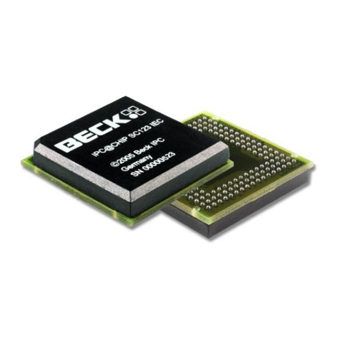
  9. Linear Technology LTC3810-5 User manual

Linear Technology LTC3810-5 User manual

LTC3810-5
1
38105fd
60V Current Mode
Synchronous Switching
Regulator Controller
The LTC
®
3810-5 is a synchronous step-down switching
regulator controller that can directly step-down voltages
from up to 60V, making it ideal for telecom and automo-
tive applications. The LTC3810-5 uses a constant on-time
valley current control architecture to deliver very low duty
cycles with accurate cycle-by-cycle current limit, without
requiring a sense resistor.
A precise internal reference provides 0.5% DC accuracy. A
high bandwidth (25MHz) error amplifier provides very fast
line and load transient response. Large 1Ω gate drivers
allow the LTC3810-5 to drive multiple MOSFETs for higher
current applications. The operating frequency is selected
by an external resistor and is compensated for variations
in VIN and can also be synchronized to an external clock
for switching-noise sensitive applications. A shutdown
pin allows the LTC3810-5 to be turned off, reducing the
supply current to 240µA.
Integrated bias control generates gate drive power from
the input supply during start-up or when an output short-
circuit occurs, with the addition of a small external SOT23
MOSFET. When in regulation, power is derived from the
output for higher efficiency.
n48V Telecom and Base Station Power Supplies
nNetworking Equipment, Servers
nAutomotive and Industrial Control Systems
nHigh Voltage Operation: Up to 60V
nLarge 1ΩGate Drivers
nNo Current Sense Resistor Required
nDual N-Channel MOSFET Synchronous Drive
nExtremely Fast Transient Response
n±0.5% 0.8V Voltage Reference
nProgrammable Output Voltage Tracking/Soft-Start
nGenerates 5.5V Driver Supply from Input Supply
nSynchronizable to External Clock
nSelectable Pulse Skip Mode Operation
nPower Good Output Voltage Monitor
nAdjustable On-Time/Frequency: tON(MIN) < 100ns
nAdjustable Cycle-by-Cycle Current Limit
nProgrammable Undervoltage Lockout
nOutput Overvoltage Protection
n5mm ×5mm QFN Package
High Efficiency High Voltage Step-Down Converter Efficiency vs Load Current
Typical applicaTion
FeaTures
applicaTions
DescripTion
L, LT, LTC, LTM, Linear Technology, the Linear logo and No RSENSE are registered trademarks
of Linear Technology Corporation. All other trademarks are the property of their respective
owners. Protected by U.S. Patents including 5481178, 5847554, 6304066, 6476589, 6580258,
6677210, 6774611.
PGOOD
MODE/SYNC
VRNG
ITH
VFB
SGND
SS/TRACK
ION
1000pF
47pF
5pF
VIN
13V TO 60V
22µF
VOUT
12V/6A
ZXMN10A07F
200k
LTC3810-5
EXTVCC
TG
SW
SENSE–
BG
BGRTN
SENSE+
DRVCC
INTVCC
NDRV
BOOST
38105 TA01
0.1µF
274k 100k
Si7450DP
Si7450DP
1µF
MBR1100
14k
1k
270µF
10µH
SHDN +
+
LOAD CURRENT (A)
0
85
EFFICIENCY (%)
90
95
100
12 3 4
38105 TA01b
5 6
VIN = 24V
VIN = 42V
LTC3810-5
2
38105fd
Supply Voltages
INTVCC, DRVCC ...................................... –0.3V to 14V
(DRVCC – BGRTN), (BOOST – SW)........ –0.3V to 14V
BOOST (Continuous).............................. –0.3V to 85V
BOOST (≤400ms) .................................. –0.3V to 95V
BGRTN........................................................ –5V to 0V
EXTVCC.................................................. –0.3V to 15V
(EXTVCC – INTVCC)..................................–12V to 12V
(NDRV – INTVCC) Voltage .......................... –0.3V to 10V
SW, SENSE+Voltage (Continuous).................–1V to 70V
SW, SENSE+Voltage (400ms)........................–1V to 80V
ION Voltage (Continuous)............................ –0.3V to 70V
ION Voltage (400ms)................................... –0.3V to 80V
SS/TRACK Voltage....................................... –0.3V to 5V
PGOOD Voltage............................................ –0.3V to 7V
VRNG, VON, MODE/SYNC, SHDN,
UVIN Voltages............................................ –0.3V to 14V
PLL/LPF, FB Voltages................................ –0.3V to 2.7V
TG, BG, INTVCC, EXTVCC RMS Currents ................50mA
Operating Junction Temperature Range (Notes 2, 3, 7)
LTC3810E-5 ....................................... –40°C to 125°C
LTC3810I-5 ........................................ –40°C to 125°C
LTC3810H-5....................................... –40°C to 150°C
Storage Temperature Range .................. –65°C to 125°C
(Note 1)
pin conFiguraTionabsoluTe MaxiMuM raTings
32
33
31 30 29 28 27 26 25
9 10 11 12
TOP VIEW
UH PACKAGE
32-LEAD (5mm ×5mm) PLASTIC QFN
13 14 15 16
17
18
19
20
21
22
23
24
8
7
6
5
4
3
2
1NC
VON
VRNG
PGOOD
MODE/SYNC
ITH
VFB
PLL/LPF
SENSE+
NC
NC
NC
SENSE–
BGRTN
BG
DRVCC
NC
ION
NC
NC
NC
BOOST
TG
SW
SS/TRACK
NC
NC
SHDN
UVIN
NDRV
EXTVCC
INTVCC
TJMAX = 125°C, θJA = 34°C/W
EXPOSED PAD (PIN 33) IS SGND, MUST BE SOLDERED TO PCB
orDer inForMaTion
LEAD FREE FINISH TAPE AND REEL PART MARKING* PACKAGE DESCRIPTION TEMPERATURE RANGE
LTC3810EUH-5#PBF LTC3810EUH-5#TRPBF 38105 32-Lead (5mm ×5mm) Plastic QFN –40°C to 125°C
LTC3810IUH-5#PBF LTC3810IUH-5#TRPBF 38105 32-Lead (5mm ×5mm) Plastic QFN –40°C to 125°C
LEAD BASED FINISH TAPE AND REEL PART MARKING PACKAGE DESCRIPTION TEMPERATURE RANGE
LTC3810EUH-5 LTC3810EUH-5#TR 38105 32-Lead (5mm ×5mm) Plastic QFN –40°C to 125°C
LTC3810IUH-5 LTC3810IUH-5#TR 38105 32-Lead (5mm ×5mm) Plastic QFN –40°C to 125°C
LTC3810HUH-5 LTC3810HUH-5#TR 38105 32-Lead (5mm ×5mm) Plastic QFN –40°C to 150°C
Consult LTC Marketing for parts specified with wider operating temperature ranges. *The temperature grade is identified by a label on the shipping container.
For more information on lead free part marking, go to: http://www.linear.com/leadfree/
For more information on tape and reel specifications, go to: http://www.linear.com/tapeandreel/
LTC3810-5
3
38105fd
SYMBOL PARAMETER CONDITIONS MIN TYP MAX UNITS
Main Control Loop
INTVCC INTVCC Supply Voltage l4.35 14 V
IQINTVCC Supply Current
INTVCC Shutdown Current
SHDN > 1.5V (Notes 4, 5)
SHDN = 0V
3
240
6
600
mA
µA
IBOOST BOOST Supply Current SHDN > 1.5V (Note 5)
SHDN = 0V
270
0
400
5
µA
µA
VFB Feedback Voltage (Note 4)
0°C to 85°C
–40°C to 85°C
–40°C to 125°C (I-Grade)
–40°C to 150°C (H-Grade)
l
l
l
l
0.796
0.794
0.792
0.792
0.792
0.800
0.800
0.800
0.800
0.800
0.804
0.806
0.806
0.808
0.812
V
V
V
V
V
DVFB,LINE Feedback Voltage Line Regulation 5V < INTVCC < 14V (Note 4) l0.002 0.02 %/V
VSENSE(MAX) Maximum Current Sense Threshold VRNG = 2V, VFB = 0.76V
VRNG = 0V, VFB = 0.76V
VRNG = INTVCC, VFB = 0.76V
256
70
170
320
95
215
384
120
260
mV
mV
mV
VSENSE(MIN) Minimum Current Sense Threshold VRNG = 2V, VFB = 0.84V
VRNG = 0V, VFB = 0.84V
VRNG = INTVCC, VFB = 0.84V
–300
–85
–200
mV
mV
mV
IVFB Feedback Current VFB = 0.8V 20 150 nA
AVOL(EA) Error Amplifier DC Open Loop Gain 65 100 dB
fUError Amp Unity-Gain Crossover
Frequency
(Note 6) 25 MHz
VMODE/SYNC MODE/SYNC Threshold VMODE/SYNC Rising 0.75 0.8 0.85 V
IMODE/SYNC MODE/SYNC Current MODE/SYNC = 5V 0 1 µA
VSHDN Shutdown Threshold 1.2 1.5 2 V
ISHDN SHDN Pin Input Current 0 1 µA
VUVIN UVIN Undervoltage Lockout UVIN Rising
UVIN Falling
Hysteresis
l
l
0.86
0.78
0.07
0.89
0.80
0.10
0.92
0.82
0.12
V
V
V
VVCCUV INTVCC Undervoltage Lockout
Linear Regulator Mode
External Supply Mode
Trickle-Charge Mode
INTVCC Rising, INDRV = 100µA
INTVCC Rising, NDRV = INTVCC = EXTVCC
INTVCC Rising, NDRV = INTVCC, EXTVCC = 0
INTVCC Falling
l
l
l
4.05
4.05
8.70
4.2
4.2
9
3.7
4.35
4.35
9.30
V
V
V
V
Oscillator and Phase-Locked Loop
tON On-Time ION = 100µA
ION = 300µA
1.55
515
1.85
605
2.15
695
µs
ns
tON(MIN) Minimum On-Time ION = 2000µA 100 ns
tOFF(MIN) Minimum Off-Time 250 350 ns
tON(PLL) tON Modulation Range by PLL
Down Modulation
Up Modulation
ION = 100µA, VPLL/LPF = 0.6V
ION = 100µA, VPLL/LPF = 1.8V
2.2
0.6
3.6
1.2
5
1.8
µs
µs
IPLL/LPF Phase Detector Output Current
Sinking Capability
Sourcing Capability
fPLLIN < fSW
fPLLIN > fSW
15
–25
µA
µA
Driver
IBG,PEAK BG Driver Peak Source Current VBG = 0V 0.7 1 A
RBG,SINK BG Driver Pull-Down RDS(ON) 1 1.5 Ω
ITG,PEAK TG Driver Peak Source Current VTG – VSW = 0 0.7 1 A
RTG,SINK TG Driver Pull-Down RDS(ON) 1 1.5 Ω
The ldenotes specifications which apply over the full operating
temperature range, otherwise specifications are at TA= 25°C (Note 2), INTVCC = DRVCC = VBOOST = VON = VRNG = SHDN = UVIN =
VEXTVCC = VNDRV = 5V, VMODE/SYNC = VSENSE+= VSENSE–= VBGRTN = VSW = 0V, unless otherwise specified.
elecTrical characTerisTics
LTC3810-5
4
38105fd
Note 1: Stresses beyond those listed under Absolute Maximum Ratings
may cause permanent damage to the device. Exposure to any Absolute
Maximum Rating condition for extended periods may affect device
reliability and lifetime.
Note 2: The LTC3810-5 is tested under pulsed load conditions such that
TJ≈ TA. The LTC3810E-5 is guaranteed to meet performance specifications
from 0°C to 85°C. Specifications over the –40°C to 125°C operating
junction temperature range are assured by design, characterization and
correlation with statistical process controls. The LTC3810I-5 is guaranteed
to meet performance specifications over the full –40°C to 125°C operating
junction temperature range. The LTC3810H-5 is guaranteed to meet
performance specifications over the full –40°C to 150°C operating junction
temperature range. High junction temperatures degrade operating lifetimes;
operating lifetime is derated for junction temperatures greater than 125°C.
Note 3: TJis calculated from the ambient temperature TAand power
SYMBOL PARAMETER CONDITIONS MIN TYP MAX UNITS
PGOOD Output
DVFBOV PGOOD Upper Threshold
PGOOD Lower Threshold
VFB Rising
VFB Falling
7.5
–7.5
10
–10
12.5
–12.5
%
%
DVFB,HYST PGOOD Hysterisis VFB Returning 1.5 3 %
VPGOOD PGOOD Low Voltage IPGOOD = 5mA 0.3 0.6 V
IPGOOD PGOOD Leakage Current VPGOOD = 5V 0 2 µA
PG Delay PGOOD Delay VFB Falling 120 µs
Tracking
ISS/TRACK SS/TRACK Source Current VSS/TRACK > 0.5V 0.7 1.4 2.5 µA
VFB,TRACK Feedback Voltage at Tracking VTRACK = 0V, ITH = 1.2V (Note 4)
VTRACK = 0.5V, ITH = 1.2V (Note 4)
0.48
–0.018
0.5
0.52
V
V
VCC Regulators
VEXTVCC EXTVCC Switchover Voltage
EXTVCC Rising
EXTVCC Hysterisis
l
4.45
0.1
4.7
0.25
0.4
V
V
VINTVCC,1 INTVCC Voltage from EXTVCC 6V < VEXTVCC < 15V 5.2 5.5 5.8 V
DVEXTVCC,1 VEXTVCC - VINTVCC at Dropout ICC = 20mA, VEXTVCC = 5V 75 150 mV
DVLOADREG,1 INTVCC Load Regulation from EXTVCC ICC = 0mA to 20mA, VEXTVCC = 10V 0.01 %
VINTVCC,2 INTVCC Voltage from NDRV Regulator Linear Regulator in Operation 5.2 5.5 5.8 V
DVLOADREG,2 INTVCC Load Regulation from NDRV ICC = 0mA to 20mA, VEXTVCC = 0 0.01 %
INDRV Current into NDRV Pin VNDRV – VINTVCC = 3V 20 40 60 µA
INDRVTO Linear Regulator Timeout Enable
Threshold
210 270 350 µA
VCCSR Maximum Supply Voltage Trickle Charger Shunt Regulator 15 V
ICCSR Maximum Current into NDRV/INTVCC Trickle Charger Shunt Regulator,
INTVCC ≤ 16.7V (Note 8)
10 mA
The ldenotes specifications which apply over the full operating
temperature range, otherwise specifications are at TA= 25°C (Note 2), INTVCC = DRVCC = VBOOST = VON = VRNG = SHDN = UVIN =
VEXTVCC = VNDRV = 5V, VMODE/SYNC = VSENSE+= VSENSE–= VBGRTN = VSW = 0V, unless otherwise specified.
dissipation PDaccording to the following formula:
LTC3810-5: TJ= TA+ (PD • 34°C/W)
Note 4: The LTC3810-5 is tested in a feedback loop that servos VFB to the
reference voltage with the ITH pin forced to a voltage between 1V and 2V.
Note 5: The dynamic input supply current is higher due to the power
MOSFET gate charging being delivered at the switching frequency
(QG • fOSC).
Note 6: Guaranteed by design. Not subject to test.
Note 7: This IC includes overtemperature protection that is intended
to protect the device during momentary overload conditions. Junction
temperature will exceed 150°C when overtemperature protection is active.
Continuous operation above the specified maximum operating junction
temperature may impair device reliability.
Note 8: ICC is the sum of current into NDRV and INTVCC.
Similar Parts Comparison
PARAMETER LTC3810 LTC3810-5 LTC3812-5
Maximum VIN 100V 60V 60V
MOSFET Gate Drive 6.35V to 14V 4.5V to 14V 4.5V to 14V
INTVCC UV+6.2V 4.2V 4.2V
INTVCC UV–6V 4V 4V
elecTrical characTerisTics
LTC3810-5
5
38105fd
Load Transient Response
Start-Up
Short-Circuit/
Fault Timeout Operation
Short-Circuit/
Foldback Operation
Tracking
Pulse Skip Mode Operation
Efficiency vs Input Voltage
Efficiency vs Load Current
Frequency vs Input Voltage
Typical perForMance characTerisTics
50µs/DIV
VOUT
100mV/DIV
IOUT
5A/DIV
38105 G01
VIN = 48V
0A TO 5A LOADSTEP
FRONT PAGE CIRCUIT
500µs/DIV
INTVCC
5V/DIV
VOUT
5V/DIV
VIN
50V/DIV
IL
5A/DIV
38105 G02
VIN = 48V
ILOAD = 1A
MODE/SYNC = 0V
FRONT PAGE CIRCUIT
INTVCC
10ms/DIV
VOUT
10V/DIV
SS/TRACK
4V/DIV
IL
5A/DIV
38105 G03
VIN = 48V
RSHORT = 0.1Ω
FRONT PAGE CIRCUIT
200µs/DIV
VOUT
5V/DIV
VFB
0.5V/DIV
IL
5A/DIV
38105 G04
VIN = 48V
FRONT PAGE CIRCUIT
500µs/DIV 38105 G05
VOUT
5V/DIV
SS/TRACK
0.5V/DIV
VFB
0.5V/DIV
IL
5A/DIV
VIN = 48V
ILOAD = 1A
MODE/SYNC = 0V
FRONT PAGE CIRCUIT
SS/TRACK
VFB
VOUT
100mV/DIV
ITH
0.5V/DIV
20µs/DIV 38105 G06
IL
2A/DIV
VIN = 48V
IOUT = 100mA
MODE/SYNC = INTVCC
FRONT PAGE CIRCUIT
INPUT VOLTAGE (V)
10 20
70
EFFICIENCY (%)
90
100
30 50 60
38105 G07
80
40 70 80
IOUT = 5A
IOUT = 0.5A
VOUT = 12V
Si7852 MOSFETs
f = 250kHz
LOAD CURRENT (A)
0
70
EFFICIENCY (%)
75
80
85
90
100
1234
38105 G08
5 76
95
VOUT = 5V
Si7850 MOSFETs
MODE/SYNC = INTVCC
f = 250kHz
VIN = 12V VIN = 36V
VIN = 60V
INPUT VOLTAGE (V)
10 20
230
FREQUENCY (kHz)
250
280
30 50 60
38105 G09
240
270
260
40 70 80
IOUT = 0A
IOUT = 5A
MODE/SYNC = 0V
FRONT PAGE CIRCUIT
LTC3810-5
6
38105fd
Frequency vs Load Current
Current Sense Threshold
vs ITH Voltage
On-Time vs ION Current
On-Time vs VON Voltage
On-Time vs Temperature
Current Limit Foldback
Maximum Current Sense
Threshold vs VRNG Voltage
Maximum Current Sense
Threshold vs Temperature
Reference Voltage vs
Temperature
Typical perForMance characTerisTics
LOAD CURRENT (A)
0
250
300
350
4
38105 G10
200
150
1 2 3 5
100
50
0
FREQUENCY (kHz)
FORCED
CONTINUOUS
PULSE SKIP
ITH VOLTAGE (V)
0
CURRENT SENSE THRESHOLD (mV)
–100
0
100
1.5 2.5
38105 G11
–200
–300
–400 0.5 1.0 2.0
200
300
400
3.0
VRNG = 2V
1.4V
1V
0.7V
0.5V
ION CURRENT (µA)
10
10
ON-TIME (ns)
100
1000
10000
100 1000 10000
38105 G12
VON = INTVCC
VON VOLTAGE (V)
0
400
500
700
1.5 2.5
38105 G13
300
200
0.5 1 2 3
100
0
600
ON-TIME (ns)
ION = 300µA
TEMPERATURE (°C)
–50
ON-TIME (ns)
640
660
680
25 75
38105 G14
620
600
–25 0 50 100 150125
580
560 ION = 300µA
VFB (V)
0
MAXIMUM CURRENT SENSE THRESHOLD (mV)
100
150
0.8
38105 G15
50
00.2 0.4 0.6
250
200
VRNG = INTVCC
VRNG VOLTAGE (V)
0.5
MAXIMUM CURRENT SENSE THRESHOLD (mV)
200
38105 G16
100
01 1.5
300
400
2–50 25 75–25 0 50 100 150125
TEMPERATURE (°C)
180
MAXIMUM CURRENT SENSE THRESHOLD (mV)
200
230
38105 G17
190
220
210
VRNG = INTVCC
–50 25 75–25 0 50 100 150125
TEMPERATURE (°C)
REFERENCE VOLTAGE (V)
0.801
0.802
0.803
38105 G18
0.800
0.799
0.798
0.797
LTC3810-5
7
38105fd
Driver Peak Source Current
vs Temperature
Driver Pull-Down RDS(ON)
vs Temperature
Driver Peak Source Current
vs Supply Voltage
Driver Pull-Down RDS(ON)
vs Supply Voltage
EXTVCC LDO Resistance at
Dropout vs Temperature
INTVCC Current vs Temperature
INTVCC Shutdown Current
vs Temperature
INTVCC Current vs INTVCC Voltage
Typical perForMance characTerisTics
–50 25 75–25 0 50 100 150125
TEMPERATURE (°C)
0.5
PEAK SOURCE CURRENT (A)
1.0
1.5
38105 G19
VBOOST = VINTVCC = 5V
–50 25 75–25 0 50 100 150125
TEMPERATURE (°C)
RDS(ON) (Ω)
1.25
1.50
1.75
38105 G20
1.00
0.75
0.50
0.25
VBOOST = VINTVCC = 5V
DRVCC/BOOST VOLTAGE (V)
4 5 7 9 11 13
PEAK SOURCE CURRENT (A)
3.0
2.5
2.0
1.5
1.0
0.5
06 8 10 12
38105 G21
14
DRVCC/BOOST VOLTAGE (V)
4
RDS(ON) (Ω)
0.6
0.8
0.9
1.0
1.1
689 1413
38105 G22
0.7
5 7 10 11 12 –50 25 75–25 0 50 100 150125
TEMPERATURE (°C)
4
5
7
38105 G23
3
2
1
0
6
RESISTANCE (Ω)
–50 25 75–25 0 50 100 150125
TEMPERATURE (°C)
1
INTVCC CURRENT (mA)
2
5
4
3
–50 25 75–25 0 50 100 150125
TEMPERATURE (°C)
INTVCC CURRENT (µA)
38105 G25
200
100
0
400
300
INTVCC = 5V
INTVCC VOLTAGE (V)
0
2.0
2.5
3.5
6 10
38105 G26
1.5
1.0
2 4 8 12 14
0.5
0
3.0
INTVCC CURRENT (mA)
LTC3810-5
8
38105fd
INTVCC Shutdown Current
vs INTVCC Voltage
SS/TRACK Pull-Up Current
vs Temperature
ITH Voltage
vs Load Current
Shutdown Threshold
vs Temperature
Typical perForMance characTerisTics
INTVCC VOLTAGE (V)
0
200
250
300
6 10
38105 G27
150
100
2 4 8 12 14
50
0
INTVCC CURRENT (µA)
–50 25 75–25 0 50 100 150125
TEMPERATURE (°C)
SS/TRACK CURRENT (µA)
2
3
38105 G28
1
0
LOAD CURRENT (A)
0
2.0
3.0
2.5
3 5
38105 G29
1.5
1.0
1 2 4 6 7
0.5
0
ITH VOLTAGE (V)
VRNG = 1V
FRONT PAGE CIRCUIT
–50 25 75–25 0 50 100 150125
TEMPERATURE (°C)
SHUTDOWN THRESHOLD (V)
2.0
38105 G30
1.4
1.0
0.8
0.6
2.2
1.8
1.6
1.2
LTC3810-5
9
38105fd
pin FuncTions
VON (Pin 2): On-Time Voltage Input. Voltage trip point
for the on-time comparator. Tying this pin to the output
voltage or to an external resistive divider from the output
makes the on-time proportional to VOUT. The comparator
defaults to 0.7V when the pin is grounded and defaults to
2.4V when the pin is connected to INTVCC. Tie this pin to
INTVCC in high VOUT applications to use a lower RON value.
VRNG (Pin 3): Sense Voltage Limit Set. The voltage at this
pin sets the nominal sense voltage at maximum output
current and can be set from 0.5V to 2V by a resistive di-
vider from INTVCC. The nominal sense voltage defaults to
95mV when this pin is tied to ground, and 215mV when
tied to INTVCC.
PGOOD (Pin 4): Power Good Output. Open-drain logic
output that is pulled to ground when the output voltage
is not between ±10% of the regulation point. The output
voltage must be out of regulation for at least 120µs before
the power good output is pulled to ground.
MODE/SYNC (Pin 5): Pulse Skip Mode Enable/Sync Pin.
This multifunction pin provides pulse skip mode enable/
disable control and an external clock input to the phase
detector. Pulling this pin below 0.8V or to an external
logic-level synchronization signal disablespulse skip mode
operation and forces continuous operation. Pulling this
pin above 0.8V enables pulse skip mode operation. For a
clock input, the phase-locked loop will force the rising top
gate signal to be synchronized with the rising edge of the
clock signal.This pin can also be connected to a feedback
resistor divider from a secondary winding on the inductor
to regulate a second output voltage.
ITH (Pin 6): Error Amplifier Compensation Point and Cur-
rent Control Threshold. The current comparator threshold
increases with this control voltage. The voltage ranges
from 0V to 2.6V with 1.2V corresponding to zero sense
voltage (zero current).
VFB (Pin7):Feedback Input. Connect VFB through a resistor
divider network to VOUT to set the output voltage.
PLL/LPF (Pin 8): The phase-locked loop’s lowpass filter
is tied to this pin. The voltage at this pin defaults to 1.2V
when the IC is not synchronized with an external clock at
the MODE/SYNC pin.
SS/TRACK (Pin9): Soft-Start/Tracking Input. For soft-start,
a capacitor to ground at this pin sets the ramp rate of the
output voltage (approximately 0.6s/µF). For coincident or
ratiometric tracking, connect this pin to a resistive divider
between the voltage to be tracked and ground.
SHDN (Pin 12): Shutdown Pin. Pulling this pin below
1.5V will shut down the LTC3810-5, turn off both of the
external MOSFET switches and reduce the quiescent sup-
ply current to 240µA.
UVIN (Pin 13): UVLO Input. This pin is input to the internal
UVLO and is compared to an internal 0.8V reference. An
external resistor divider is connected to this pin and the
input supply to program the undervoltage lockout voltage.
When UVIN is less than 0.8V, the LTC3810-5 is shut down.
NDRV (Pin 14): Drive Output for External Pass Device of
the Linear Regulator for INTVCC. Connect to the gate of
an external NMOS pass device and a pull-up resistor to
the input voltage VIN.
EXTVCC (Pin 15): External Driver Supply Voltage. When
this voltage exceeds 4.7V, an internal switch connects this
pin to INTVCC through an LDO and turns off the exter nal
MOSFET connected to NDRV, so that controller and gate
drive are drawn from EXTVCC.
INTVCC (Pin 16): Main Supply Pin. All internal circuits ex-
cept the output drivers are powered from this pin. INTVCC
should be bypassed to ground (Pin 10) with at least a 0.1µF
capacitor in close proximity to the LTC3810-5.
DRVCC (Pin 17): Driver Supply Pin. DRVCC supplies power
to the BG output driver. This pin is normally connected to
INTVCC. DRVCC should be bypassed to BGRTN (Pin 20)
with a low ESR (X5R or better) 1µF-10µF capacitor in close
proximity to the LTC3810-5.
LTC3810-5
10
38105fd
pin FuncTions
BG (Pin 18): Bottom Gate Drive. The BG pin drives the
gate of thebottom N-channelsynchronous switch MOSFET.
This pin swings from BGRTN to DRVCC.
BGRTN (Pin 19): Bottom Gate Return. This pin connects to
the source of the pulldown MOSFET in the BG driver and
is normally connected to ground. Connecting a negative
supply to this pin allows the synchronous MOSFET’s gate
to be pulled below ground to help prevent false turn-on
during high dV/dt transitions on the SW node. See the
Applications Information section for more details.
SENSE+, SENSE–(Pin 24, Pin 20): Current Sense Com-
parator Input. The (+) input to the current comparator is
normally connected to SW unless using a sense resistor.
The (–) input is used to accurately kelvin sense the bottom
side of the sense resistor or MOSFET.
SW (Pin 25): Switch Node Connection to Inductor and
Bootstrap Capacitor. The voltage swing at this pin is –0.7V
(a Schottky diode (external) voltage drop) to VIN.
TG (Pin 26): Top Gate Drive. The TG pin drives the gate of
the top N-channel synchronous switch MOSFET. The TG
driver draws power from the BOOST pin and returns to the
SW pin, providing true floating drive to the top MOSFET.
BOOST (Pin 27): Top Gate Driver Supply. The BOOST pin
supplies power to the floating TG driver. BOOST should
be bypassed to SW with a low ESR (X5R or better) 0.1µF
capacitor. An additional fast recovery Schottky diode from
DRVCC to the BOOST pin will create a complete floating
charge-pumped supply at BOOST.
ION (Pin 31): On-Time Current Input. Tie a resistor from VIN
to this pin to set the one-shot timer current and thereby
set the switching frequency.
SGND (Exposed Pad Pin 33): Signal Ground. All small-
signal components should connect to this ground and
eventually connect to PGND at one point.
LTC3810-5
11
38105fd
FuncTional DiagraM
–
+
–
+
1.4V
FAULT
0.7V
FB
VRNG
3
–
+
–+
+
–
+
VVON
IION
tON = (76pF)
R
S Q
20k
ICMP IREV
×
SHDN
SWITCH
LOGIC
BG
ON
FCNT
OV
1.5V
EA
0.8V
12
38105 FD
SGND
RFB1
RFB2
12
RUN
SHDN
18
BGRTN
19
PGOOD
VFB
DRVCC
17
SENSE+
24
SW
25
TG
BOOST
CB
26
27
EXTVCC
15
INTVCC
NDRV
16
14
–
+
–
+
UV
0.72V
OV
0.88V
CVCC
VOUT
M2
M1
M3
L1
COUT
CIN
+
SS/TRACK
DB
4
+
+
VIN
VIN
SENSE–
20
–
+
OVERTEMP
SENSE
FOLDBACK
0.8V
REF
5V
REG
INTVCC
ITH’
5
8
ION
31
VIN
VIN
2
VON
PLL/LPF
MODE/SYNC
UVIN
RON
0.8V
RUV1
RUV2
–
+
F
TIMEOUT
LOGIC
INTVCC
MODE
LOGIC
NDRV
EXTVCC INTVCC
PLL-SYNC
–
+
VIN UV
13
–
+
INTVCC
UV
DRV OFF
100nA
1.4µA
270µA
–
+
–
+
OFF
ON
5.5V
4.7V
4.2V
9V
5.5V
SHDN
2.6V 4V
ITH
CC2
6
RC
CC1
9
7
LTC3810-5
12
38105fd
Main Control Loop
The LTC3810-5 is a current mode controller for DC/
DC step-down converters. In normal operation, the top
MOSFET is turned on for a fixed interval determined by
a one-shot timer (OST). When the top MOSFET is turned
off, the bottom MOSFET is turned on until the current
comparator ICMP trips, restarting the one-shot timer and
initiating the next cycle. Inductor current is determined
by sensing the voltage between the SENSE–and SENSE+
pins using a sense resistor or the bottom MOSFET on-
resistance. The voltage on the ITH pin sets the comparator
threshold corresponding to the inductor valley current.
The fast 25MHz error amplifier EA adjusts this voltage by
comparing the feedback signal VFB to the internal 0.8V
reference voltage. If the load current increases, it causes a
drop in the feedback voltage relative to the reference. The
ITH voltage then rises until the average inductor current
again matches the load current.
The operating frequency is determined implicitly by the top
MOSFET on-time and the duty cycle required to maintain
regulation. The one-shot timer generates an on time that is
proportional to the ideal duty cycle, thus holding frequency
approximately constant with changes in VIN. The nominal
frequency can be adjusted with an external resistor RON.
For applications with stringent constant frequency re-
quirements, the LTC3810-5 can be synchronized with an
external clock. By programming the nominal frequency
the same as the external clock frequency, the LTC3810-5
behaves as a constant frequency part against the load and
supply variations.
Pulling the SHDN pin low forces the controller into its
shutdown state, turning off both M1 and M2. Forcing a
voltage above 1.5V will turn on the device.
Pulse Skip Mode
The LTC3810-5 can operate in one of two modes selectable
with the MODE/SYNC pin—pulse skip mode or forced con-
tinuous mode (see Figure 1). Pulse skip mode is selected
when increased efficiency at light loads is desired (see
Figure 2). In this mode, the bottom MOSFET is turned off
when inductor current reverses to minimize efficiency loss
due to reverse current flow and gate charge switching.
At low load currents, ITH will drop below the zero current
level (1.2V) shutting off both switches. Both switches will
remain off with the output capacitor supplying the load
current until the ITH voltage rises above the zero current
level to initiate another cycle. In this mode, frequency is
proportional to load current at light loads.
Pulse skip mode operation is disabled by comparator F
when the MODE/SYNC pin is brought below 0.8V, forcing
continuous synchronous operation. Forced continuous
mode is less efficient due to resistive losses, but has the
advantage of better transient response at low currents,
approximately constant frequencyoperation, and the ability
to maintain regulation when sinking current.
Figure 1. Comparison of Inductor Current Waveforms for Pulse Skip Mode
and Forced Continuous Operation
operaTion
Figure 2. Efficiency in Pulse Skip/
Forced Continuous Modes
DECREASING
LOAD
CURRENT
38105 F01
PULSE SKIP MODE
0A
0A
0A
0A
0A
0A
FORCED CONTINUOUS
LOAD (A)
0.01
40
EFFICIENCY (%)
50
60
70
80
0.1 1 10
38105 F02
30
20
10
0
90
100
VIN = 12V
VIN = 42V
PULSE
SKIP
FORCED
CONTINUOUS
LTC3810-5
13
38105fd
Fault Monitoring/Protection
Constant on-time current mode architecture provides ac-
curate cycle-by-cycle current limit protection—a feature
that is very important for protecting the high voltage power
supply from output short circuits. The cycle-by-cycle cur-
rent monitor guarantees that the inductorcurrent will never
exceed the value programmed on the VRNG pin.
Foldback current limiting provides further protection if the
output is shorted to ground. As VFB drops, the buffered
current threshold voltage ITHB is pulled down and clamped
to 1V. This reduces the inductor valley current level to
one-sixth of its maximum value as VFB approaches 0V.
Foldback current limiting is disabled at start-up.
Overvoltage and undervoltage comparators OV and UV
pull the PGOOD output low if the output feedback voltage
exits a ±10% window around the regulation point after the
internal 120µs powerbad mask timer expires. Furthermore,
in an overvoltage condition, M1 is turned off and M2 is
turned on immediately and held on until the overvoltage
condition clears.
The LTC3810-5 provides two undervoltage lockout com-
parators—one for the INTVCC/DRVCC supply and one for
the input supply VIN. The INTVCC UV threshold is 4.2V to
guarantee that the MOSFETs have sufficient gate drive
voltage before turning on. The VIN UV threshold (UVIN pin)
is 0.8V with 10% hysteresis which allows programming
the VIN threshold with the appropriate resistor divider
connected to VIN. If either comparator inputs are under
the UV threshold, the LTC3810-5 is shut down and the
drivers are turned off.
Strong Gate Drivers
The LTC3810-5 contains very low impedance drivers ca-
pable of supplying amps of current to slew large MOSFET
gates quickly. This minimizes transition losses and allows
paralleling MOSFETs for higher current applications. A
60V floating high side driver drives the top side MOSFET
and a low side driver drives the bottom side MOSFET
(see Figure 3). The bottom side driver is supplied directly
from the DRVCC pin. The top MOSFET drivers are biased
from floating bootstrap capacitor, CB, which normally is
recharged during each off cycle through an external diode
from DRVCC when the top MOSFET turns off. In pulse
skip mode operation, where it is possible that the bottom
MOSFET will be off for an extended period of time, an
internal timeout guarantees that the bottom MOSFET is
turned on at least once every 25µs for one on-time period
to refresh the bootstrap capacitor.
The bottom driver has an additional feature that helps
minimize thepossibilityof external MOSFET shoot-through.
When the top MOSFET turns on, the switch node dV/dt
pulls up the bottom MOSFET’s internal gate through the
Miller capacitance, even when the bottom driver is holding
the gate terminal at ground. If the gate is pulled up high
enough, shoot-through between the top side and bottom
side MOSFETs can occur. To prevent this from occurring,
the bottom driver return is brought out as a separate pin
(BGRTN) so that a negative supply can be used to reduce
the effect of the Miller pull-up. For example, if a –2V sup-
ply is used on BGRTN, the switch node dV/dt could pull
the gate up 2V before the VGS of the bottom MOSFET has
more than 0V across it.
Figure 3. Floating TG Driver Supply and Negative BG Return
operaTion
BOOST
TG
SW
BG
BGRTN
DRVCC
DRVCC
LTC3810-5
M1
M2
+
+
VIN
CIN
VOUT
COUT
DB
CB
L
38105 F03
0V TO –5V
IC/Driver Supply Power
The LTC3810-5’s internal control circuitry and top and
bottom MOSFET drivers operate from a supply voltage
(INTVCC, DRVCC pins) in the range of 4.5V to 14V. The
LTC3810-5 has two integrated linear regulator controllers
to easily generate this IC/driver supply from either the high
voltage input or from the output voltage. For best efficiency
the supply is derived from the input voltage during start-up
and then derived from the lower voltage output as soon
as the output is higher than 4.7V. Alternatively, the supply
can be derived from the input continuously if the output is
LTC3810-5
14
38105fd
<4.7V or an external supply in the appropriate range can
be used. The LTC3810-5 will automatically detect which
mode is being used and operate properly.
The four possible operating modes for generating this
supply are summarized as follows (see Figure 4):
1.LTC3810-5 generates a 5.5V start-upsupplyfroma small
external SOT23 N-channel MOSFET acting as linear
regulatorwith drain connected toVIN andgatecontrolled
by the LTC3810-5’s internal linear regulator controller
through the NDRV pin. As soon as the output voltage
reaches 4.7V, the 5.5V IC/driver supply is derived from
the output through an internal low-dropout regulator to
optimize efficiency. If the output is lost due to a short,
the LTC3810-5 goes through repeated low duty cycle
soft-start cycles (with the drivers shut off in between)
to attempt to bring up the output without burning up
the SOT23 MOSFET. This scheme eliminates the long
start-up times associated with a conventional trickle
charger by using an external MOSFET to quickly charge
the IC/driver supply capacitors (CINTVCC, CDRVCC).
2.
Similar to (1) except that the external MOSFET is used
for continuous IC/driver power instead of just for
start-up. TheMOSFETis sized for properdissipation and
the driver shutdown/restart for VOUT
< 4.7V is disabled.
This scheme is less efficient but may be necessary if
VOUT < 4.7V and a boost network is not desired.
3. Trickle charge mode provides an even simpler approach
by eliminating the external MOSFET. The IC/driver sup-
ply capacitors are charged through a single high-valued
resistor connected to the input supply. When the INTVCC
voltage reaches the turn-on threshold of 9V (automati-
cally raised from 4.7V to provide extra headroom for
start-up), the drivers turn on and begin charging up the
output capacitor. When the output reaches4.7V, IC/driver
power is derivedfrom theoutput. In trickle-charge mode,
the supply capacitors must have sufficient capacitance
such that they are not discharged below the 4V INTVCC
UV threshold before the output is high enough to take
over or else the power supply will not start.
4. Low voltage supply available. The simplest approach is
if a low voltage supply (between 4.5V and 14V) is avail-
able and connected directly to the IC/driver supply pins.
Figure 4. Operating Modes for IC/Driver Supply
NDRV
EXTVCC
INTVCC
VOUT (> 4.7V)
VIN
I < 270µA
VOUT
+
–
Mode 1: MOSFET for Start-Up Only Mode 2: MOSFET for Continuous Use
Mode 3: Trickle Charge Mode Mode 4: External Supply
5.5V
4.5V to
14V
38105 F04
NDRV
EXTVCC
INTVCC
NDRV
EXTVCC
INTVCC
NDRV
EXTVCC
INTVCC
VIN
I > 270µA
5.5V ++
+
VIN
5.5V +
LTC3810-5 LTC3810-5
LTC3810-5 LTC3810-5
operaTion
LTC3810-5
15
38105fd
The basic LTC3810-5 application circuit is shown on the
first page of this data sheet. External component selection
is primarily determined by the maximum input voltage and
load current and begins with the selection of the sense
resistance and power MOSFET switches. The LTC3810-5
uses either a sense resistor or the on-resistance of the
synchronous power MOSFET for determining the inductor
current. The desired amount ofripple current and operating
frequencylargelydeterminestheinductorvalue.Next,CIN is
selected for its ability to handle the large RMS current into
the converter and COUT is chosen with low enough ESR to
meet the output voltage ripple and transient specification.
Finally, loop compensation components are selected to
meet the required transient/phase margin specifications.
Maximum Sense Voltage and VRNG Pin
Inductor current is determined by measuring the volt-
age across a sense resistance that appears between the
SENSE–and SENSE+pins. The maximum sense voltage
is set by the voltage applied to the VRNG pin and is equal
to approximately:
VSENSE(MAX) = 0.173VRNG – 0.026
The current mode control loop will not allow the inductor
current valleys to exceed VSENSE(MAX)/RSENSE. In prac-
tice, one should allow some margin for variations in the
LTC3810-5 and external component values and a good
guide for selecting the sense resistance is:
RSENSE =VSENSE(MAX)
1.3 •IOUT(MAX)
An external resistive divider from INTVCC can be used
to set the voltage of the VRNG pin between 0.5V and 2V
resulting in nominal sense voltages of 60mV to 320mV.
Additionally, the VRNG pin can be tied to SGND or INTVCC
in which case the nominal sense voltage defaults to 95mV
or 215mV, respectively.
Connecting the SENSE+and SENSE–Pins
The LTC3810-5 can be used with or without a sense re-
sistor. When using a sense resistor, place it between the
source of the bottom MOSFET, M2 and PGND. Connect
the SENSE+and SENSE–pins to the top and bottom of
the sense resistor. Using a sense resistor provides a well
defined current limit, but adds cost and reduces efficiency.
Alternatively, one can eliminate the sense resistor and use
the bottom MOSFET asthe current sense element by simply
connecting the SENSE+pin to the lower MOSFET drain
and SENSE–pin to the MOSFET source. This improves
efficiency, but one must carefully choose the MOSFET
on-resistance, as discussed below.
Power MOSFET Selection
The LTC3810-5 requires two external N-channel power
MOSFETs, one for the top (main) switch and one for the
bottom (synchronous) switch. Important parameters for
the power MOSFETs are the breakdown voltage BVDSS,
threshold voltage V(GS)TH, on-resistance RDS(ON), input
capacitance and maximum current IDS(MAX).
When the bottom MOSFET is used as the current sense
element, particular attention must be paid to its on-
resistance. MOSFET on-resistance is typically specified
with a maximum value RDS(ON)(MAX) at 25°C. In this case,
additional margin is required to accommodate the rise in
MOSFET on-resistance with temperature:
RDS(ON)(MAX) =RSENSE
ρT
The ρTterm is a normalization factor (unity at 25°C)
accounting for the significant variation in on-resistance
with
temperature (see Figure 5) and typically varies
from 0.4%/
°
C to 1.0%/
°
C depending on the particular
MOSFET used.
Figure 5. RDS(ON) vs Temperature
JUNCTION TEMPERATURE (°C)
–50
ρTNORMALIZED ON-RESISTANCE
1.0
1.5
150
38105 F05
0.5
0050 100
2.0
applicaTions inForMaTion
LTC3810-5
16
38105fd
The most important parameter in high voltage applications
is breakdown voltage BVDSS. Both the top and bottom
MOSFETs will see full input voltage plus any additional
ringing on the switch node across its drain-to-source dur-
ing its off-time and must be chosen with the appropriate
breakdown specification. The LTC3810-5 is designed to
be used with a 4.5V to 14V gate drive supply (DRVCC pin)
for driving logic-level MOSFETs (VGS(MIN) ≥ 4.5V).
For maximum efficiency, on-resistance RDS(ON) and input
capacitance should be minimized. Low RDS(ON) minimizes
conduction losses and low input capacitance minimizes
transition losses. MOSFET input capacitance is a combi-
nation of several components but can be taken from the
typical “gate charge” curve included on most data sheets
(Figure 6).
the top MOSFET but is not directly specified on MOSFET
data sheets. CRSS and COS are specified sometimes but
definitions of these parameters are not included.
When the controller is operating in continuous mode the
duty cycles for the top and bottom MOSFETs are given by:
Main Switch Duty Cycle =
V
OUT
VIN
Synchronous Switch Duty Cycle =V
IN – VOUT
VIN
The power dissipation for the main and synchronous
MOSFETs at maximum output current are given by:
PTOP =VOUT
VIN
IMAX
( )
2(ρT)RDS(ON) +
VIN2IMAX
2(RDR)(CMILLER)•
1
VCC – VTH(IL)
+1
VTH(IL)
⎡
⎣
⎢
⎢
⎤
⎦
⎥
⎥(f)
P
BOT =VIN – VOUT
V
IN
(IMAX )2(ρT)RDS(0N)
where ρTis the temperature dependency of RDS(ON), RDR
is the effective top driver resistance (approximately 2Ω at
VGS = VMILLER), VIN is the drain potential and the change
in drain potential in the particular application. VTH(IL) is
the data sheet specified typical gate threshold voltage
specified in the power MOSFET data sheet at the specified
drain current. CMILLER is the calculated capacitance using
the gate charge curve from the MOSFET data sheet and
the technique described above.
BothMOSFETshave I2R losses while the topside N-channel
equation incudes an additional term for transition losses,
which peak at the highest input voltage. For high input
voltage low duty cycle applications that are typical for the
LTC3810-5, transitionlossesare the dominate lossterm and
therefore using higher RDS(ON) device with lower CMILLER
usually provides the highest efficiency. The synchronous
MOSFET losses are greatest at high input voltage when
the top switch duty factor is low or during a short-circuit
when the synchronous switch is on close to 100% of
Figure 6. Gate Charge Characteristic
+
–VDS
VIN
VGS
MILLER EFFECT
QIN
a b
CMILLER = (QB– QA)/VDS
VGS V
+
–
38105 F06
applicaTions inForMaTion
The curve is generated by forcing a constant input cur-
rent into the gate of a common source, current source
loaded stage and then plotting the gate voltage versus
time. The initial slope is the effect of the gate-to-source
and the gate-to-drain capacitance. The flat portion of the
curve is the result of the Miller multiplication effect of the
drain-to-gate capacitance as the drain drops the voltage
across the current source load. The upper sloping line is
due to the drain-to-gate accumulation capacitance and
the gate-to-source capacitance. The Miller charge (the
increase in coulombs on the horizontal axis from a to b
while the curve is flat) is specified for a given VDS drain
voltage, but can be adjusted for different VDS voltages by
multiplying by the ratio of the application VDS to the curve
specified VDS values. A way to estimate the CMILLER term
is to take the change in gate charge from points a and b
on a manufacturers data sheet and divide by the stated
VDS voltage specified. CMILLER is the most important se-
lection criteria for determining the transition loss term in
LTC3810-5
17
38105fd
the period. Since there is no transition loss term in the
synchronous MOSFET, optimal efficiency is obtained by
minimizing RDS(ON)—by using larger MOSFETs or paral-
leling multiple MOSFETs.
Multiple MOSFETs can be used in parallel to lower
RDS(ON) and meet the current and thermal requirements
if desired. The LTC3810-5 contains large low impedance
drivers capable of driving large gate capacitances without
significantly slowing transition times. In fact, when driv-
ing MOSFETs with very low gate charge, it is sometimes
helpful to slow down the drivers by adding small gate
resistors (10Ω or less) to reduce noise and EMI caused
by the fast transitions.
Operating Frequency
The choice of operating frequency is a tradeoff between
efficiency and component size. Low frequency operation
improves efficiency by reducing MOSFET switching losses
but requires larger inductance and/or capacitance in order
to maintain low output ripple voltage.
The operating frequency of LTC3810-5 applications is
determined implicitly by the one-shot timer that controls
the on-time, tON, of the top MOSFET switch. The on-time
is set by the current out of the ION pin and the voltage at
the VON pin according to:
tON =VVON
IION
(76pF)
Tying a resistor RON from VIN to the ION pin yields an
on-time inversely proportional to VIN. For a step-down
converter, this results in approximately constant frequency
operation as the input supply varies:
f=VOUT
VVON •RON(76pF) [HZ]
To hold frequency constant during outputvoltage changes,
tie the VON pin to VOUT or to a resistive divider from VOUT
when VOUT > 2.4V. The VON pin has internal clamps that
limit its input to the one-shot timer. If the pin is tied below
0.7V, the input to the one-shot is clamped at 0.7V. Similarly,
if the pin is tied above 2.4V, the input is clamped at 2.4V.
In high VOUT applications, tie VON to INTVCC. Figures 7a
and 7b show how RON relates to switching frequency for
several common output voltages.
Changes in the load current magnitude will cause fre-
quency shift. Parasitic resistance in the MOSFET switches
and inductor reduce the effective voltage across the
inductance, resulting in increased duty cycle as the load
current increases. By lengthening the on-time slightly as
current increases, constant frequency operation can be
maintained. This is accomplished with a resistive divider
from the ITH pin to the VON pin and VOUT. The values
required will depend on the parasitic resistances in the
specific application. A good starting point is to feed about
25% of the voltage change at the ITH pin to the VON pin
as shown in Figure 8. Place capacitance on the VON pin
to filter out the ITH variations at the switching frequency.
Figure 7a. Switching Frequency vs RON (VON = 0V) Figure 7b. Switching Frequency vs RON (VON = INTVCC)
RON (kΩ)
10
100
SWITCHING FREQUENCY (kHz)
1000
100 1000
38105 F07a
VOUT = 1.5V
VOUT = 5V
VOUT = 2.5V
VOUT = 3.3V
RON (kΩ)
10
100
SWITCHING FREQUENCY (kHz)
1000
100 1000
38105 F07b
VOUT = 3.3V
VOUT = 12V
VOUT = 5V
applicaTions inForMaTion
LTC3810-5
18
38105fd
Minimum Off-Time and Dropout Operation
The minimum off-time tOFF(MIN) is the smallest amount of
time that the LTC3810-5 is capable of turning on the bot-
tom MOSFET, tripping the current comparator and turning
the MOSFET back off. This time is generally about 250ns.
The minimum off-time limit imposes a maximum duty
cycle of tON/(tON + tOFF(MIN)). If the maximum duty cycle
is reached, due to a dropping input voltage for example,
then the output will drop out of regulation. The minimum
input voltage to avoid dropout is:
VIN(MIN) =VOUT
tON +tOFF(MIN)
t
ON
A plot of maximum duty cycle vs frequency is shown in
Figure 9.
Inductor Selection
Given the desired input and output voltages, the induc-
tor value and operating frequency determine the ripple
current:
ΔIL=VOUT
f L
⎛
⎝
⎜⎞
⎠
⎟1−VOUT
VIN
⎛
⎝
⎜⎞
⎠
⎟
Lower ripple current reduces core losses in the inductor,
ESR losses in the output capacitors and output voltage
ripple. Highest efficiency operation is obtained at low
frequency with small ripple current. However, achieving
this requires a large inductor. There is a tradeoff between
component size, efficiency and operating frequency.
A reasonable starting point is to choose a ripple current
that is about 40% of IOUT(MAX). The largest ripple current
occurs at the highest VIN. To guarantee that ripple current
does not exceed a specified maximum, the inductance
should be chosen according to:
L=VOUT
fΔIL(MAX)
⎛
⎝
⎜⎞
⎠
⎟1−VOUT
VIN(MAX)
⎛
⎝
⎜⎞
⎠
⎟
Once the value for L is known, the type of inductor must
be selected. High efficiency converters generally cannot
afford the core loss found in lowcost powdered iron cores,
forcing the use of more expensive ferrite, molypermalloy
or Kool Mµ®cores. A variety of inductors designed for
high current, low voltage applications are available from
manufacturers such as Sumida, Panasonic, Coiltronics,
Coilcraft and Toko.
Schottky Diode D1 Selection
The Schottky diode D1 shown in the front page schematic
conducts during the dead time between the conduction
of the power MOSFET switches. It is intended to prevent
the body diode of the bottom MOSFET from turning on
and storing charge during the dead time, which can cause
a modest (about 1%) efficiency loss. The diode can be
rated for about one-half to one-fifth of the full load current
since it is on for only a fraction of the duty cycle. In order
for the diode to be effective, the inductance between it
CVON
0.01µF
RVON2
30k
RVON1
100k
INTVCC
5.5V
100k
VON
ITH
LTC3810-5
38105 F08
2.0
1.5
1.0
0.5
0
0 0.25 0.50 0.75
38105 F09
1.0
DROPOUT
REGION
DUTY CYCLE (VOUT/VIN)
SWITCHING FREQUENCY (MHz)
applicaTions inForMaTion
Figure 9. Maximum Switching Frequency vs Duty Cycle
Figure 8. Correcting Frequency Shift with Load Current Changes
LTC3810-5
19
38105fd
and the bottom MOSFET must be as small as possible,
mandating that these components be placed adjacently.
The diode can be omitted if the efficiency loss is tolerable.
Input Capacitor Selection
In continuous mode, the drain current of the top MOSFET
is approximately a square wave of duty cycle VOUT/VIN
which must be supplied by the input capacitor. To prevent
large input transients, a low ESR input capacitor sized for
the maximum RMS current is given by:
ICIN(RMS) ≅IO(MAX)
VOUT
VIN
VIN
VOUT
– 1
⎛
⎝
⎜⎞
⎠
⎟
1/2
This formula has a maximum at VIN = 2VOUT, where IRMS =
IO(MAX)/2. This simple worst-case condition is commonly
used for design because even significant deviations do not
offer much relief. Note that the ripple current ratings from
capacitor manufacturers are often based on only 2000
hours of life. This makes it advisable to further derate
the capacitor or to choose a capacitor rated at a higher
temperature than required. Several capacitors may also
be placed in parallel to meet size or height requirements
in the design.
Because tantalum and OS-CON capacitors are notavailable
in voltages above 30V, ceramics or aluminum electrolytics
must be used for regulators with input supplies above 30V.
Ceramic capacitors have the advantage of very low ESR
and can handle high RMS current, but ceramics with high
voltage ratings (> 50V) are not available with more than
a few microfarads of capacitance. Furthermore, ceram-
ics have high voltage coefficients which means that the
capacitance values decrease even more when used at the
rated voltage. X5R and X7R type ceramics are recom-
mended for their lower voltage and temperature coef-
ficients. Another consideration when using ceramics is
their high Q which, if not properly damped, may result in
excessive voltage stress on the power MOSFETs. Alumi-
num electrolytics have much higher bulk capacitance,
but they have higher ESR and lower RMS current ratings.
A good approach is to use a combination of aluminum
electrolytics for bulk capacitance and ceramics forlow ESR
and RMS current. If the RMS current cannot be handled
by the aluminum capacitors alone, when used together,
the percentage of RMS current that will be supplied by the
aluminum capacitor is reduced to approximately:
% IRMS,ALUM ≈1
1+(8fCRESR )2
•100%
where RESR is the ESR of the aluminum capacitor and C
is the overall capacitance of the ceramic capacitors. Using
an aluminum electrolytic with a ceramic also helps damp
the high Q of the ceramic, minimizing ringing.
Output Capacitor Selection
The selection of COUT is primarily determined by the ESR
required to minimize voltage ripple. The output ripple
(DVOUT) is approximately equal to:
ΔVOUT ≤ ΔILESR +1
8fCOUT
⎛
⎝
⎜⎞
⎠
⎟
Since DILincreases with input voltage, the output ripple
is highest at maximum input voltage. ESR also has a sig-
nificant effect on the load transient response. Fast load
transitions at the output will appear as voltage across the
ESR of COUT until the feedback loop in the LTC3810-5 can
change the inductor current to match the new load current
value. Typically, once the ESR requirement is satisfied the
capacitance is adequate for filtering and has the required
RMS current rating.
Manufacturers such as Nichicon, Nippon Chemi-Con
and Sanyo should be considered for high performance
throughhole capacitors. The OS-CON (organic semicon-
ductor dielectric) capacitor available from Sanyo has the
lowest product of ESR and size of any aluminum electroly-
tic at a somewhat higher price. An additional ceramic
capacitor in parallel with OS-CON capacitors is recom-
mended to reduce the effect of their lead inductance.
In surface mount applications, multiple capacitors placed
in parallel may be required to meet the ESR, RMS current
handling and load step requirements. Dry tantalum, special
polymer and aluminum electrolytic capacitors are available
in surface mount packages. Special polymer capacitors
offer very low ESR but have lower capacitance density
applicaTions inForMaTion
LTC3810-5
20
38105fd
than other types. Tantalum capacitors have the highest
capacitance density but it is important to only use types
that have been surge tested for use in switching power
supplies. Several excellent surge-tested choices are the
AVX, TPS and TPSV or the KEMET T510 series. Aluminum
electrolytic capacitors have significantly higher ESR, but
can be used in cost-driven applications providing that
consideration is given to ripple current ratings and long
term reliability. Other capacitor types include Panasonic
SP and Sanyo POSCAPs.
Output Voltage
The LTC3810-5 output voltage is set by a resistor divider
according to the following formula:
VOUT =0.8V 1+RFB1
RFB2
⎛
⎝
⎜⎞
⎠
⎟
The external resistor divider is connected to the output as
shown in the Functional Diagram, allowing remote voltage
sensing. The resultant feedback signal is compared with
the internal precision 800mV voltage reference by the
error amplifier. The internal reference has a guaranteed
tolerance of less than ±1%. Tolerance of the feedback
resistors will add additional error to the output voltage.
0.1% to 1% resistors are recommended.
Input Voltage Undervoltage Lockout
A resistor divider connected from the input supply to the
UVIN pin (see Functional Diagram) is used to program the
input supply undervoltage lockout thresholds. When the
rising voltage at UVIN reaches 0.88V the LTC3810 turns
on, and when the falling voltage at UVIN drops below 0.8V,
the LTC3810 is shut down—providing 10% hysterisis.
The input voltage UVLO thresholds are set by the resistor
divider according to the following formulas:
VIN,FALLING = 0.8V (1 + RUV1/RUV2)
and
VIN,RISING = 0.88V (1 + RUV1/RUV2)
If input supply undervoltage lockout is not needed, it can
be disabled by connecting UVIN to INTVCC.
Top MOSFET Driver Supply (CB, DB)
An external bootstrap capacitor, CB, connected to the
BOOST pin supplies the gate drive voltage for the topside
MOSFET. This capacitor is charged through diode DBfrom
DRVCC when the switch node is low. When the top MOSFET
turns on, the switch node rises to VIN and the BOOST pin
rises to approximately VIN + INTVCC. The boost capacitor
needs to store about 100 times the gate charge required
by the top MOSFET. In most applications 0.1µF to 0.47µF,
X5R or X7R dielectric capacitor is adequate.
The reverse breakdown of the external diode, DB, must be
greater than VIN(MAX). Another important consideration for
the external diode is the reverse recovery and reverse leak-
age, either of which may cause excessive reverse current
to flow at full reverse voltage. If the reverse current times
reverse voltage exceeds the maximum allowable power
dissipation, the diode may be damaged. For best results,
use an ultrafast recovery diode such as the MMDL770T1.
Bottom MOSFET Driver Return Supply (BGRTN)
The bottom gate driver, BG, switches from DRVCC to
BGRTN where BGRTN can be a voltage between ground
and –5V. Why not just keep it simple and always connect
BGRTN to ground? In high voltage switching converters,
the switch node dV/dt can be many volts/ns, which will
pull up on the gate of the bottom MOSFET through its
Miller capacitance. If this Miller current, times the internal
gate resistance of the MOSFET plus the driver resistance,
exceeds the threshold of the FET, shoot-through will oc-
cur. By using a negative supply on BGRTN, the BG can be
pulled below ground when turning the bottomMOSFET off.
This provides a few extra volts of margin before the gate
reaches the turn-on threshold of the MOSFET. Be aware
that the maximum voltage difference between DRVCC and
BGRTN is 14V. If, for example, VBGRTN = –2V, the maximum
voltage on DRVCC pin is now 12V instead of 14V.
IC/MOSFET Driver Supplies (INTVCC and DRVCC)
The LTC3810-5 drivers are supplied from the DRVCC
and BOOST pins (see Figure 2), which have an absolute
maximum voltage of 14V. Since the main supply voltage,
applicaTions inForMaTion

Other Linear Technology Controllers manuals

Linear Technology LT3695 Series User manual

Linear Technology

Linear Technology LT3695 Series User manual

Linear Technology DC1989A-A Quick setup guide

Linear Technology

Linear Technology DC1989A-A Quick setup guide

Linear Technology DC2465A Quick setup guide

Linear Technology

Linear Technology DC2465A Quick setup guide

Linear Technology 813 Operating and maintenance instructions

Linear Technology

Linear Technology 813 Operating and maintenance instructions

Linear Technology LTC4232 Quick setup guide

Linear Technology

Linear Technology LTC4232 Quick setup guide

Linear Technology LTM4650EY-1 Quick setup guide

Linear Technology

Linear Technology LTM4650EY-1 Quick setup guide

Linear Technology DC1900A Quick setup guide

Linear Technology

Linear Technology DC1900A Quick setup guide

Linear Technology DC2110A Quick setup guide

Linear Technology

Linear Technology DC2110A Quick setup guide

Linear Technology LTM4650EY-1 Quick setup guide

Linear Technology

Linear Technology LTM4650EY-1 Quick setup guide

Linear Technology DC1663A Quick setup guide

Linear Technology

Linear Technology DC1663A Quick setup guide

Linear Technology DC1817B Quick setup guide

Linear Technology

Linear Technology DC1817B Quick setup guide

Linear Technology LTC7138 Quick setup guide

Linear Technology

Linear Technology LTC7138 Quick setup guide

Linear Technology LTC4000 User manual

Linear Technology

Linear Technology LTC4000 User manual

Linear Technology DC2087A Quick setup guide

Linear Technology

Linear Technology DC2087A Quick setup guide

Linear Technology LT3507 Quick setup guide

Linear Technology

Linear Technology LT3507 Quick setup guide

Linear Technology LTC3805/-5 User manual

Linear Technology

Linear Technology LTC3805/-5 User manual

Linear Technology LTM8033 Quick setup guide

Linear Technology

Linear Technology LTM8033 Quick setup guide

Linear Technology Analog Devices LT8708 User manual

Linear Technology

Linear Technology Analog Devices LT8708 User manual

Linear Technology LT8610A Quick setup guide

Linear Technology

Linear Technology LT8610A Quick setup guide

Linear Technology LT3971 User manual

Linear Technology

Linear Technology LT3971 User manual

Linear Technology LTC3729 User manual

Linear Technology

Linear Technology LTC3729 User manual

Linear Technology LTC3626EUDC Quick setup guide

Linear Technology

Linear Technology LTC3626EUDC Quick setup guide

Linear Technology DC1831A User manual

Linear Technology

Linear Technology DC1831A User manual

Linear Technology LTM4620A Quick setup guide

Linear Technology

Linear Technology LTM4620A Quick setup guide

Popular Controllers manuals by other brands

mr. steam iSteamX Installation, operation & maintenance manual
mr. steam

mr. steam iSteamX Installation, operation & maintenance manual
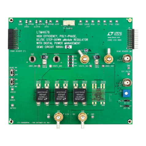
Tolomatic BCS10 Quick start quide

Tolomatic

Tolomatic BCS10 Quick start quide

Foxtech GS-75U manual

Foxtech

Foxtech GS-75U manual

GM International D1048S instruction manual
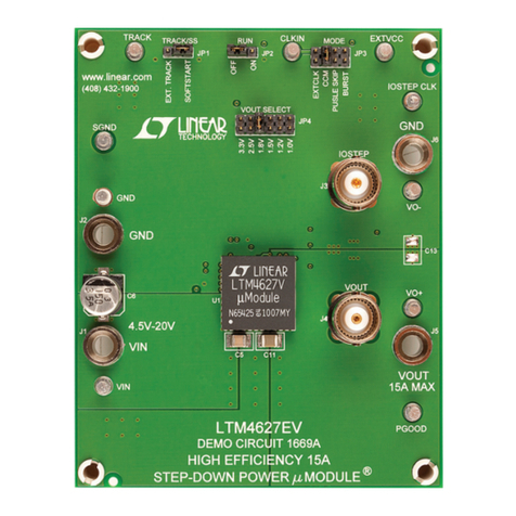
GM International

GM International D1048S instruction manual

Aqua Medic CO2 Regular manual

Aqua Medic

Aqua Medic CO2 Regular manual

WarmlyYours TH113-R-GA user guide

WarmlyYours

WarmlyYours TH113-R-GA user guide

WindowMaster WMS 306 technical information

WindowMaster

WindowMaster WMS 306 technical information

Co2meter RAD-0502 Operating manual instructions

Co2meter

Co2meter RAD-0502 Operating manual instructions

DekoLight 843025 manual

DekoLight

DekoLight 843025 manual

HANYOUNG NUX TPR-3SL instruction manual

HANYOUNG NUX

HANYOUNG NUX TPR-3SL instruction manual

HIMA HIMatrix F2 DO 8 01 manual

HIMA

HIMA HIMatrix F2 DO 8 01 manual

Siemens 7SR224 manual

Siemens

Siemens 7SR224 manual

Landi Renzo SE 81 SIC Installation and adjustment manual

Landi Renzo

Landi Renzo SE 81 SIC Installation and adjustment manual

GiBiDi PC200 Instructions for installation

GiBiDi

GiBiDi PC200 Instructions for installation

XPR Access WS4-1D quick start guide

XPR Access

XPR Access WS4-1D quick start guide

Delta C2000 Series user manual

Delta

Delta C2000 Series user manual

BLACKHAWK! USB100 quick start guide

BLACKHAWK!

BLACKHAWK! USB100 quick start guide

M-Elec AL-2 Series instruction manual

M-Elec

M-Elec AL-2 Series instruction manual

manuals.online logo
manuals.online logoBrands
  • About & Mission
  • Contact us
  • Privacy Policy
  • Terms and Conditions

Copyright 2025 Manuals.Online. All Rights Reserved.