QUICK START GUIDE FOR DEMONSTRATION CIRCUIT
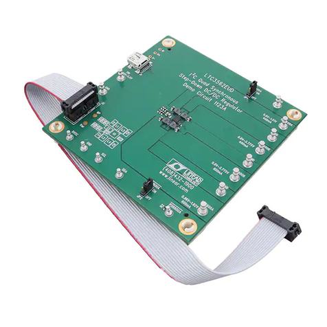
DC1296A
HIGH EFFICIENCY USB POWER MANAGER + DUAL BUCK + BUCK-BOOST
LTC3556EUFD
4
This form allows the feedback resistor divider net-
work on each regulator to be changed. The informa-
tion changed here, is saved, and is durable from
session to session. However, the factory values can
be recovered by pressing the “Restore defaults” but-
ton
QUICK START PROCEDURE
Complete the Quick Start Procedure outlined in the
Quick Start Guide for Demo Circuit 590 available
from the Linear Technology Web Site, prior to pro-
ceeding.
Refer to Figure 2 for the proper measurement
equipment setup and jumper settings and follow the
procedure below.
NOTE.
When measuring the input or output voltage ripple, care
must be taken to avoid a long ground lead on the oscilloscope
probe. Measure the input or output voltage ripple by touching the
probe tip directly across the VBUS or VOUT(x) and GND terminals.
See Figure 2 for proper scope probe technique.
1.
Set PS1 to 5.0V, and PS2 to 3.6V. Using the
LTC3556 GUI click on “5X Mode(500mA)”. In-
crease Ld2 to 200mA. Measure VOUT (VM6) ≈
3.68V, and I(VBUS) (AM1) ≈ 454mA.
VBUS is 5V, and can supply up to 500mA, or
2.5W. VOUT is being loaded at 200mA +
≈454mA (battery charge current) ≈654mA, so
VOUT will be 2.5W/0.654A ≈ 3.80V.
2.
Using the LTC3556 GUI click on “10X Mode(1A)”
under Average Input Current Limit Setting.
Measure VOUT (VM6) and IBAT. Measure VOUT
(VM6) ≈ 3.97V, and I(VBUS) (AM1) ≈ 510mA.
The input power limit is now higher than the
power load at VOUT, so VOUT rises to 3.97V ≈
(V(
BAT)
+ 0.35V).
3.
Set V(BAT) (PS2) to 2.5 V. Measure the battery
Current IBAT in trickle charge mode. Remove
the NTC jumper (JP1) and observe the CHRG
LED slow blinking rate (1.5Hz at 50% Duty Cy-
cle). Reinstall the NTC jumper (JP1). When
V(BAT) is below 2.85V (Typ.), the battery
charger attempts to trickle charge the battery up
above this threshold at ≈ I
CHARGE
/10 = 50mA.
When the battery charger detects a fault such as
the NTC pin signaling the battery is too cold or
too hot, it signals this by pulsing the
CHRG
pin at
a frequency and duty cycle that identifies the re-
ported fault.
4. Set the voltage on the BAT pin (PS2) to 4.21V.
Once the battery reaches the float voltage, the
battery charger switches from Constant Current
(CC) mode to Constant Voltage (CV) mode. The
purpose of Constant Voltage mode is keep the
battery “topped off” at the float voltage. If the
battery is unloaded, this current should be very
small.
5. With PS1 set at 5V, set the voltage on BAT (PS2)
to 3.6V. Set Ld1 to zero current and set ENALL
jumper (JP2) to “LO. Verify that the GOODALL
LED is lit. The GOODALL LED lights red when
one or all of the regulators is out of regulation, or
when all the regulators are off.
6.
Set the ENALL jumper (JP2) to “Hi” to turn on
VOUT1-VOUT3. Observe the start-up sequence
with an oscilloscope, measure VOUT1, VOUT2
and VOUT3 and observe the state of the
POWERGOOD ALL LED. The sequencing of
regulators VOUT1, 2, & 3 is controlled by the
state of the SEQ pin. The SEQ pin is a three state
input to the LTC3556, and three sequences are
programmable. There is no equivalent to the
SEQ pin in the I
2
C channel. SEQ is grounded so
the power supply sequence should be VOUT1
then VOUT2, then VOUT3.
7. Move the SEQ jumper (JP3) to “3->1->2”.
8. Set ENALL jumper (JP2) to “LO.
9.
Set the ENALL jumper (JP2) to “Hi” to turn on
VOUT1-VOUT3. Observe the start-up sequence
Downloaded from Arrow.com.Downloaded from Arrow.com.Downloaded from Arrow.com.Downloaded from Arrow.com.


