DEMO CIRCUIT 1418 QUICK START GUIDE LTC6604-X
1
DESCRIPTION
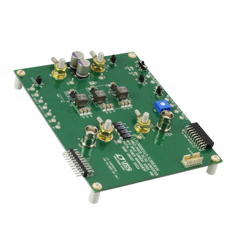
Demonstration circuit 1418 features the LT6604-XX se-
ries of a dual, matched, fully differential 4
th
order low-
pass filter
approximating a Chebyshev frequency re-
sponse
. The cutoff frequencies (Fc) of LT6604-XX are:
2.5MHz, 5MHz, 10MHz and 15MHz. (see Table 1).
The
LT6604-XX combines a lowpass filter with two fully
differential matched amplifiers for driving the differ-
ential inputs of a dual analog to Digital Converter
(ADC) and band-limiting the baseband signal of digi-
tal communications receiver.
Each LT6604-XX filter IC
requires only two external input resistors to set the fil-
ter’s differential gain.
A DC1418 board contains an
LT6604-XX configured with input resistors as two unity
gain differential amplifiers/lowpass filters.
Gains greater than one require changing the input resis-
tors to a lower value (refer to an LTC6604-XX data sheet
and the DC1418 schematic).
Gains greater than one require changing the input resis-
tors to a lower value (refer to an LTC6604-XX data sheet
and the DC1418 schematic).
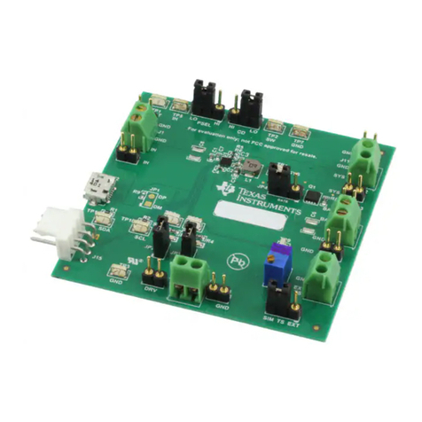
Connection to the differential input and output of a
DC1418 is through SMA connectors. On-board jumpers
configure the DC1418 for dual or single supply opera-
tion and internal or external output common (VOCM)
mode biasing. The differential input of a DC1418 is AC
coupled and can be configured for DC coupling by re-
placing shorting the input capacitors with zero ohms
surface-mount resistor jumpers. In addition, the
DC1418 has surface-mount pads to add input passive
components for input signal filtering and DC biasing.
Design
files for this circuit board are available.Design
files for this circuit board are available.
Call the LTC factory.Call the LTC factory.
, LTC and LT are registered trademarks of Linear Technology Corporation.
DEMO CIRCUIT 1418
QUICK START GUIDE
LTC6604-2.5, LTC6604-5, LTC6604-10 and LTC6604-15
Dual, Matched, Fully-Differential, Lowpass Filter
ASSEMBLY
DC1418A-A LTC6604-2.5, Fc = 2.5MHz
DC1418A-B
LTC6604-5, Fc = 5MHz
DC1418A-C LTC6604-10, Fc = 10MHz
DC1418A-D LTC6604-15, Fc = 15MHz
Table 1. The DC1418 Assemblies
Figure 1. The DC1418 Top Silk Screen
