Rohm BD868x0-EVK-302 User manual

1/6
QUICK START GUIDE
© 2022 ROHM Co., Ltd.
No. 65QS003E Rev.001
July 2022
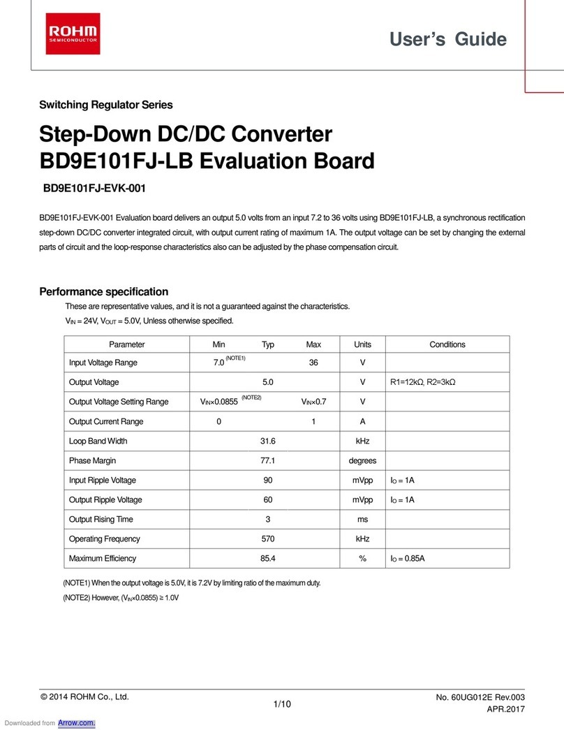
Evaluation board for PMIC BD868x0
BD868x0-EVK-302
This quick start guide will help you understand the connection, operating Instructions and important notices and warnings that need to be carefully
reviewed prior to use of the board (Figure 1).
The evaluation board has been designed to be used as a daughter board (DB) in combination with the main board PMIC-MB-EVK (MB) and the
software GUI interface. It can also be operated in stand-alone mode without GUI software. The BD868x0 contains 1 primary buck converter, 2
secondary buck converters and 1 secondary LDO that can be flexibly configured via factory OTP settings.
For further information please refer to the user guide (No. 65UG013E Rev.001).
Figure 1: Evaluation board
Important Notice
This evaluation board is intended for product evaluation in a research and development context only and is not intended for resale to end
consumers and it is not authorized for end customer or household use. This board may not comply with CE or similar standards (including, but not
limited to the EMC directive 2004/EC/108) and may not fulfil other requirements of the country it will be operated in by the user. The user shall ensure
that the evaluation board will be handled in a way that is compliant with all the standards and regulations in the country it will be operated in.

2/6
QUICK START GUIDE
© 2022 ROHM Co., Ltd.
No. 65QS003E Rev.001
July 2022
The evaluation board provided here has only been subjected to functional testing under typical load conditions. The design of this evaluation board
is tested by ROHM only as described in the user guide for this board. The design is not qualified in terms of safety requirements, manufacturing and
operation over the entire operating temperature range or lifetime.
This evaluation board may only be used by authorized personnel that is properly trained in recognizing and dealing with the dangers of
testing high voltage equipment and generally experimenting with high voltage circuits. Ensure you review this user guide as it contains
important safety warnings. At all times, follow the applicable safety rules for dealing with high voltages. Do not connect or disconnect any wires or
probes to the evaluation board, while it is connected to a power supply. Take care that capacitors on the board have discharged fully before touching
any part of the board. Always place the evaluation board under appropriate covers, such as in a Perspex box, to protect against accidental touching
of high voltage parts BEFORE applying a voltage supply to the board.
<High Voltage Safety Precautions>
◇ Read all safety precautions before use
Please note that this document covers only the BD868x0 evaluation board and its functions. For additional information,
please refer to the datasheet.
To ensure safe operation, please carefully read all precautions before
handling the evaluation board
Depending on the configuration of the board and voltages used,
Potentially lethal voltages may be generated.
Therefore, please make sure to read and observe all safety precautions described in
the red box below.
Before Use
[1] Verify that the parts/components are not damaged or missing (i.e. due to the drops).
[2] Check that there are no conductive foreign objects on the board.
[3] Be careful when performing soldering on the module and/or evaluation board to ensure
that solder splash does not occur.
[4] Check that there is no condensation or water droplets on the circuit board.
During Use
[5] Be careful to not allow conductive objects to come into contact with the board.
[6] Brief accidental contact or even bringing your hand close to the board may result
in discharge and lead to severe injury or death.
Therefore, DO NOT touch the board with your bare hands or bring them too close to
the board.

3/6
QUICK START GUIDE
BD868x0-EVK-302
© 2022 ROHM Co., Ltd.
No. 65QS003E Rev.001
July 2022
In addition, as mentioned above please exercise extreme caution when using conductive
tools such as tweezers and screwdrivers.
[7] If used under conditions beyond its rated voltage, it may cause defects such as short-
circuit or, depending on the circumstances, explosion or other permanent damages.
[8] Be sure to wear insulated gloves when handling is required during operation.
After Use
[9] The ROHM Evaluation Board contains the circuits which store the high voltage. Since it
stores the charges even after the connected power circuits are cut, please discharge the
electricity after using it, and please deal with it after confirming such electric discharge.
[10]Protect against electric shocks by wearing insulated gloves when handling.
This evaluation board is intended for use only in research and development facilities and should by handled only by qualified
personnel familiar with all safety and operating procedures.
We recommend carrying out operation in a safe environment that includes the use of high voltage signage at all entrances,
safety interlocks, and protective glasses.
Safety Precautions
Caution: This evaluation board may only be used by authorized personnel that is properly trained in
recognizing and dealing with the dangers of testing high voltage equipment and generally
experimenting with high voltage circuits. This board should only be used in a lab facility properly
equipped for the safe testing of power electronic systems at the relevant voltage levels. Failure to
comply may result in damage to equipment, personal injury or death.
Warning: The DC link and input voltage of this board may reach up to 900 V. Ensure that only
suitable high voltage differential probes are used to measure at this voltage. Failure to do so may
result in damage to equipment, personal injury or death.
Warning: This evaluation board contains DC bus capacitors which take time to discharge after
removal of the power supplies. Before working on the evaluation board wait at least six minutes after
deactivating all connected power supplies to ensure that the capacitors have discharged to a safe
level.
Warning: Ensure that you use only appropriate measurement equipment for the voltage levels
present on the board. Ensure not to ground live parts through unsuitable measurement probes or tie
different grounds together using passive probes. Suitable high voltage differential probes should be
used. Failure to do so may result in damage to equipment, personal injury or death.

4/6
QUICK START GUIDE
BD868x0-EVK-302
© 2022 ROHM Co., Ltd.
No. 65QS003E Rev.001
July 2022
Warning: Before disconnecting, connecting or reconnecting wires or measurement probes to the
board or before touching the board or performing any manipulations on the board ensure that all
external power is removed or disconnected from the board and at least six minutes have passed to
ensure the capacitors have discharged to a safe level and then ensure that the capacitor voltages
have dropped to a safe level.
Failure to do so may result in damage to equipment, personal injury or death.
Caution: The heatsink and some component surfaces on the evaluation board may become hot
during testing and remain hot for a certain time after turn-off. Take appropriate measures while
handling the board after use. Failure to do so may cause personal injury.
Caution: Incorrect connection of power supplies or loads can damage the board. Carefully review
the information in this document.

5/6
QUICK START GUIDE
BD868x0-EVK-302
© 2022 ROHM Co., Ltd.
No. 65QS003E Rev.001
July 2022
Board details
Below are the main specifications of the evaluation board:
Parameter
Description
Value
VIN1
Input voltage buck1
4.0 V to 18 V
VIN2, VIN3
Input voltage buck2,
buck3
3.0 V to 5 V
VOUT1
Output voltage buck1
3.7 V (Note 1)
VOUT2
Output voltage buck2
1.1 V (Note 1)
VOUT3
Output voltage buck3
1.8 V (Note 1)
IOUT1
Output current buck1
2 A
IOUT2
Output current buck2
1.2 A
IOUT3
Output current buck3
1 A
fSW
Switching frequency
2.25 MHz
VIN4
Input voltage LDO4
VOUT1
VOUT4
Output voltage LDO4
3.3 V (Note 1)
IOUT4
Output current LDO4
300 mA
TOPR
Operating
temperature
-40°C to 125°C
(Note 1) This value is set by OTP
Table 1: Specifications of evaluation board
Evaluation board overview
Locations of connectors in the evaluation board:
Figure 2: Top view of the evaluation boards (MB + DB)
Operating Instructions
The below procedures must be followed before beginning with
the tests.
1. Download and install the ROHM EVK GUI SW for your
Windows PC. The download link is Accelerometer
Evaluation Kit (rohm.com).After the installation, the
shortcut ROHM EVK GUI appears in the start-up menu
as well as shortcut on the desktop.
The configuration key is placed in the installation
directory of the local drive:
\\Documents\ROHM_EVK_v3\ROHM-EVK-
GUI\ConfigurationKeys
It is available on request from ROHM.
The CY8CKIT-059 comes preloaded with Rohm’s
custom firmware. The firmware can be found in the
installation directory:
\\Documents\ROHM_EVK_v3\ROHM-EVK-
Firmware\CY8CKIT-059
The guide for programming the RoKiX-CY8CKIT-059
firmware to the Cypress CY8CKIT-059 PSoC® 5LP
Prototyping Kit can be found in section 3.1 of the
ROHM EVK SW User’s Guide.
MCU only FW is available on request from ROHM.
2. Connect the BD868x0-EVK-302 board as follows:
- Plug BD868x0-EVK-302 board into PMIC-MB-EVK
board (MB).
- Connect +VIN (4V to 18V) and GND to main board
(MB).
- Optional: connect electronic load(s) to output(s).
Connect load between VO1 to GND, VO2 to GND etc.
3. Connect the CY8CKIT-059 to the PC using the
provided micro-USB cable to establish the connection
with the ROHM EVK GUI.
Note: With Windows 10, the operating system should
automatically use the correct driver. For earlier

6/6
QUICK START GUIDE
BD868x0-EVK-302
© 2022 ROHM Co., Ltd.
No. 65QS003E Rev.001
July 2022
Windows versions, please follow the driver installation
procedure in section 2 of the ROHM EVK SW User’s
Guide.
4. Start the ROHM EVK GUI software.
(1) The blue LED on CY8CKIT-059, the green
USB_ON_LED and the COM_ON_LED on the PMIC-
MB-EVK board light up, indicating that the system is
operational.
(2) Select the board name “BD868x0-EVK-302 DS2
(CRC ON, RnD)” in the drop-down menu on the top
right side of the GUI. See Figure 3.
Once done, you need to press the “Confirm board”
button. Now the field “EVK Connected” turns green.
(3) The BD868x0-EVK-302 now starts. All status flags
(WAROUTB and RSTOUTB) should be “High” now.
Additionally, the GUI shows the voltage level of each
output in the “ADC” box. See Figure 4.
5. The BD868x0-EVK-302 can operate without a PMIC-
MB-EVK board in stand-alone mode as well. Refer to
User Guide (No. 65UG013E Rev.001) for this.
6. The board can now be tested.
Figure 3: Choose appropriate EVK
Figure 4: status box (top), ADC box (bottom)
Table of contents
Other Rohm Motherboard manuals

Rohm
Rohm BD7695FJ User manual

Rohm
Rohm BD9E201FP4-Z User manual

Rohm
Rohm BD71837MWV Guide

Rohm
Rohm Shield-EVK-001 User manual

Rohm
Rohm BM1Z002FJ User manual

Rohm
Rohm RAGU V1.0 User manual

Rohm
Rohm BM92A56MWV-EVK-001 User manual

Rohm
Rohm KXTJ3-1057-EVK-002 User manual

Rohm
Rohm BD HC0 Series User guide

Rohm
Rohm BM3G007MUV-EVK-002 User manual

Rohm
Rohm BU94603 User manual

Rohm
Rohm BD9E200FP4-Z User manual
Rohm
Rohm LAPIS MK71050-03 User manual

Rohm
Rohm TO-247-4L User manual

Rohm
Rohm BD9A100MUV User manual

Rohm
Rohm BD7F100HFN-LB User manual
Rohm
Rohm TPPFCSIC-EVK-301 User manual

Rohm
Rohm Lapis ML610Q793 User manual

Rohm
Rohm BD63800MUF-EVK-002 User manual

Rohm
Rohm Lapis MK715 1 Evaluation Kit Mini Plus... User manual