Linear 2GIG-TAKE-345 User manual

©2013 2GIG by Linear Corporation. All Rights Reserved. 1
Super Switch (Takeover Module)
INSTALL INSTRUCTIONS
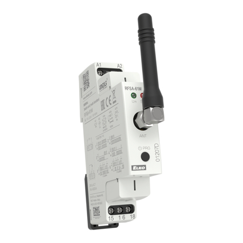
The2GIG‐TAKE‐345SuperSwitchis2GIG’swirelesstakeovermodule.Thisunitwas
designedtoconvert8hardwiredzonesintoeightwirelesszones,makeinstallation
simple,andworkwithexisting12‐voltcontrolpanels.Themoduleistobemounted
nexttotheexistingControlPanelwherethehardwiredzonesareconnected.Allof
thezonesontheSuperSwitchactassupervisedwirelesszones.
IMPORTANT: Ifthecontrolpanelhasbeenremovedthena12‐voltpower
supplywithbatterybackupisrequired(notsupplied).
Box Contents
•TakeoverModule
•MountingPlate
•2Phillipsheadscrews
•2Plasticdrywallanchors
PROGRAMMING
Thefollowingstepsareguidelinesforprogramming(learning)theSuperSwitchinto
the2GIGControlPanel.Scrollbetweenoponsusingthe←and→arrows.Moveto
thepreviousornextpromptbypressingthe↑and↓arrows.
1SelectRFsensor#(01to48).AssigntheTakeoverModuletoanewzone.
(Terminals1‐8)
2SelectRFsensortype.
(01)Exit/Entry
(02)Exit/Entry
(03)Perimeter
(04)InteriorFollower
3SelectRFequipmenttype.
4SelectRFsensorequipmentcode.Enter0873forthe2GIG‐TAKE‐345module.
5EnterRFsensorserialnumber(7digits).
ManualEntry:Typeinthelast7‐digitserialnumberthatendsin“1”(XXX‐
XXXX1)thatisfoundonthebackoftheSuperSwitch(thisistheserialnumber
forZone1).
Foreachadditionalzone,addadigittotheendoftheserialnumber.For
example,Zone(terminal)2willbe(XXX‐XXX2)
AutoEntry:WiththepanelinLearn‐inmode(pressShiftthenLearn)tripthe
zonethatyouwanttolearnin.ThecorrectTXIDshouldappear.Acceptthe
correctTXIDbypressingok.
Remembertopressthe↓arrowtocontinuethroughthe
systemconfigurationprompts.
6SelectRFsensorequipmentage.
(0)new(productisnew)
7SelectRFsensorloopnumber(1).
(1)1
8SelectRFsensor1dialerdelay.
(0)disabled
(1)enabled
9ConstructRFsensordescriptor.PressInsertthenpressanynumberbetween
002and255toaddaword.Forexample,ifyouwantedtonamethisTake over
Moduleas“WirelessSensorTool,”pressInsertthenpress252forWIRELESS.
PressInsertthenpress191forSENSOR.PressInsertthenpress233forTOOL.
10 SelectRFsensorreports(0to1).
(0)disabled(sensordoesNOTreporttothecentralstation)
(1)enabled(sensorreportstothecentralstation)
11 SelectRFsensorsupervised(0to1).
(0)disabled(sensordoesNOTreportlossofsupervisionorlowbattery)
(1)enabled(sensorreportslossofsupervisionorlowbattery)
12 SelectRFsensorchime(0to13).
(0)disabled(panelwillnotchimewhensensorisactivated)
(1‐13)enabled(selectsavoiceand/orchimetosoundwhensensorisactivated)
13 Toprogramanothersensor,clicknext.
14 Toexitprogramming,clickskipthenendandexit.Uponexit,
thepaneltakesafewsecondstoreset.
FORUL/ETLListedInstallationsusethefollowingequipment:
Altronix(TM)powersupply/chargermodel#AL100ULwithan
Altronix(TM)plug‐intransformer,model#TP1620andaPower
SonicModelPS‐121212Volt1.4AmpHourrechargeablesealed
leadacidbatteryorequivalent.See"UsingtheAltronixPowerSupply"onpage3.
Monitoring the Battery
TheSuperSwitchwilloperateontheconnectedbatteryifthereisanAC
failure,unlessthebatteryisnotcapableofsupplyingenoughpower.
TheSuperSwitchmonitorsthebatterytoensureitisoperational.When
theSuperSwitchdetectsabatteryvoltagebelownormallevelfora
periodoftime,theSuperSwitchreportsalowbatteryforeachzone(if
programmedinstep11underProgramming).
Testing the Battery Voltage
Ifyougeta“LowBattery”Indicator,dothefollowing:
1Testthebattery’svoltagewithavoltreadertoensurethat12voltsarepassing
throughtheswitch.
2Ifthebatteryisfine,removepowerfromtheSuperSwitch(disconnectbattery
andAUXpowerterminal2).
3RewiretheSuperSwitchbyconnectingthebatteryfirst.
4AftertheSuperSwitchispoweredbythebattery,connectAUXpowerto
terminal2ontheSuperSwitch.
5RemovepowerfromtheControlPanelandthenpoweruptheControlPanel.If
everythingisconnectedcorrectly,the“LowBattery”indicatorshoulddisappear.
IMPORTANT: Ifthereisnoexistingsystem,thenuseyourownpowersupply
andgroupallofthegroundwirestogetherandconnectthemtothe
groundportontheSuperSwitch.
INSTALLING AND MOUNTING
•ScrewthemountingbrackettoawallandattachtheSuperSwitch.To release
thebracket,pulluponthetabandslidethebracketdown.Mountthebracket
with2screws.MounttheSuperSwitchinRFrangeoftheControlPanel.
To Wire Super Switch with an Existing Power Source
*SeeFigure1onnextpage
1RemoveACpowerfromexistingwiredpanel.
2Removeleadsfrombatteryonexistingwiredpanel.
3Withpowerremoved,wirethezonestotheSuperSwitch.Te rmina ls3‐10are
markedasZones1‐8ontheSuperSwitchandarewherethezonesare
connected.Forexample,towirezone1ontheSuperSwitchtakethepositiveor
HIsideofthezoneofftheexistingpanelandplaceitinterminal3/Zone1on
theSuperSwitch.LeavethenegativesideortheLO(GND)sideofthezone
wiredtotheexistingControlPanel.
4RepeatthisprocedureforallzonestobeconnectedtotheSuperSwitch.
TIP: AnoptionistoremoveallLOwiresfromexistingpanel,groupthem
together,andconnectthemtothegroundport.
WARNING: THISISNOTFORUSEINAUL/ETLLISTEDINSTALLATION.
To Wire Super Switch without an Existing Power Source
See"UsingExistingSystemWiring"onpage3.
*SeeFigure2onnextpage
IMPORTANT: BeforeconnectingpowertotheSuperSwitch,wirethezones
totheSuperSwitch.Term ina ls 3‐10aremarkedasZones1‐8ontheSuper
Switch.Forexample,towirezone1ontheSuperSwitchtakethepositive
orHIsideofthezoneplaceitinterminal3/Zone1ontheSuperSwitch.
1RepeataboveforallzonestobeconnectedtotheSuperSwitch.
2GroupallLO/(GND)wirestogetherandconnectthemtoterminal1/G(GND
PortoftheSuperSwitch.
WARNING: DONOTPLUGTHEPOWERSUPPLY/CHARGERPLUG‐IN
TRANSFORMERINTOANOUTLETCONTROLLEDBYASWITCH.
Powering the Super Switch and Other Devices
1TheSuperSwitchhastwowiresattachedRED(+)andBLACK(‐).Connectthe
Redwiretotheredterminalandtheblackwiretotheblackterminalonthe
existingControlPanel’sbattery.
2ConnectthewiresfromtheexistingControlPanelforthebatteryintothe
spadeslugsontopofthewiresfromtheSuperSwitchthatisnowconnectedto
thebattery.
3IFUSINGANEXISTINGPOWERSOURCE:WiretheexistingpanelsAUXpower
outtoterminal2/12VportontheSuperSwitch.IfyouareusingtheSuper
SwitchwithPIRs,GlassBreakDetectors,orotherdevicesthatneedpower,then
theymustreceivepowerfromtheAUXpowerontheexistingControlPanel.
ReconnectACpowertoexistingpanel.
NOTE: RemoveallotherdeviceswiredtoAUXpowerontheexistingControl
Panel(suchaskeypadsoranyotherunuseddevicesrequiringpower).
WARNING: THISISNOTFORUSEINAUL/ETLLISTEDINSTALLATION.

2©2013 2GIG by Linear Corporation. All Rights Reserved.
Figures 1 and 2

©2013 2GIG by Linear Corporation. All Rights Reserved. 3
Using Existing System Wiring
Using the Altronix Power Supply

4©2013 2GIG by Linear Corporation. All Rights Reserved.
Important to Remember
1AllofthezonesontheSuperSwitchare“normallyclosed”zones.
2Themaximumloopresistancecannotexceed3Kohms(Iftheloopresistance
exceeds3Kohmsandtheexistingpanelusedendoflineresistance,thenthe
endoflineresistormayberemoved).
3Differentcontrolpanelshavedifferentterminalsforeachzoneandauxpower.
Pleaserefertothewiringdiagramsthatcamewiththeexistingpanels.For
example,theHIsideofZone1—Zone8ona“Vista”panelistypicallyterminals
8,11,12,14,15,17,18,and20.AUXpositiveistypicallyterminal5ona“Vista”
panel.
WARNING: TheSuperSwitchCANNOTbeusedtomonitoranytypeoffire
orCODetectionZones.
Specifications
Regulatory Compliance
ThisdevicecomplieswithPart15oftheFCC'sRules.Operationis
subjecttothefollowingtwoconditions:
1.Thisdevicemaynotcauseharmfulinterference,and
2.Thisdevicemustacceptanyinterferencereceived,including
interferencethatmaycauseundesiredoperation.
Thisequipmenthasbeentestedandfoundtocomplywiththelimits
foraClassBdigitaldevice,pursuanttoPart15oftheFCCRules.These
limitsaredesignedtoprovidereasonableprotectionagainstharmful
interferenceinaresidentialinstallation.
Thisequipmentgenerates,usesandcanradiateradiofrequency
energyand,ifnotinstalledandusedinaccordancewiththe
instructions,maycauseharmfulinterferencetoradio
communications.However,thereisnoguaranteethatinterference
willnotoccurinaparticularinstallation.Ifthisequipmentdoescause
harmfulinterferencetoradioortelevisionreception,whichcanbe
determinedbyturningtheequipmentoffandon,theuseris
encouragedtotrytocorrecttheinterferencebyoneormoreofthe
followingmeasures:
•Reorientorrelocatethereceivingantenna.
•Increasetheseparationbetweentheequipmentandreceiver.
•Connecttheequipmentintoanoutletonacircuitdifferentfrom
thattowhichthereceiverisconnected.
•Consultthedealeroranexperiencedradio/TVtechnicianforhelp.
ThisproductcomplieswithFCCradiationexposurelimitsforan
uncontrolledenvironment.Avoidoperatingthisproductatadistance
lessthan20cmfromuser.
Caution:Anychangedormodificationsnotexpresslyapprovedbythe
partyresponsibleforcompliancecouldvoidtheuser'sauthorityto
operatethisequipment.
Limited Warranty
This2GIGTechnologiesproductiswarrantedagainstdefectsin
materialandworkmanshipfor2years.Thiswarrantyextendsonlyto
wholesalecustomerswhobuydirectfrom2GIGTech nologiesor
through2GIGTechnologies’normaldistributionchannels.2GIG
Technologiesdoesnotwarrantthisproducttoconsumers.Consumers
shouldinquirefromtheirsellingdealerastothenatureofthedealer’s
warranty,ifany.
Therearenoobligationsorliabilitiesonthepartof2GIGTechnologies
forconsequentialdamagesarisingoutoforinconnectionwithuseor
performanceofthisproductorotherindirectdamageswithrespectto
lossofproperty,revenue,orprofit,orcostofremoval,installation,or
reinstallation.Allimpliedwarrantiesforfunctionality,arevalidonly
untilthewarrantyexpires.This2GIGTechnologiesWarrantyisinlieu
ofallotherwarrantiesexpressedorimplied.
FortechnicalsupportintheUSAandCanada:
855‐2GIG‐TECH(855‐244‐4832)
Email:[email protected]
Internet:dealer.2gig.com
Visitwebsitefortechnicalsupporthoursofoperation
FortechnicalsupportoutsideoftheUSAandCanada:
Contactyourregionaldistributor
Visitdealer.2gig.comforalistofdistributorsinyourregion
PN:IPM‐1047‐02Rev.D
WirelessSignalRange 350ft,openair,with2GIGWirelessControlPanel
CodeOutputs Foreachof8serializedzones:Fault;Restore;
Tamper;LowBattery
TransmitterFrequency 345.000MHz(crystalcontrolled)
TransmitterFrequency
Tolera nce
±15kHz
TransmitterBandwidth 24kHz
ModulationTypeAmplitudeShiftKeying‐On/OffKeying(ASK‐OOK)
UniqueIDCodes Overonemilliondifferentcodecombinations
SupervisoryInterval 70minutes
PeakFieldStrength Typical50,000uV/mat3m
SensorDimensions(LxWxH) 3.54x2.56x1.13in.(9.0x6.5x2.9cm)
Weight(includingbracket) 2.85oz.(80.8g)
HousingMaterial ABSplastic
Color White
OperatingTem peratureLimits 32°to120°F(0°to49°C)
RelativeHumidity 5‐95%Non‐Condensing
OperatingVoltage 9‐16voltsDC,50mA
IncludedAccessories Mountingplate,2Phillip’sheadscrews,2plastic
drywallanchors
This manual suits for next models
2
Other Linear Switch manuals
Linear
Linear 300 Series User manual

Linear
Linear LTC7860 Quick setup guide

Linear
Linear HDMI-MX-4x4 User manual

Linear
Linear LTC7000 Quick setup guide
Linear
Linear HDMI-SW-4X2M User manual

Linear
Linear DA-506BID Operating instructions

Linear
Linear HDMI-SW-2X2M User manual
Linear
Linear HDMI-SW-3X1 User manual
Popular Switch manuals by other brands
Agilent Technologies
Agilent Technologies 3488A Service note

schmersal
schmersal AZ201-I2-CC-T-1P2P Operation and assembly instructions

ZyXEL Communications
ZyXEL Communications Dimension GS-2024 quick start guide
Kramer
Kramer VP-445 user manual
Panduit
Panduit ATLONA Omega AT-OME-MH21 manual
Cisco
Cisco Meraki MS210 Series installation guide
