Link LK-EXP07PR User manual

LINK
INSTALLATION MANUAL
LK-EXPO7PR
FORD EXPEDITION
2007-2017
PASSENGER SIDE FRONT
FULLY LOADED SEAT
14
9
11
4
13 8
2
10
7
1
12
16
2
65
3
17
21
15
19
20
18
22
1 of 4
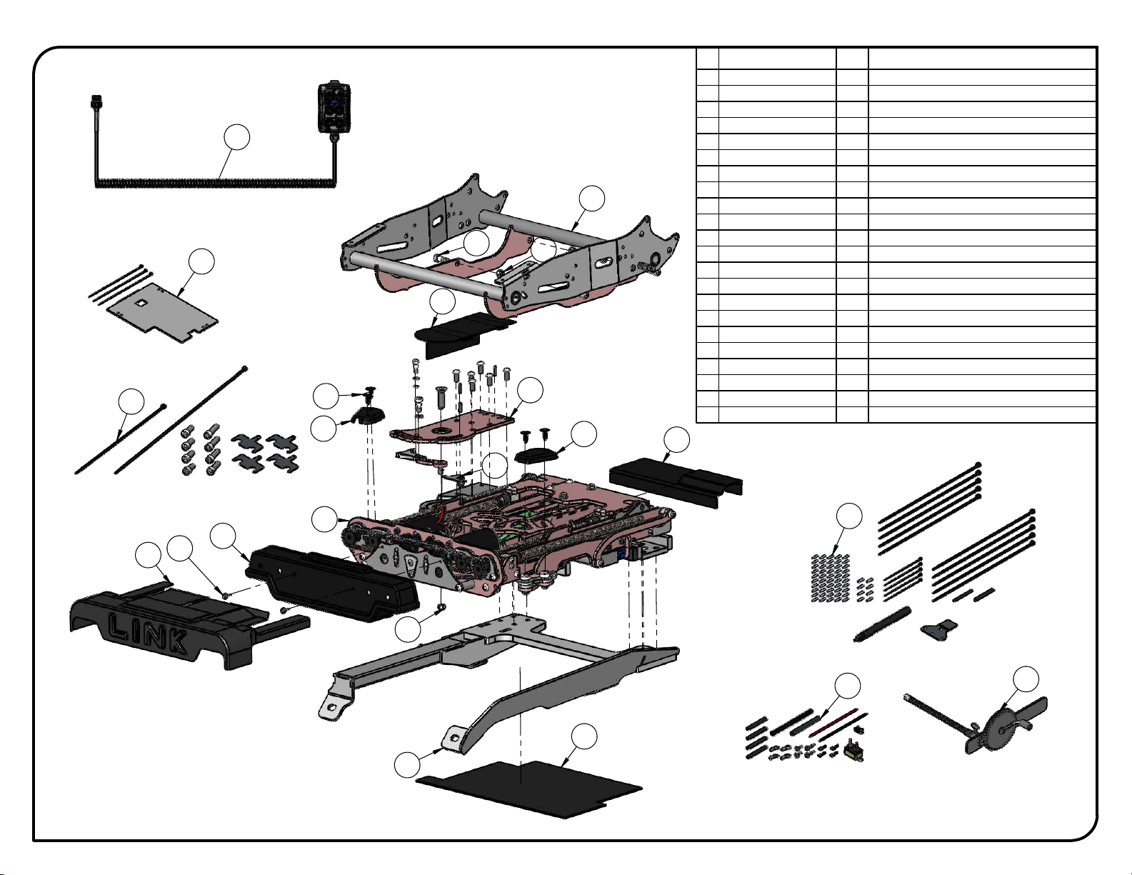
ITEM
PART NUMBER
QTY
DESCRIPTION
1
LK000R-02
1
Long Model LINK -Right-
2
LK-UNI-009R
1
009 Assembly Top Bearing Plate -Right-
3
LK-EXP07R-03
1
Seat Adapter -Right-
4
L-LK912
1
Communication Cable Support
5
PRD 333-107
4
Nylon Insert Locknut 5/16-18
6
PRD 339-136P
4
Socket Shoulder Screw Zinc Plated 3/8 x 1/2 x 5/16-18
THD
7
LK710B
1
Chain Covert -Black-
8
PRD 110-106
2
Round washer head tapping screw #8 x 3/4
9
LK750RB
1
Pivot Cover -Right- Black
10
LK730RB
1
Inside Cover -Right- Black
11
LK731RB
1
Outside Cover -Right- Black
12
PRD 251-177
4
Trim Panel Clip Ø1/4'' x 3/4'' Black
13
LK700B
1
Link Covert -Black-
14
LK720RB
1
Pivot Motor Cover -Right- Black
15
LK960
1
LINK Wired Control
16
LK-EXP07R-01
1
Floor Adapter -Right-
17
LK-EXP07RB-05
1
Floor Rear Cover -Right- Black
18
LK-EXP07R-06
1
Seat Fan Base -Right-
19
LK-EXP07R-BK
1
Bolt Kit -Right-
20
LK-EXP07R-AB
1
Air Bag LINK Kit -Right-
21
EW-CK-00
1
12V Power Supply Wiring Kit
22
LK-UNI-650
1
Manual Backup Tool Kit
LK-EXP07R
ADAPT SOLUTIONS
|[email protected]|866.641.0419|418.889.9838 fax
PART NUMBER
LINK Ford Expedition 2007 - 2016 -Right-
DESCRIPTION
LINK FORD EXPEDITION 2007 - 2016

13
11
14
12
6
2
3
4
8
10
1
9
9
7
5
2 of 4
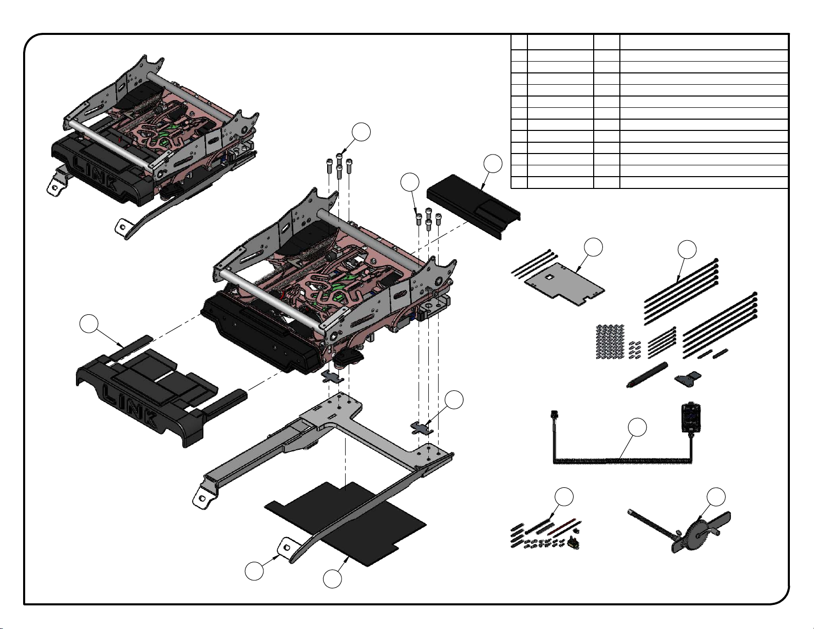
ITEM
PART NUMBER
QTY
DESCRIPTION
1
LK000R-02
1
Long Model LINK -Right-
2
LK-UNI-309R
1
009 Top Bearing Plate -Right-
3
LK-UNI-409
1
409 Cam Pusher
4
LK-UNI-509R
1
509R Pusher Frame -Right-
5
PRD 192-135
1
Spring Tension Pin 5/32 x 3/4
6
PRD 192-141
1
Spring Tensions Pin 3/16 x 3/4
7
PRD 192-151
1
Spring Tension Pin 1/4 x 3/4
8
PRD 333-107
1
Nylon Insert Locknut 5/16-18
9
PRD 337-213P
3
Button head socket cap screw Zinc Plated 5/16-18 x 3/4
10
PRD 339-116P
1
Socket Shoulder Screw Zinc Plated 5/16 x 1/2 x 1/4-20 THD
11
PRD 339-135P
1
Socket Shoulder Screw Zinc Plated 3/8 x 3/8 x 5/16-18 THD
12
SN 654-006
1
Nylon Spacer id .317" od .500"
13
SN 654-007
1
Nylon Spacer id .375" od .625"
14
SN 681-129
1
Wave Disc Spring 0.325 id x 0.546 od x 0.007 thickness
LK-EXP07R
ADAPT SOLUTIONS
|[email protected]|866.641.0419|418.889.9838 fax
PART NUMBER
LINK Ford Expedition 2007 - 2016 -Right-
DESCRIPTION
LINK FORD EXPEDITION 2007 - 2016

4
10 9
6
3
72
8
5
1
3 of 4
ITEM
PART NUMBER
QTY
DESCRIPTION
1
LK-EXP07R-03
1
Seat Adapter -Right-
2
LK710B
1
Chain Covert -Black-
3
LK730RB
1
Inside Cover -Right- Black
4
LK731RB
1
Outside Cover -Right- Black
5
LK750RB
1
Pivot Cover -Right- Black
6
L-LK912
1
Communication Cable Support
7
PRD 110-106
2
Round washer head tapping screw #8 x 3/4
8
PRD 251-177
4
Trim Panel Clip Ø1/4'' x 3/4'' Black
9
PRD 333-107
4
Nylon Insert Locknut 5/16-18
10
PRD 339-136P
4
Socket Shoulder Screw Zinc Plated 3/8 x 1/2 x 5/16-18 THD
LK-EXP07R
ADAPT SOLUTIONS
|[email protected]|866.641.0419|418.889.9838 fax
PART NUMBER
LINK Ford Expedition 2007 - 2016 -Right-
DESCRIPTION
LINK FORD EXPEDITION 2007 - 2016
7
6
1
4 of 4
2
12
11
5
8
9
4
3
10
ITEM
PART NUMBER
QTY
DESCRIPTION
1
LK-EXP07R-01
1
Floor Adapter -Right-
2
LK-EXP07RB-05
1
Floor Rear Cover -Right- Black
3
LK-EXP07R-06
1
Seat Fan Base -Right-
4
LK-EXP07R-AB
1
Air Bag LINK Kit -Right-
5
L-LK-UNI-250
2
Fixing Spacer
6
LK700B
1
Link Covert -Black-
7
LK720RB
1
Pivot Motor Cover -Right- Black
8
LK960
1
LINK Wired Control
9
EW-CK-00
1
12V Power Supply Wiring Kit
10
LK-UNI-650
1
Manual Backup Tool Kit
11
PRD 332-164P
4
Socket Head Cap Screw Zinc Plated 3/8-16 x 7/8
12
PRD 332-166P
4
Socket Head Cap Screw Zinc Plated 3/8-16 x 1 1/4
LK-EXP07R
ADAPT SOLUTIONS
|[email protected]|866.641.0419|418.889.9838 fax
PART NUMBER
LINK Ford Expedition 2007 - 2016 -Right-
DESCRIPTION
LINK FORD EXPEDITION 2007 - 2016
*ESTIMATED he ig ht a nd insta lla tio n time (b a se mo d e l).
HIG HER TRIM LEVELS REQ UIRED A DDITIO NAL INSTALLA TIO N TIME.
ADAPT SOLUTIONS
05-2020
LINK REFERENCES
LK- EXP07R
Se a t he ig ht: 3/ 8 inc h hig he r tha n O EM
*Transfer height: 19”|Ave ra g e insta ll: 6- 8 hrs.
O EM shro ud s must b e trim me d .
Se a t a d justm e nts|FRO NT: 2 ¾ inc h le ss tha n O EM|BACK:1” mo re tha n O EM
Ple ase sp e c ify if e q uippe d with p o we re d se ats.
Ke e p ve nte d se a ts.
Insta lla tio n time va rie s d e p e nd ing o n O EM fe a ture s inte g ra te d in the se a t.
O EM wire ha rne ss m ust b e c ut a nd e xte nd e d unde r se a t.
Exte nsive wire ha rne ss wo rk re quire d o n fully e q uip pe d m ode ls. (Add tim e )
Fully e q uipp e d m o de l ha s la rg e m e m o ry b o x m o dule .
A dditio na l tim e re q uire d fo r fa ste ning m e m o ry b o x to the flo o r.
O EM wire ha rne ss must be c ut a nd e xte nde d unde r se a t.
O EM shro uds m ust b e trim m e d .
Ke e p ve nte d se a ts.

LINK 2007-2017 FORD EXPEDITION PASSENGER FRONT. p. 2
WARNINGS
PLEASE REVIEW BEFORE STARTING THE INSTALLATION
Look through the entire manual to understand the installation process.
Watch the tutorial videos that are found on the tablet.
During the installation use the ‘BYPASS’ mode to move the LINK.
Do not use the pendant or ‘PENDANT’ mode until you have reset the home position.
The LINK is designed to ALWAYS use the original seat. The biggest challenge this will present for the installer will
be extending the vehicle’s original seat wire harness, as this MUST be done. The general process does not vary, but
the exact steps will vary due to the trim level, the model and seat options from the vehicle manufacturer. Keeping
this in mind, we have made an effort to clearly describe the process required in this manual. However, it is possible
that the pictures in this manual do not match exactly the specific vehicle you are working on.
SEAT WIRING EXTENSION PROCESS
The wiring must be extended 80 inches. This extension is placed near the seat connectors that are under the seat.
The extension (80 inches) then passes under the LINK and loops around the back of the OEM seat –allowing the
seat and the LINK to travel in and out of the vehicle. Depending on the make, model and seat options, there are
components that must be disconnected, bypassed and/or relocated. On vehicle models with a seat position
memory function, the forward/backward, tilt and height adjustments as well as seat memory are replaced by the
LINK. However, the seat recline function is retained. (EXAMPLE: In the Ford F150, 2009-2014 model; the seat
height, tilt, forward and backward adjustment motors are disconnected and removed with the seat frame, but the
recline motor is retained. The control and memory box are relocated to the floor under the seat, next to the seat
connectors. The seat position sensor is also relocated to the floor under the seat. The wiring harness is then
extended from this point under the seat.)
PLEASE NOTE: If the ignition is turned on while extending a wire harness that includes airbags, this may cause the
airbag light to stay on following the installation.
ADAPT SOLUTIONS CANNOT BE HELD RESPONSIBLE FOR FAULTY WIRE EXTENSIONS.
Please use caution during the installation.
ANDROID TABLET –LINK I.T. SOFTWARE
If this is your first installation of a LINK, you will have also purchased an Android tablet that is required for the
installation and maintenance of the LINK product. This tablet will have the LINK IT software already installed.
We have prepared quick, easy and to the point tutorial videos imbedded into the software. Take a moment and
watch the video that shows all the features of the tablet. To do this, open the LINK IT app and tap on ‘INFO’.
Make sure your volume is turned up and tap on App-101. The video will start automatically.
REDUCED POWER MODE
A safeguard is integrated in the LINK system. Following any changes to the preset or sequence of the LINK, the
unit will enter a reduced power mode. This is to allow you to visually inspect the movements of the LINK to ensure
it is not damaging the vehicle or itself during its first cycle. On the tablet, a yellow bar will appear at the top of the
screen to indicate you are in reduced power mode. To exit, simply run the LINK a full cycle. NOTE:It is possible
that the LINK will stop during this cycle as power is reduced. Visually confirm nothing is impeding the movements
and then simply press the IN or OUT button again to continue the cycle. During the installation, if the 12V power is
removed and replaced at the same time as the 9V battery (LINK memory back up) is unplugged or fully drained,
the LINK will enter reduced power mode. Simply run a full cycle to exit. PLEASE NOTE: You will find an explanation
of this mode on a YELLOW tag attached to the hand pendant. Please explain the functions of the reduced power
mode to the LINK user (your client).
For technical support call 866.641.0419 or email tech@adaptsolutions.com
Please have the serial number of the unit on hand before placing your call.

LINK 2007-2017 FORD EXPEDITION PASSENGER FRONT. p. 3
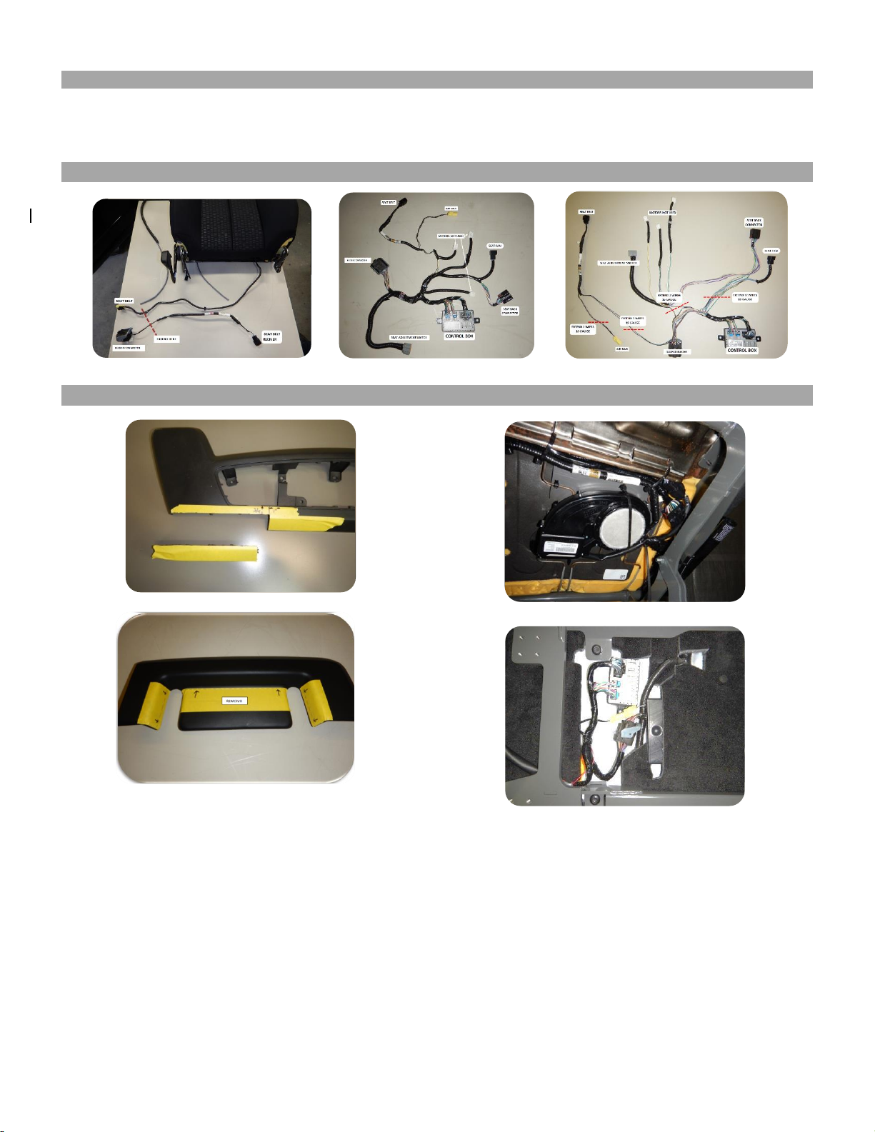
1. Remove the passenger side OEM seat and place on a workbench and remove all the plastic shrouds.
Remove and keep the OEM seat bolts to install the LINK floor adapters.
LINK 2007-2017 FORD EXPEDITION PASSENGER FRONT. p. 4
2. Disconnect the seat base seat back connectors, and remove the seat back.
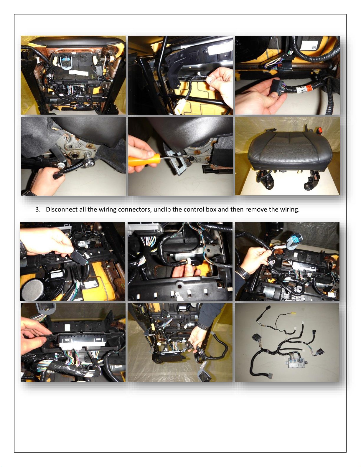
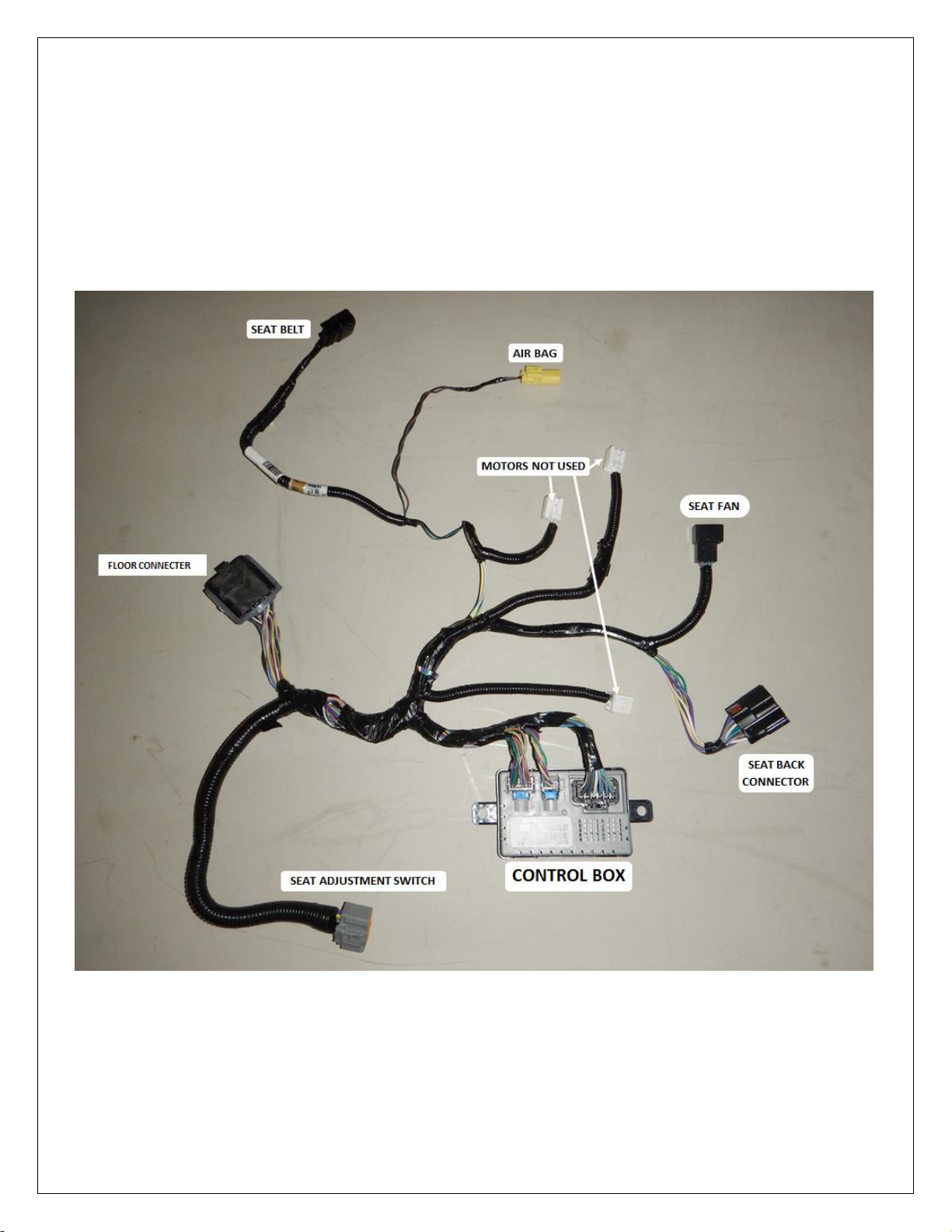
3. Disconnect all the wiring connectors, unclip the control box and then remove the wiring.

LINK 2007-2017 FORD EXPEDITION PASSENGER FRONT. p. 5
4. Remove the seat cushion from the seat frame.
5. Remove the seat belt receiver and pre-tensioner.

LINK 2007-2017 FORD EXPEDITION PASSENGER FRONT. p. 6
6. Unclip the seat base fan from the seat cushion supports.
7. Remove the seat base cushion supports.
8. Remove the seat pan from the seat base. Also, remove the seat trim support bracket from the seat
base.
LINK 2007-2017 FORD EXPEDITION PASSENGER FRONT. p. 7
9. The wiring harness extension can now be made using the provided multibrand cable. Extend the
OEM wire harness with the provided connectors and 18 gauge multi strand extension. Start the
extension six (6) inches from the floor connector. For best results, extend one wire at a time. Test
continuity of each wire through the extension to avoid errors. (If you wish to keep a record of your
wire extensions for reference, you will find a lined sheet at the very end of this manual for that
purpose.)
WIRING BEFORE EXTENTION

LINK 2007-2017 FORD EXPEDITION PASSENGER FRONT. p. 8
WIRING OPEN FOR EXTENTION
The wiring will have to be opened up to gain access to the wires to be extended.
The control box is extended along with the air bag and floor connector and relocated to the floor.
The seat back air bag connector is also extended at the same time.
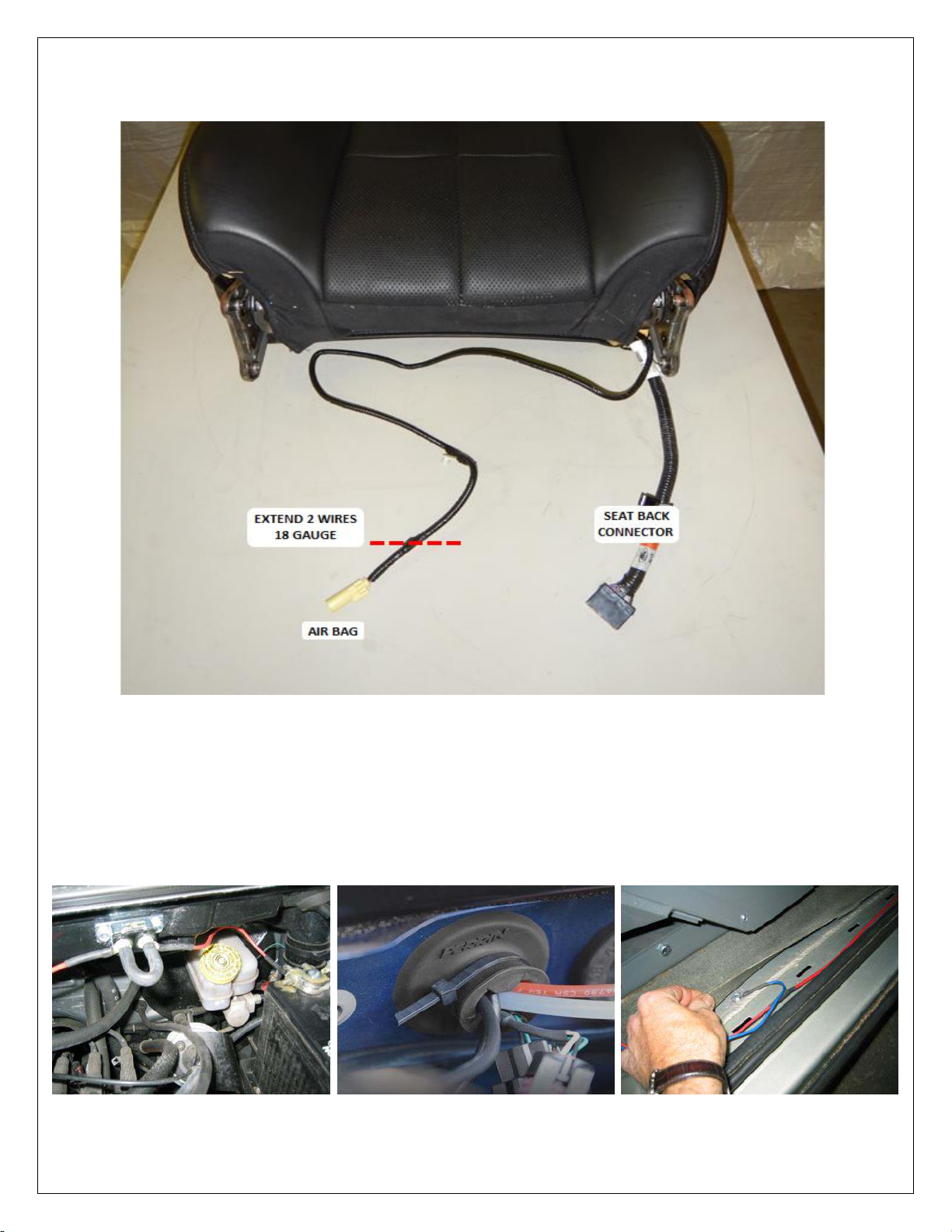
LINK 2007-2017 FORD EXPEDITION PASSENGER FRONT. p. 9
SEAT BACK
10. Run the power from the battery to the LINK. To do this, thread the red power cable (+) under the
doorstep moulding and through the firewall. Make sure you pass through a grommet in the firewall
to prevent the cable from chaffing. Install the circuit breaker near the battery and then connect the
battery to the circuit breaker. Attach the black ground wire (-) to the vehicle’s frame, under the
doorstep moulding using a self-tapping screw. Locate a spot where the sheet metal is doubled-up to
ensure a proper ground.

LINK 2007-2017 FORD EXPEDITION PASSENGER FRONT. p. 10
11. Cut and fold back the rear part of the floor carpet. Connect and position the wiring connectors and
control box on the floor, then Install the LINK floor adapter # LK-EXP07R-01 using the OEM bolts.
12. Install the provided plastic cover# LK-EXP07RB-05.
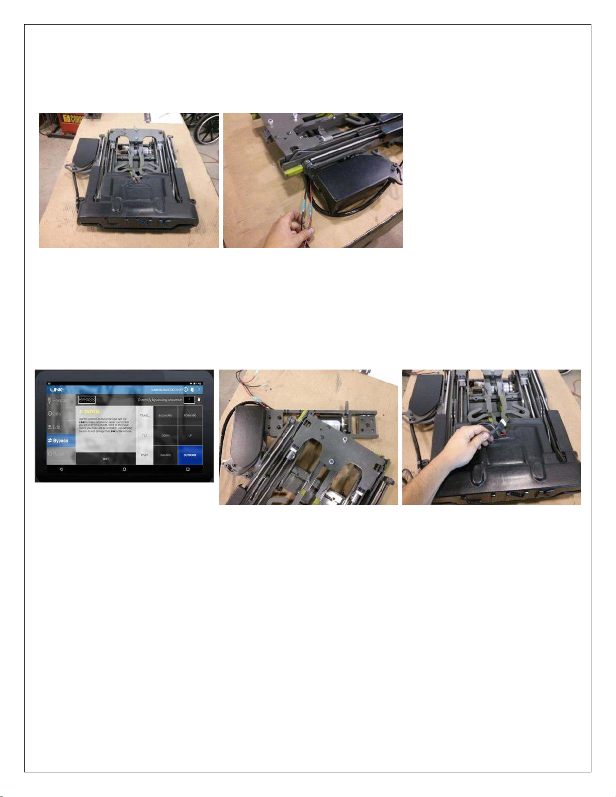
LINK 2007-2017 FORD EXPEDITION PASSENGER FRONT. p. 11
13. Remove the LINK from the shipping box and set it on a table or workbench. Connect auxiliary 12V
power to the LINK. The LINK will ‘beep’ during the installation. (See LINK Audible Warnings
chart for further references.)
14. Next, connect the LINK to the Android tablet via Bluetooth. Connect the Bluetooth module (small,
blue and white, 4 pronged connector) to the LINK pendant plug. Make sure the tablet and LINK
are connected. (Detailed explanations are found in the video tutorial, under INFO.) Using the
LINK IT application, open ‘BYPASS’. Press the ‘PIVOT OUTWARD’ button to move the LINK out
just enough to see the eight (8) bolt holes.
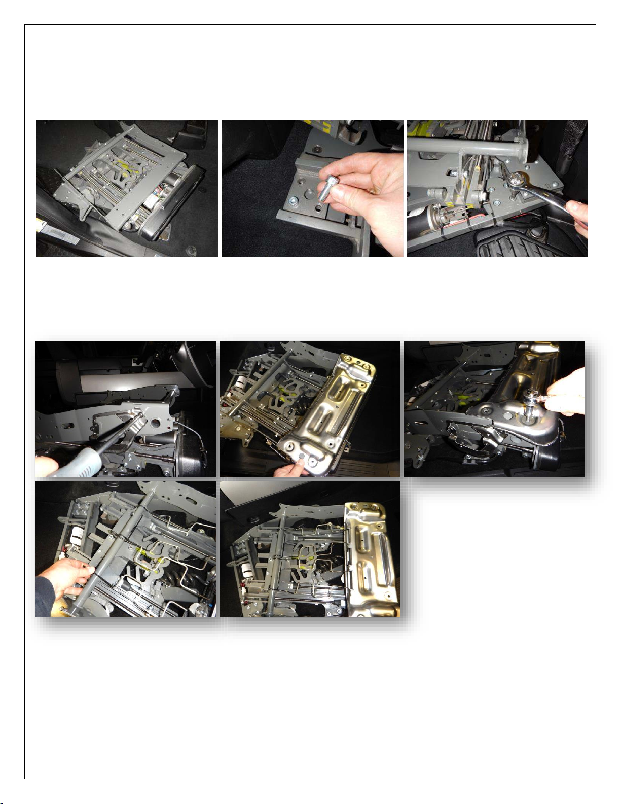
LINK 2007-2017 FORD EXPEDITION PASSENGER FRONT. p. 12
15. Place the LINK in the vehicle on the floor adapter. Use the four (4) 3/8’’-16 x 1¼’’ socket cap bolts to
secure the LINK by the pivot, and use the four (4) 3/8’’-16 x 7/8’’ to secure the interior of the LINK. Be
careful not to pinch the LINK wire harness between the LINK and the floor adapter.
IMPORTANT: Run the LINK harness around and under the pivot. Do not run over the
top of the pivot as it can interfere with the function of the slide.
16. Connect the previously installed 12V power supply to the LINK, and using the ‘BYPASS’ mode on
the tablet, carefully ‘PIVOT’ ‘TRAVEL’ and ‘TILT’ the LINK out of the vehicle. Install the plastic trim
support and seat pan using the OEM bolts. Then install the seat cushion supports.

LINK 2007-2017 FORD EXPEDITION PASSENGER FRONT. p. 13
17. The seat fan will have to modified and relocated to fit. There are plastic tabs that will have to be
removed to gain clearance.
REMOVE
REMOVE
REMOVE
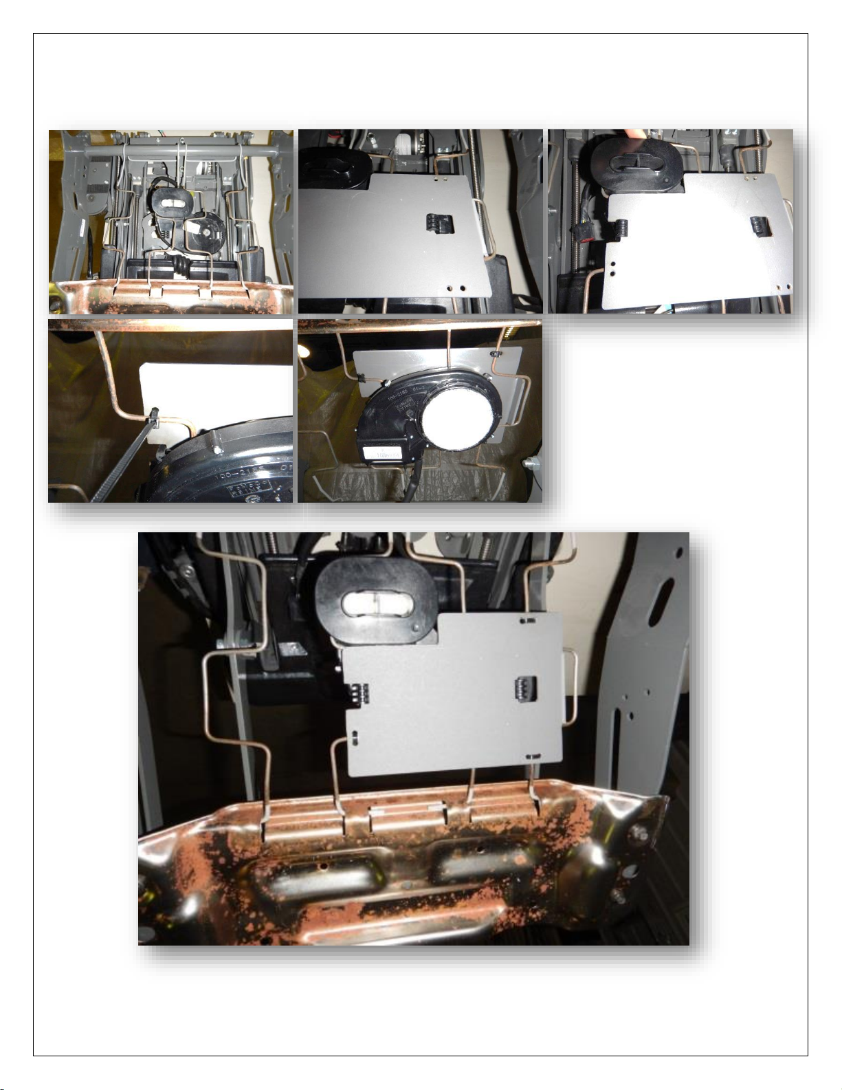
LINK 2007-2017 FORD EXPEDITION PASSENGER FRONT. p. 14
18. Reinstall the fan, place it under the seat cushion supports with the vent above the wire supports.
Use the provided plastic #LK -EXP07R-06 to hold it in position and then attach the plastic with the
provided zip ties.

LINK 2007-2017 FORD EXPEDITION PASSENGER FRONT. p. 15
19. The seat belt receiver can now be reinstalled to the seat base.
20. Using the ‘BYPASS’ mode on the tablet, tilt the seat up to be able to install the seat cushion onto
the LINK seat adapter. Attach the plastic clips with zip ties to ensure they do not un-clip.
This manual suits for next models
1
Table of contents


