Linkskey LKD-E415 User manual
Quick Installation Guide LKD-E415 CAT5 DVI KVM Extender o er LAN w/ Audio & Mic
1
Re . 1.1 Copyright @ All Rights Reser ed
Technical Support
E-mail: btitech@linkskey.com
Website: www.linkskey.com
Quick Installation Guide
LKD-E415
CAT5 DVI KVM Extender
over LAN w/ Audio&Mic
4 Ports USB 2.0 for Keyboard, Mouse
and High Speed Devices
Full HD 1080p Digital Video up to 100M
Thank you for purchasing the LKD-E415 CAT5 DVI KVM Extender!
With our highly reliable and quality product, users can enjoy
countless benefits from using this CAT5 DVI KVM Extender.
Introduction
The LKD-E415 CAT5 DVI KVM Extender o er LAN comprises two
distinct units, the Transmitter (TX) and the Recei er (RX) unit. It
allows fully access and control resources on TX unit from RX
unit o er a single standard Cat5 UTP Ethernet cable. The
LKD-E415 is a LAN based DVI KVM Extender that allows user to
access the computer from a remote console anywhere on your
existing local area network infrastructure.
The LKD-E415 CAT5 DVI KVM Extender offers the extension of
keyboard, mouse, digital ideo, audio, and USB 2.0 de ices
distances up to 328 feet (100m) away from your local computer
using a single standard Cat5 UTP Ethernet cable.
The LKD-E415 CAT5 DVI KVM Extender supports digital ideo
resolution up to 1920 x 1080@60Hz Full HD 1080p through a
maximum of 328 feet single standard Cat5 UTP Ethernet Cable,
while satisfying the optimal ideo quality. Furthermore, the
LKD-E415 CAT5 DVI KVM Extender supports Graphic Mode and
Video Mode selection to fit your display requirements. Graphic
Mode is optimized for graphic/text display iewing; while Video
Mode is best for dynamically changing ideo stream playing.
Package Contents
Please check whether you ha e the following items listed in the
packaging box.
1 x Transmitter (TX) Unit
1 x Recei er (RX) Unit
1 x Video, USB, Audio, and Microphone Integrated Cable
2 x Power Adapter (DC 9V)
1 x Quick Installation Guide
Note: IR Remote Control Unit Pack (Wired Transmitter and
Wired Recei er) is optional and sold separately.
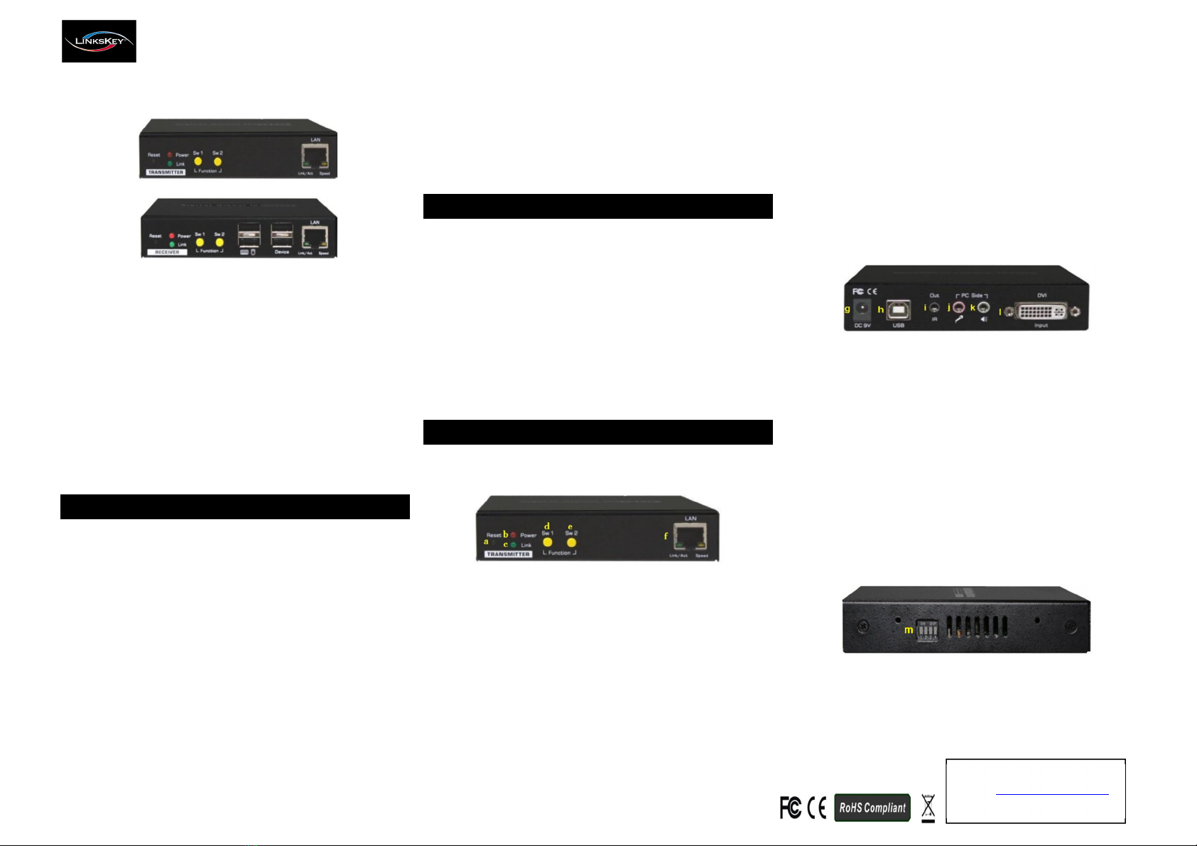
Panels Overview
Transmitter (TX) Unit:
Transmitter Front Panel O er iew
TX Front Panel:
a. Reset button (Press and hold for 1 second to completely
power cycle the unit)
b. Red Power LED (Solid: Power is on / OFF: Power is off /
Flas es: Unit initializing)
c. Green Link LED (Solid: Link established / OFF: No link or link
deacti ated on TX / Flas es: No digital ideo signal input,
link not established, or link deacti ated on RX)
d. Link Push Button Sw 1 (Toggle between link acti ate and link
deacti ate on TX)
e. Mode Push Button Sw 2 (Press and hold for 1 second then
release to toggle between the Video Mode and the Graphic
Mode on both TX and RX units at the same time; Press and
hold for 3 seconds then release to cycle between the
Anti-Dither 1(1bit), 2(2bit), or OFF(off) modes on both TX
and RX units at the same time)
f. RJ45 Ethernet Port (Connect to the RJ45 Ethernet Port on
the remote RX unit directly using a standard Cat5 UTP
Ethernet cable up to 328 feet(100 meters) or ia a Gigabit
Ethernet switch)
Transmitter Back Panel O er iew
TX Back Panel:
g. Power Jack (DC 9V)
h. USB Type B Port (Connect the USB cable from local
computer)
i. IR Remote Control Port Out (Connect the wired IR Remote
Control Transmitter to local computer, optional)
j. Microphone 3.5mm Jack (Connect the pink microphone
cable to local computer)
k. Audio 3.5mm Jack (Connect the green speaker cable to local
computer)
l. Monitor DVI-I Port Input (Connect the DVI-D ideo cable
from digital ideo signal output on local computer)
Transmitter Side Panel O er iew
TX Side Panel:
m. Group Address 4-Position Dip Switch (Set the four switches
position to match the Group Address of RX)
Quick Installation Guide LKD-E415 CAT5 DVI KVM Extender o er LAN w/ Audio & Mic
2
Re . 1.1 Copyright @ All Rights Reser ed
Technical Support
E-mail: btitech@linkskey.com
Website: www.linkskey.com
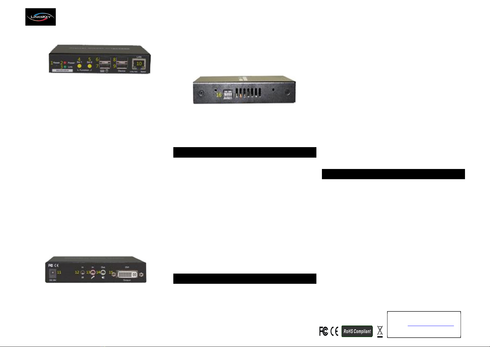
Receiver (RX) Unit:
Recei er Front Panel O er iew
RX Front Panel:
1. Reset button (Press and hold for 1 second to completely
power cycle the unit)
2. Red Power LED (Solid: Power is on / OFF: Power is off /
Flas es: Unit initializing)
3. Green Link LED (Solid: Link established / OFF: No link or
link deacti ated on RX / Flas es: No digital ideo signal
input on TX, link not established, or link deacti ated on TX)
4. Link Push Button Sw 1 (Toggle between link acti ate and
link deacti ate on RX)
5. Mode Push Button Sw 2 (Press and hold for 1 second then
release to toggle between the Video Mode and the
Graphic Mode on both TX and RX units at the same time;
Press and hold for 3 seconds then release to cycle between
the Anti-Dither 1(1bit), 2(2bit), or OFF(off) modes on both
TX and RX units at the same time)
6. USB Type A Port (For console keyboard)
7. USB Type A Port (For console mouse)
8. USB Type A De ice Port (For USB 2.0 high speed de ice)
9. USB Type A De ice Port (For USB 2.0 high speed de ice)
10. RJ45 Ethernet Port (Connect to the RJ45 Ethernet Port on
the remote TX unit directly using a standard Cat5 UTP
Ethernet cable up to 328 feet(100 meters) or ia a Gigabit
Ethernet switch)
Recei er Back Panel O er iew
RX Back Panel:
11. Power Jack (DC 9V)
12. IR Remote Control Port In (Connect the wired IR Remote
Control Recei er, optional)
13. Microphone 3.5mm Jack In (Connect the microphone)
14. Audio 3.5mm Jack Out (Connect the speaker)
15. Monitor DVI-I Port Output (Connect the DVI-D ideo cable
from local monitor)
Recei er Side Panel O er iew
RX Side Panel:
16. Group Address 4-Position Dip Switch (Set the four switches
position to match the Group Address of TX)
Pre-Installation
Before you install the two pieces of the CAT5 DVI KVM Extender,
you might consider the following:
•The Cat5 UTP Ethernet cable lengths between the
Transmitter and the Recei er you’ll use.
•In case of need to extend the Cat5 UTP Ethernet cable
lengths, install a Gigabit Ethernet Switch instead of Fast
Ethernet Switch to a oid the signal degradation.
•The location of your CAT5 DVI KVM Extender.
Note:
1. A good quality Cat5 UTP Ethernet cable pro ides better
quality of ideo transmission.
2. A oid installing cables near fluorescent lights, air-
conditioning equipment, power lines, or machines that
create electrical noise.
Installation
Take the package items out of the box and begin installation.
Note:
Before the installation, please check that the Group Address
4-Position Dip Switch of the Transmitter and Recei er units are
set to the same position/group (the DIP Switch from 1 to 4
switches default position setting is ON/TOP).
Installation:
1. Use the combo KVM cable pro ided with the unit, plug the
connectors on one end of the combo KVM cable into the
appropriate ports on the back panel of the Transmitter.
2. Plug the connectors on the other end of the combo KVM
cable into the appropriate ports on the local computer.
3. Connect the Transmitter and Recei er by using a Cat5 UTP
Ethernet cable ia RJ45 Ethernet Port on the front panel of
both units.
4. Connect the remote console keyboard, mouse, monitor,
speaker, and microphone into the appropriate ports on the
front and back panels of the Recei er unit.
Now, you ha e completed the installation and ready to operate.
Q&A
Q: For some reason the display of my system reduced its 1080p
resolution to lower, how do I fix it.
A: Please follow the firmware update process steps below to
re-initialize the connected monitors EDID information sa ed in
TX and RX units. Note that firmware update process is only
a ailable on Recei er (RX) unit.
1) Unplug the power from the RX unit.
2) Press and hold down the Sw 2 button then plug the power
back to the RX unit.
3) Release the Sw 2 button when the red Power LED flashes.
Other Linkskey Extender manuals


