SATEL ACX-201 3
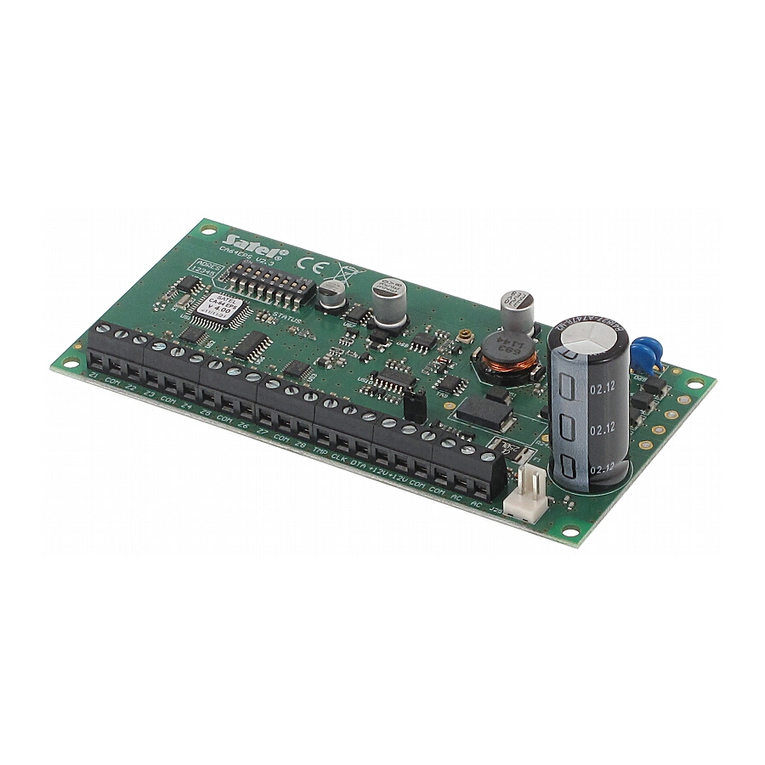
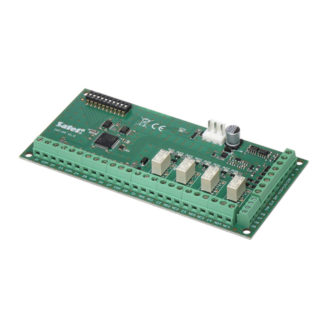
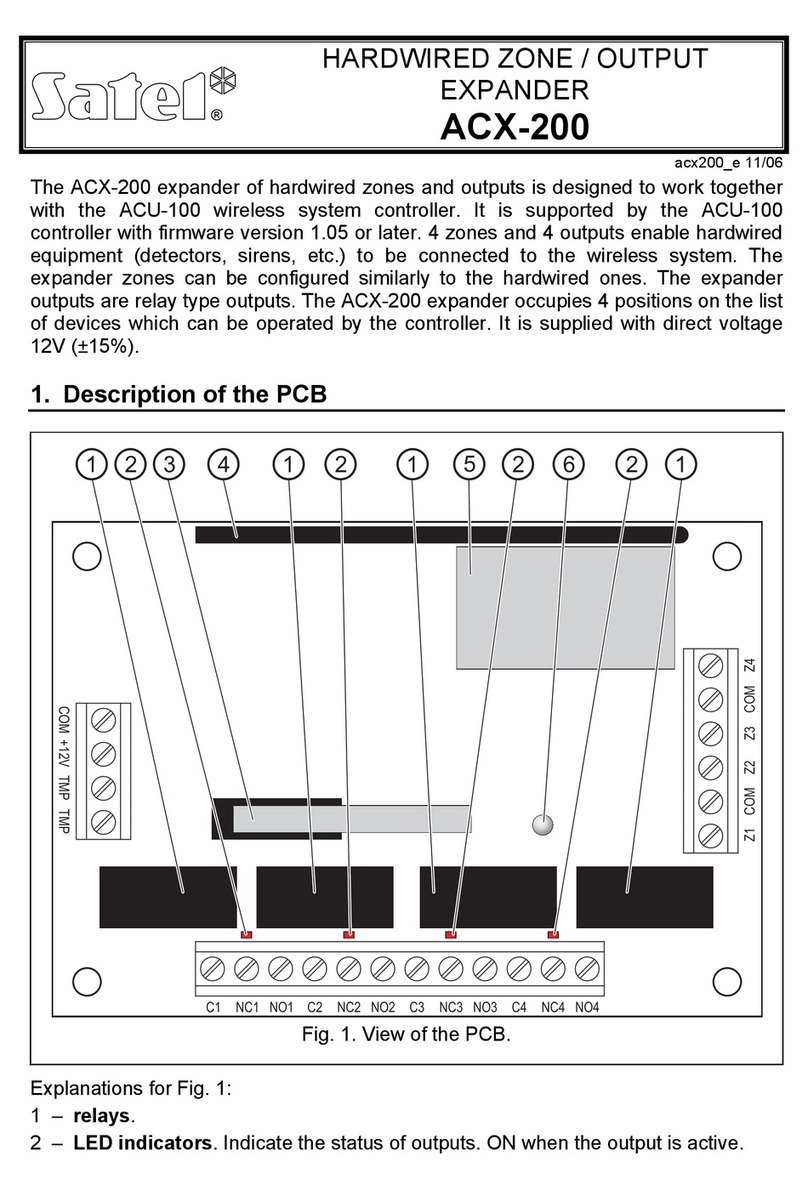
TMP - tamper input (NC) – if not used, it should be shorted to the common
ground.
Z1…Z4 - zone.
4. Installation
Disconnect power before making any electrical connections.
Never connect two devices with power supply unit to one transformer.
Before connecting transformer to a circuit from which it will be powered,
make sure the circuit is de-energized.
The device is designed for indoor installation. It is recommended that the expander be
mounted high above the floor. This will allow you to get a better range of radio
communication and avoid the risk of the expander being accidentally covered by
people moving around the premises.
The expander requires 18 V AC (±10%) supply voltage. The expander feeding
transformer must be permanently connected to the 230 V AC mains. At the place of
installation, an alternating current circuit that will be always alive must be available.
This circuit should be protected by a suitable safety device. Instruct the owner or user
of the alarm system on how the transformer should be disconnected from the mains
(e.g., indicate the fuse protecting the power circuit).
1. Use the ARF-100 tester to make sure that the radio signal level is adequate at the
location where the ACX-201 expander is to be installed. If the signal level is lower
than 40%, select another place for installation. Sometimes, it is sufficient to shift
the device ten or twenty centimeters to obtain a considerable improvement in the
signal quality.
2. Place the enclosure base against the wall and mark location of the mounting
holes.
3. Drill the holes in the wall for wall plugs (screw anchors).
4. Run the wires through the opening in the enclosure base (power wires, cables
connecting wired devices with the expander, etc.).
5. Using wall plugs (screw anchors) and screws, secure the enclosure base to the
wall.
6. Mount the expander board in the enclosure.
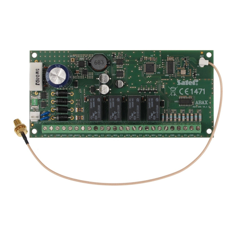
7. Secure the antenna and connect it to the socket on the electronics board.
8. Connect detectors to the expander zones. For the EOL configuration, use a 2.2 k
resistor, and for the 2EOL configuration – two 1.1 kresistors.
9. If the expander is to supervise the enclosure tamper switch, connect the wires of
tamper switch to the TMP and COM terminals. If the expander is not to supervise
the enclosure tamper switch, connect the TMP terminal to the expander COM
terminal.
10. Connect the devices to the expander outputs.
Note:Given the specific character of radio communication, it is not recommended that
the expander be used in applications where quick switchover of the output
status is expected.
