Huazheng Electric Manufacturing HZJF-9008 User manual

HZJF-9008 Handheld Partial
Discharge Detector
USER MANUAL
Huazheng Electric Manufacturing(Baoding) Co.,Ltd

Safety Terms and Symbols
This manual may contain the terms:
Warning!
Indicate the conditions and actions that may endanger the life and safety of the operator.
Attention!
Indicate the conditions and actions that may cause product damage or data loss.
The product may contain the terms:
Danger: when doing this, it may hurt you.
Warning: when doing this, it may cause potential dangers to you.
Attention: when doing this, it may cause damage to this product or other device connected to this
product.
The product may contain the symbols:
High Voltage! Please refer to the manual! Protective Earthing!
Attention! Keep the safety distance with the live device on field when working!!!

Product Certification and Standards
This product is suitable for the partial discharge test of high voltage equipment, for example,
the safely isolated transformer.
Normative References
The terms in following documents are the standard terms after they are referred by this
standard. For the references with dates, all subsequent modifications (exclusive of error published
contents) or revised editions are not applicable to this standard. For the references without dates, the
latest version is applicable to this standard.
GB/T 2423 Environmental test of electrical and electronic products
GB/T16927 High voltage test technology
GB/T 17626 Electromagnetic compatibility test and measurement technology
GB 2421 Basic environmental test rules for electrical and electronic products
GB7354 Partial discharge measurement
GB 11022 General technical conditions for high voltage switchgear
DL/T 417 Guide for partial discharge field measurement of electric power equipment
DL/T 593 Common technical requirements for high voltage switchgear and control
equipment standards
DL/T 595 Preventive test rules for electric power equipment

Safe conditions and actions, and conditions and actions may
damage the product
Notice for Operations Security
Understand the following safety precautions to avoid injury and prevent product damage or
other products connected to this device. As to avoid possible dangers, please use this product in
accordance with the regulations.
Use correct charger!
Use the special battery charger of this instrument. Otherwise, it may damage the battery of the
instrument.
Don’t open the cover for operations!
Don’t open the instrument case and operate this product.
Don’t operate when the product is suspected of failure!
If you suspect this product fails, please contact our maintenance staff for inspection. Any
maintenance and adjustment must be carried out by the maintenance staff of our company.
Please keep the product surface dry and clean.
As to avoid the equipment performance affected by the dust or moisture in the air, please keep
the product surface dry and clean.
Notice for Transport Safety
In order to avoid the screen, press key, knob or interface parts on equipment panel damage due
to the dropping during transport, please pay attention to the safety during transportation.
Be careful when inspecting on site!
Be careful when inspecting on site, as to avoid being knocked off by the
equipment on field. Make sure to keep the safe distance from the high-voltage
electrified equipment on field to avoid working under high risk field strength.

Contents
I. Product overview.................................................................................................................................................... 1
II. Product configuration............................................................................................................................................ 1
III. Technical parameters...........................................................................................................................................1
1. Conditions of usage...................................................................................................................................... 1
2. Technical performance................................................................................................................................. 2
IV. Appearance of equipment................................................................................................................................ 2
V. Introduction of software operation...................................................................................................................... 3
1. Introduction of key and boot........................................................................................................................ 3
2. Introduction of TEV partial discharge measurement interface.............................................................. 4
3. TEV pulse-count measurement interface..................................................................................................4
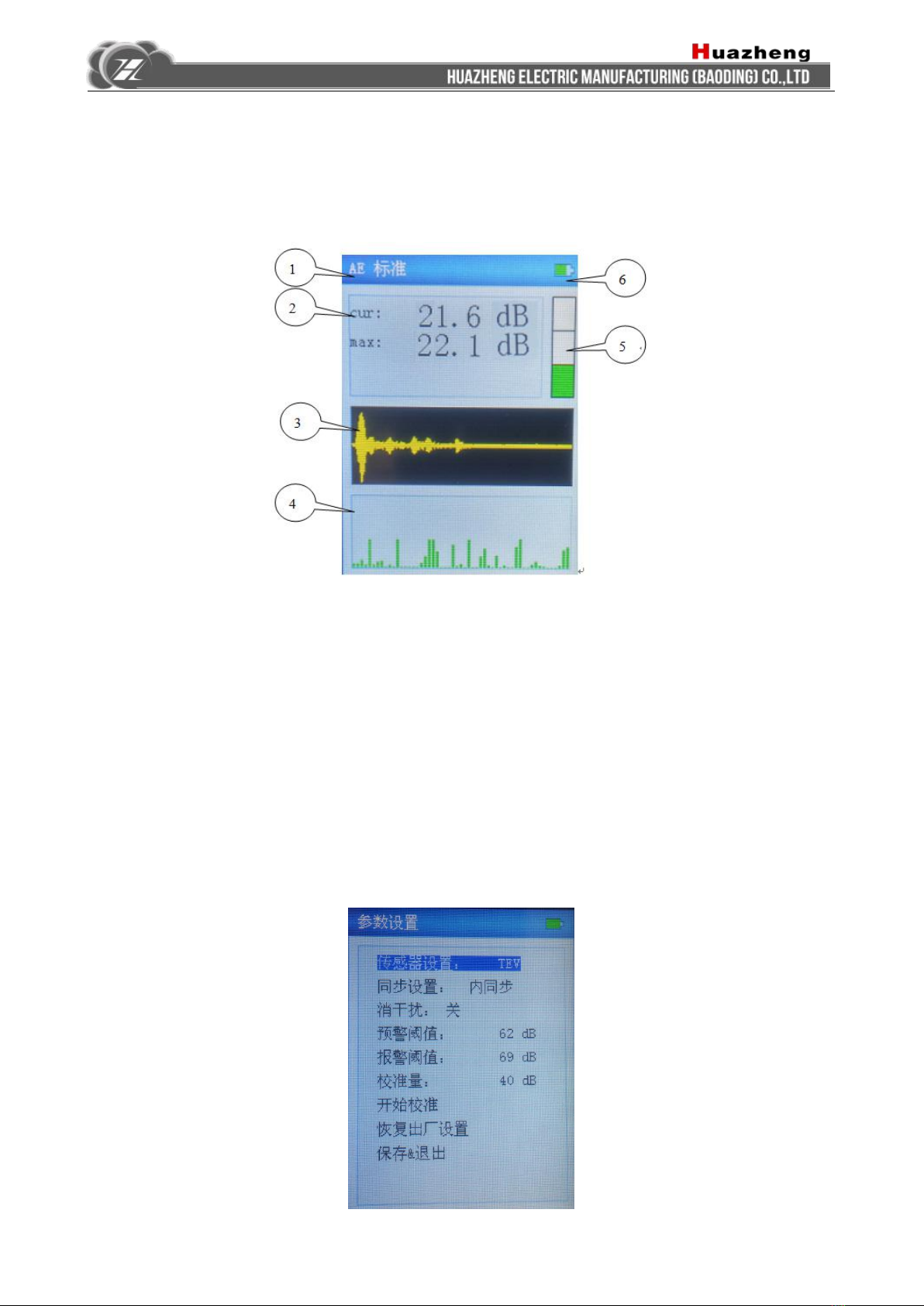
4. AE partial discharge measurement interface............................................................................................5
5. Parameter setting interface..........................................................................................................................5
6. Data storage, query playback and synchronization-frequency setting interface................................6
7. Detailed introduction of each functional interface....................................................................................8
VI. Introduction of partial discharge measurement............................................................................................ 10
1. TEV measurement:..................................................................................................................................... 10
2. AE measurement:........................................................................................................................................ 11
3. TEV external synchronization measurement:.........................................................................................11
VII. Partial discharge configuration table of HZJF-9008 switch cabinet.........................................................12

1
I. Product overview
This handheld partial-discharge instrument is mainly used for the
detection of high-voltage electrical equipment. This product is simple to
operate and adopts portable structure design which can inspect on line. It
equips with specific sensors to detect various high-pressure devices, which
can detect the insulation state changes inside the equipment timely. So the
insulation failure could be dealt with in time
II. Product configuration
Items
Description
Display screen
3.5 inch color LCD display screen; display resolution: 320 x 240
Sensor
Built-in AE\TEV
External interface
AE\TEV external interface, external synchronization interface, headphone
jack, Micro SD card (16G), charging port, USB port (Backup Interface,
extensible)
Signal interface mode
Front-end built-in AE\TEV sensor;
External sensor (Backup Interface, extensible with Lemo connector)
Shape & size
Length × Width × Height (225mm × 100mm × 40mm)
Weight
0.5kg
III. Technical parameters
1. Conditions of usage
The instrument is internally installed 18650 lithium battery, and the ambient temperature
under normal use condition: -20℃- 60℃, charging environment: 0℃- 45℃, storage environment:
-20℃- 45℃.
Attention: The instrument must be shut down when charging. If the device is on
charge, it cannot be started up for measurement.

2
2. Technical performance
1) sensor: built-in TEV sensor, ultrasonic sensor
2) range of frequency band: TEV: 3M-60MHz; ultrasonic: 40KHz
3) measurement range: TEV: 0dB-80dB; ultrasonic: 0dB-40dB
4) Tap: TEV: 0 -3 tap, total 4 adjustable taps; ultrasonic: 1 tap
5) maximum pulse / cycle number: 600
6) measurement display: current real-time value, historical maximum value, real-time oscillogram,
fingerprint diagram, trend diagram, pulse count
7) trigger mode: internal / external synchronization trigger
8) Power-on self-test function
9) data storage, query playback and derivation functions
10) interference suppression function
11) alarm threshold setting and indicating function: partial-discharge alarm indication (the color
indicator bar at right side), tap shift indication (suggest shifting tap in case of red), battery
power-quantity indication.
12) working power supply: high-capacity lithium battery pack, working for 6 hours with one time
charge.
13) peripheral storage interface: 16G MicroSD card
IV. Appearance of equipment
4.1 Appearance diagram of handheld partial-discharge patrolling measurement instrument
No.
Instruction
1
Built-in TEV sensor
2
Built-in ultrasonic sensor
3
External sensor signal interface (using
the special signal-line to connect the
sensor, for expanding backup)
4
External synchronization interface
5
Headphone jack
6
Charging interface
7
USB interface
8
SD card slot

3
V. Introduction of software operation
1. Introduction of key and boot
Fig.5.1.1 Key
1. OK key; 2, direction key; 3, menu key; 4, start / pause key; 5, power key
As shown in the figure above, long press the power key on the lower-left corner of the keypad
panel to enter the self-checking screen as the figure below; after successful self-checking, the
program is started up and entered the partial discharge measurement interface.
Fig. 5.1.2 Self-checking screen when starting
3
4
5
2
1

4
2. Introduction of TEV partial discharge measurement interface
Fig. 5.2 Main interface of TEV partial discharge measurement
The main interface of software startup is as shown in the figure above, total 7 parts; ①sensor
measurement mode and gain display, ②partial-discharge indicating value (current value, maximal
value in turn), ③finger-print diagram, ④tendency chart, ⑤oscillogram, ⑥partial-discharge
warning diagram, ⑦display of electricity quantity.
3. TEV pulse-count measurement interface
Fig. 5.3.1 TEV pulse count measurement interface
It can be switched to TEV pulse-count measurement interface by press the right key on TEV

5
partial discharge measurement interface; the software interface is shown as figure above; and there
are total 4 parts; ①sensor measurement mode and gain display, ②partial-discharge waveform
display area, ③display of maximal value, ④pulse number / s.
4. AE partial discharge measurement interface
Fig.5.4 AE partial discharge measurement interface
It can enter the parameter setting interface by press the menu key on TEV partial discharge
measurement interface; press the up and down keys to select the sensor settings and press the left
key to switch to AE sensor; after choosing the save & exit key, press the OK key to exit the menu
and enter the AE partial-discharge measurement interface, as shown in figure above; and there are
total 6 parts; ①sensor measurement mode display, ②partial-discharge indicating value (current
value, maximal value in turn), ③oscillogram, ④tendency chart, ⑤partial-discharge warning
diagram, ⑥display of electricity quantity.
5. Parameter setting interface

6
Fig.5.5.1 Parameter setting interface
Press the menu key to enter the parameter setting interface; press the up and down keys to
select the options need changing; there will be blue background displayed after selecting, and then
press the left and right keys to switch the parameters of this option, including:
1, sensor settings: TEV\AE switching.
2, synchronous setting: internal synchronization / external synchronous switching.
3, interference-elimination switch: the left and right keys are utilized to choose to open or close the
interference-elimination function. This function can filter the background noise to achieve the
purpose of interference suppression.
4, early-warning threshold: this default value is recommended, and no adjustment is needed in the
test process.
5, alarm threshold: this default value is recommended, and no adjustment is needed in the test
process.
6, calibration quantity: this default value is recommended, and no adjustment is needed in the test
process.
7, calibration-starting: if some test environments need calibrating, press the OK key to start the
calibration after changing calibration quantity; then press Save Key to save the data; after
calibration, press Save & Exit. The value has been calibrated before delivery; don’t conduct this
operation unless in special circumstances; press the Restore the Factory Setting to restore the
default value in case of careless operation.
8, factory-setting restoring: press to restore the factory default value.
9, Save & Exit: after setting all the parameters, press OK key to save and exit, and then continue to
measure.
6. Data storage, query playback and synchronization-frequency setting interface

7
Fig.5.6.1 Storage, phase, and synchronization settings interface
The menu option in the figure will appear when press the OK key on the TEV partial discharge
measurement interface and AE partial discharge interface; press the up and down keys to switch to
the data storage menu; after determining the number of equipment, press the OK key to store the
current data into SD card; it will prompt " date is being saved, the data is saved successfully".
Data playback: select the up and down keys to enter the data playback bar; press the OK key to
enter the data playback interface as the figure below:
Fig. 5.6.2 Data playback interface

8
Press the left and right keys to switch different equipments, and the up and down keys to
examine the data records saved in the equipment; and the real-time waveform, data, channel
and gain of the record under the selected equipment number can be displayed.
The prompt that "whether to delete the current record" will appear when press the OK key on
this interface; press the OK key to confirm the deletion, and press other keys to cancel the deletion.
After the playing back, press the menu key to return to the measurement interface.
Select the phase deviation, and then press the left and right keys to adjust the deviation value;
it will be found that the real-time waveform changes the phase position as the adjusted value; the
synchronization frequency is selected to adjust the deviation of the internal and external
synchronization. Internal and external synchronization setting shall be in reference to the parameter
interface. Then press the left and right keys to adjust the value, it will be found that the real-time
waveform gradually slows or stops, indicating that the synchronization frequency is consistent with
the synchronization source. The cooperative utilization of two functions of phase deviation
regulation and synchronous frequency can be regarded as the general basis for judging the discharge
signal (this function cannot be used for simple patrolling-measurement operations).
7. Detailed introduction of each functional interface
7.1 Status indicator bar
TEV standard mode and gain option will appear on the upper indicator bar of TEV partial
discharge measurement interface; press the up and down key to adjust the gain; there are 0-3 option
in total, and the battery indicator is displayed on the right side.
TEV pulse mode and gain option will appear on the upper indicator bar of TEV pulse counting
measurement interface (the option cannot be adjusted on this interface), and the battery indicator is
displayed on the right side.
AE sensor and battery indicator are displayed up the AE partial discharge measurement
interface.

9
The elimination-interference prompt will appear in the State Bar when the
elimination-interference function is opened.
The red rectangle-frame prompt will appear in Abnormal State when the external
synchronization is selected. After the external synchronization is normal, the red indicator will
disappear.
7.2 Partial-discharge indicating value
Fig. 7.2 partial-discharge indicating value
The current partial-discharge indicating value and the maximum partial-discharge indicating
value are shown in the figure above.
7.3 Fingerprint atlas
Fig. 7.3 Fingerprint atlas
The fingerprint reflects the value of 0~360° partial-discharge capacity. The upper limit of
discharge capacity changes with the gain adjustment, and the red & yellow tapered ribbon on the
right side indicates the range of partial-discharge capacity.

10
7.4 Historical trend chart
Fig. 7.4 Historical trend chart
The histogram is utilized to display the historical discharge records; each vertical column
represents the historical discharge capacity; green represents normal, yellow represents the early
warning and red represents warning.
7.5 Discharge capacity diagram
Fig. 7.5 Discharge capacity diagram
As shown in the figure, the diagram shows the current partial-discharge capacity level; green
represents normal, yellow represents the early warning and red represents warning.
VI. Introduction of partial discharge measurement
The measurement method of HZJF-9008 handheld partial discharge detector is simple; the
equipment needs no recalibration in actual measurement since the value has been calibrated before
delivery; it only needs to select the appropriate test mode (TEV\AE) and measure directly with the
built-in sensor.
1. TEV measurement:
The host shall be perpendicular to the surface of the equipment being tested so that the
front-end TEV sensor can place on the surface of high-voltage equipment, and then test different
locations to observe the changes of data and waveform, then the recorded data can be read.

11
2. AE measurement:
The AE sensor at the front of host shall be aimed at the gap of the measured equipment and
observe along the gap if the AE data and waveform changes, then read and record the data.
3. TEV external synchronization measurement:
External synchronization module can be added for testing when finding the suspicious
discharge signals and further measurements are needed. And then check the synchronization of
waveform and the Q- Φ-T diagram. The figure below shows the relation between the quantity of
electricity, phase and time.
Select the external synchronization in parameter settings, and red rectangle-frame prompt will
appear in the state indicator bar upside the equipment; then the external synchronization module
shall be connected with the 220VAC of the same power of the measured equipment. Then the signal
output end of the module is connected with the external synchronization interface of the main
engine using the special signal line; the red prompt rectangle in the state indicator bar upside the
equipment will disappear. The main engine shall be perpendicular to the surface of the equipment
being tested so that the front-end TEV sensor can place on the surface of high-voltage equipment,
and then test the suspicious discharge locations to observe the changes of data and waveform as
well as Q-Φ-T diagram with cooperation of synchronous frequency regulation, and then further
analysis and judgement are carried out to determine whether it is a discharge signal.

12
VII. Partial discharge configuration table of HZJF-9008 switch
cabinet
No.
Name & Content
Quantity
1
HZJF-9008 handheld partial discharge Detector
1 set
2
HZJF-9008 handheld partial-discharge patrolling measurement
instrument embedded software
1 set
3
HZJF-9008 External synchronization module and twin-core power line
1 set
4
Charger and twin-core power line
1 set
5
Outer synchronous connecting line
1 pc
6
TEV sensor
1 set
7
Partial-discharge ultrasonic sensor
1 set
8
Wiring
1 set
9
Protective housing
1
10
"Product Factory Materials"
1 set
11
"User Manual"
1
Table of contents
Other Huazheng Electric Manufacturing Security Sensor manuals
Popular Security Sensor manuals by other brands

PCB Piezotronics
PCB Piezotronics IMI SENSORS 682A05 Installation and operating manual

SECO-LARM
SECO-LARM E-931CS22RRCQ installation manual

Honeywell
Honeywell Ex-Or MR2500D Installation and commissioning instructions

Bosch
Bosch ISC-PPR1-W16G installation instructions

Rokonet
Rokonet ShockTec installation instructions

Banner
Banner SLLVE23-350 instruction manual