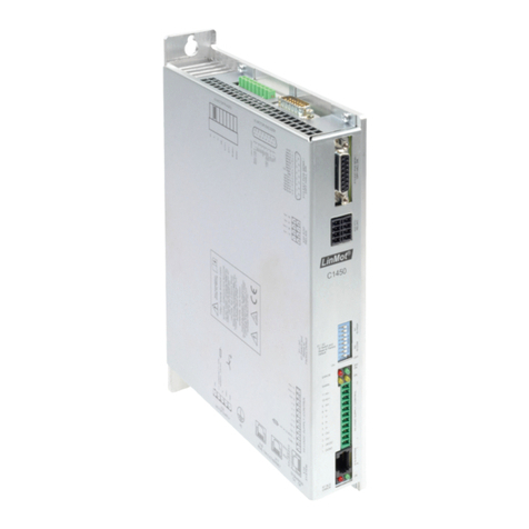
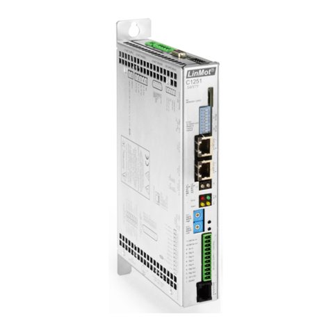
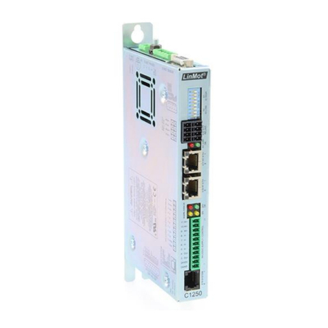
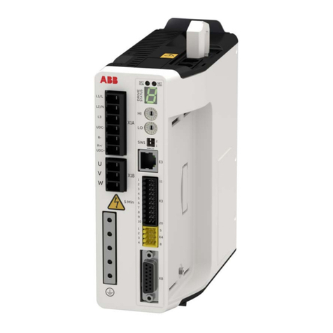
LinMot C1250-IP Series Installation and operating instructions

March 2020
0185-1120-E_1V5_AN_PLC_Commissioning
PLC Commissioning of LinMot Servo Drives
Application Note / How-to

© 2020 NTI AG
This work is protected by copyright.
Under the copyright laws, this publication may not be reproduced or transmitted in any form, electronic or
mechanical, including photocopying, recording, microfilm, storing in an information retrieval system, not even for
didactical use, or translating, in whole or in part, without the prior written consent of NTI AG.
LinMot® is a registered trademark of NTI AG.
Note
The information in this documentation reflects the stage of development at the time of press and is therefore
without obligation. NTI AG reserves itself the right to make changes at any time and without notice to reflect
further technical advance or product improvement.
NTI AG
LinMot®
Bodenaeckerstrasse 2
CH-8957 Spreitenbach
Tel: +41 56 419 91 91
Fax: +41 56 419 91 92
Email: office@linmot.com
Homepage: www.linmot.com

PLC Commissioning
NTI AG / LinMot
Page 3 of 205
Table of Contents
Table of Contents ..................................................................................................................................................3
Use of This Document ..........................................................................................................................................8
Version History ......................................................................................................................................................8
Trademarks ............................................................................................................................................................9
1 General ..............................................................................................................................................................10
1.1 Abbreviations.................................................................................................................................................10
1.1.1 LinMot Drive System Generations (SG)...................................................................................................10
1.1.2 LinMot Drive Interface Extensions ...........................................................................................................10
1.2 Available LinMot Libraries .............................................................................................................................10
1.3 Documentation / User Manuals.....................................................................................................................11
1.4 UPID (Unique Parameter ID) ........................................................................................................................12
1.5 Recent Version of LinMot-Talk and Drive Firmware......................................................................................12
2 Overview ...........................................................................................................................................................13
2.1 LinMot Profile (Commissioning using the LinMot Libraries)..........................................................................13
2.2 Drive Profiles (Direct Integration as Motion Axis using standardized Drive Profiles)....................................14
3 LinMot Profile: Beckhoff TwinCAT 2&3..........................................................................................................15
3.1 Overview .......................................................................................................................................................15
3.2 Configuration and Connection of the LinMot Drive .......................................................................................16
3.2.1 Motor Configuration..................................................................................................................................16
3.2.2 XML Files .................................................................................................................................................16
3.2.3 EtherCAT Connection ..............................................................................................................................16
3.3 PLC Setup EtherCAT (E1450-EC-QN, E1250-EC-UC, C1x00-EC-XC-xx)...................................................17
3.3.1 Insert LinMot Drive as Slave ....................................................................................................................17
3.3.2 Config Module ..........................................................................................................................................18
3.3.3 Links to PLC Control ................................................................................................................................19
3.3.4 Check EoE settings..................................................................................................................................20
3.4 Check with LinMot-Talk if the Fieldbus is running .........................................................................................21
4 LinMot Profile: Siemens TIA ...........................................................................................................................22
4.1 Overview .......................................................................................................................................................22
4.2 Configuration and Connection of the LinMot Drive .......................................................................................23
4.2.1 Motor configuration ..................................................................................................................................23
4.2.2 GSD / GSDML files ..................................................................................................................................23
4.2.3 PROFIBUS Connection ...........................................................................................................................23
4.2.4 PROFINET Connection............................................................................................................................25
4.3 PLC Setup PROFIBUS (E1430-DP-QN, E1230-DP-UC, E1130-DP-xx) ......................................................26
4.4 PLC Setup PROFINET (E1450-PN-QN, E1250-PN-UC, C1250-PN-UC, C1150PN-UC) ............................28
4.4.1 Assigning the Device Name and IP Address............................................................................................30
4.5 Check with LinMot-Talk if the Fieldbus is running .........................................................................................33
5 LinMot Profile: Rockwell RSLogix 5000 / Logix Designer............................................................................34
5.1 Overview .......................................................................................................................................................34
5.2 Minimum Requirements ................................................................................................................................34
5.3 Configuration and Connection of the LinMot Drive .......................................................................................35
5.3.1 Motor Configuration..................................................................................................................................35
5.3.2 EDS Files (Requires RSLogix 5000 V20 or higher) .................................................................................35
5.3.3 EtherNet/IP Connection ...........................................................................................................................35
5.3.4 IP Address ................................................................................................................................................35
5.4 PLC Setup EtherNet/IP .................................................................................................................................36
5.4.1 RSLinx Classic .........................................................................................................................................36
5.4.2 Add a LinMot drive using AOP (E1250-IP-xx, C1250-IP-xx)....................................................................37

PLC Commissioning
Page 4 of 205
NTI AG / LinMot
5.4.3 Add a LinMot drive using the EDS file (recommended for Studio <V31) .................................................41
5.4.4 Add a LinMot drive as Generic Ethernet Module (ETHERNET-MODULE)..............................................44
5.5 Check with LinMot-Talk if the Fieldbus is running .........................................................................................46
6 Drive Profile: Siemens TIA, PROFIdrive.........................................................................................................47
6.1 Overview .......................................................................................................................................................47
6.2 Configuration and Connection of the LinMot Drive .......................................................................................48
6.2.1 Motor Configuration..................................................................................................................................48
6.2.2 GSDML File..............................................................................................................................................49
6.2.3 PROFINET Connection............................................................................................................................49
6.3 PLC Setup .....................................................................................................................................................50
6.3.1 Install GSDML File(s) ...............................................................................................................................50
6.3.2 Insert the LinMot Drive as Device ............................................................................................................50
6.3.3 Set PROFINET Name and IP Address ....................................................................................................51
6.3.4 Insert and Setup a new Technology object (Linear Axis) .........................................................................53
6.3.5 Insert and Setup a new Technology object (Rotary Axis) ........................................................................59
6.4 Home / Set Reference...................................................................................................................................65
6.4.1 Home the Linear Axis ...............................................................................................................................65
6.4.2 Home / Set Reference of the Rotary Axis ................................................................................................67
6.4.3 Active Homing for both linear and rotary motors......................................................................................68
6.5 Parameter Access (RAM)..............................................................................................................................70
6.6 Add Additional Parameters / Variables to the Real-Time Channel ...............................................................71
6.6.1 Drive Configuration ..................................................................................................................................71
6.6.2 PLC Configuration....................................................................................................................................72
6.7 Tuning the Control Loops ..............................................................................................................................73
6.7.1 Drive Control Loop ...................................................................................................................................73
6.7.2 PLC Control Loop.....................................................................................................................................75
6.8 Check with LinMot-Talk if the Fieldbus is running .........................................................................................76
7 Drive Profile: Rockwell Motion using PVA Streaming (CIP Sync) ...............................................................77
7.1 Overview .......................................................................................................................................................77
8 Drive Profile: Beckhoff TwinCAT 2/3, SoE .....................................................................................................78
8.1 Overview .......................................................................................................................................................78
8.2 Configuration and Connection of the LinMot Drive .......................................................................................79
8.2.1 Motor Configuration..................................................................................................................................79
8.2.2 XML File ...................................................................................................................................................80
8.2.3 EtherCAT Connection ..............................................................................................................................80
8.3 PLC Setup .....................................................................................................................................................81
8.3.1 EtherCAT Device Description File XML ...................................................................................................81
8.3.2 Scanning the EtherCAT for new Devices .................................................................................................81
8.3.3 Setting up the Process Data of the LinMot Drive .....................................................................................83
8.3.4 Check EoE settings..................................................................................................................................85
8.3.5 Setting up the NC Axis .............................................................................................................................86
8.4 Encoder Parameter Examples for Linear and Rotary Motors .......................................................................88
8.4.1 Linear Motors PS01 / PS10 .....................................................................................................................88
8.4.2 Rotary Motors RS01 & RS02 ...................................................................................................................88
8.4.3 Rotary Motors EC02.................................................................................................................................89
8.4.4 Other motors ............................................................................................................................................89
8.5 Homing ..........................................................................................................................................................90
8.6 Visualization ..................................................................................................................................................91
8.7 Drive Reset....................................................................................................................................................91
8.8 Asynchronous Parameter Access .................................................................................................................92
8.9 Add Additional Parameters or Variables to the Process Data (MDT 1 / AT 1) ..............................................94

PLC Commissioning
NTI AG / LinMot
Page 5 of 205
9 Drive Profile: Beckhoff TwinCAT 2/3, CoE DS402.........................................................................................97
9.1 Overview .......................................................................................................................................................97
9.2 Configuration and Connection of the LinMot Drive .......................................................................................98
9.2.1 Motor Configuration..................................................................................................................................98
9.2.2 XML File ...................................................................................................................................................99
9.2.3 EtherCAT Connection ..............................................................................................................................99
9.3 PLC Setup ...................................................................................................................................................100
9.3.1 EtherCAT Device Description File XML .................................................................................................100
9.3.2 Scanning the EtherCAT for new Devices ...............................................................................................100
9.3.3 Setting up the Process Data of the LinMot Drive ...................................................................................102
9.3.4 Check EoE settings................................................................................................................................104
9.3.5 Setting up the NC Axis ...........................................................................................................................105
9.4 Encoder Parameter Examples for Linear and Rotary Motors (Axis > Enc) ................................................107
9.4.1 Linear Motors PS01 / PS10 ...................................................................................................................107
9.4.2 Rotary Motors RS01 & RS02 .................................................................................................................107
9.4.3 Rotary Motors EC02...............................................................................................................................108
9.4.4 Other motors ..........................................................................................................................................108
9.5 Homing ........................................................................................................................................................109
9.6 Visualization ................................................................................................................................................110
9.7 Drive Reset.................................................................................................................................................. 110
9.8 Asynchronous Parameter Access ................................................................................................................111
9.9 Add Positive and Negative torque/force limit (0x1711) to the Process Data .............................................. 113
9.10 Add Additional Parameters or Variables to the Process Data................................................................... 115
10 Drive Profile: Schneider Electric PacDrive 3, FSP_DRIVE.......................................................................119
10.1 Overview ...................................................................................................................................................119
10.2 Configuration and Connection of the LinMot Drive ...................................................................................120
10.2.1 Motor Configuration..............................................................................................................................120
10.2.2 Sercos Connection...............................................................................................................................121
10.2.3 Sercos Address ....................................................................................................................................122
10.3 PLC Setup .................................................................................................................................................123
10.3.1 General Device Properties ...................................................................................................................123
10.3.2 Add the LinMot Drive to the Sercos .....................................................................................................124
10.3.3 Device Configuration............................................................................................................................125
10.3.3.1 Identification ....................................................................................................................................125
10.3.3.2 Motor/Mechanic using a LinMot linear motor..................................................................................126
10.3.3.3 Motor/Mechanic using a rotary motor .............................................................................................127
10.3.3.4 Realtime channel ............................................................................................................................128
10.4 Homing (Linear Motors) ............................................................................................................................129
10.4.1 Homing using the Schneider template (FB_Home) .............................................................................129
10.4.1.1 Setup...............................................................................................................................................129
10.4.2 Drive-Based Homing (S-0-0148)..........................................................................................................130
10.5 Parameter Access .....................................................................................................................................131
10.5.1 Supported UPID Functions via IDN Access over the Sercos Service Channel ...................................131
10.5.2 Read RAM Parameter Example...........................................................................................................132
10.5.3 Write RAM Parameter Example ...........................................................................................................133
10.6 Enable/Disable Drive Warnings ................................................................................................................134
11 Drive Profile: CODESYS SoftMotion, CiA402 ............................................................................................135
11.1 Overview....................................................................................................................................................135
11.2 Configuration and Connection of the LinMot Drive ...................................................................................136
11.2.1 Motor Configuration..............................................................................................................................136
11.2.2 XML File ...............................................................................................................................................137

PLC Commissioning
Page 6 of 205
NTI AG / LinMot
11.2.3 EtherCAT Connection...........................................................................................................................137
11.3 PLC Setup .................................................................................................................................................138
11.3.1 EtherCAT Device Description File XML................................................................................................138
11.3.2 Add and setup the LinMot drive............................................................................................................138
11.3.3 Check EoE settings ..............................................................................................................................140
11.4 Homing ......................................................................................................................................................141
11.5 Visualization ..............................................................................................................................................142
11.6 Parameter Access .....................................................................................................................................143
11.7 Add Additional Parameters or Variables to the Process Data ...................................................................144
12 Drive Profile: B&R NC Motion using the SDC interface ...........................................................................147
12.1 Overview ...................................................................................................................................................147
12.2 Compatibility LinMot_SDC <> ACP10 ARNC0 .........................................................................................148
12.3 Configuration and Connection of the LinMot Drive ...................................................................................149
12.3.1 Motor Configuration..............................................................................................................................149
12.3.2 XDD File ...............................................................................................................................................150
12.3.3 Powerlink Connection ..........................................................................................................................150
12.3.4 Node ID ................................................................................................................................................150
12.4 Short Description of the LinMot SDC interface function block ..................................................................151
12.4.1 Principle of Operation...........................................................................................................................151
12.4.2 HTML Help ...........................................................................................................................................151
12.4.3 LM_SdcIf (Interface Function Block)....................................................................................................152
12.4.4 enCallType ...........................................................................................................................................152
12.4.5 stConfig ................................................................................................................................................152
12.5 Prerequisites .............................................................................................................................................153
12.6 Automation Studio Physical View..............................................................................................................154
12.6.1 Add the LinMot drive to the Powerlink network ....................................................................................154
12.6.2 Configuration........................................................................................................................................155
12.6.3 I/O Mapping..........................................................................................................................................156
12.6.4 Powerlink Interface and PLC Configuration .........................................................................................157
12.6.5 Add a B&R drive to generate all NC object specific requirements automatically ................................158
12.7 Automation Studio Configuration View......................................................................................................160
12.7.1 Setup NC Manager and NC Mapping ..................................................................................................160
12.7.2 Add new NC Object..............................................................................................................................162
12.7.3 Add TextSystem ...................................................................................................................................163
12.8 Automation Studio Logical View: Linear Motor Example ..........................................................................165
12.8.1 Add the example program to the project ..............................................................................................165
12.8.2 ACOPOS Parameter Table...................................................................................................................165
12.8.3 Init Parameter Table .............................................................................................................................166
12.8.4 Check Init Parameters of the SDC function block................................................................................167
12.8.5 Assign the example program to Cyclic #1............................................................................................167
12.9 Automation Studio Logical View: Rotary Motor Example..........................................................................168
12.9.1 Add the example program to the project ..............................................................................................168
12.9.2 ACOPOS Parameter Table...................................................................................................................169
12.9.3 Init Parameter Table .............................................................................................................................171
12.9.4 Check Init Parameters of the SDC function block................................................................................172
12.9.5 Assign the example program to Cyclic #1............................................................................................172
12.10 Homing ....................................................................................................................................................173
12.10.1 Linear Motor .......................................................................................................................................173
12.10.2 Rotary Motor ......................................................................................................................................173
12.10.3 Reference Switch (mcHOME_ABS_SWITCH) ..................................................................................174
12.11 Test ..........................................................................................................................................................176

PLC Commissioning
NTI AG / LinMot
Page 7 of 205
12.11.1 Switch On ...........................................................................................................................................176
12.11.2 Homing ...............................................................................................................................................177
12.11.3 Error Acknowledge .............................................................................................................................177
12.12 Parameter Access ...................................................................................................................................178
12.12.1 Parameter access by LMcf_ParaAccess function block ....................................................................178
12.12.2 Parameter access by SDO commands..............................................................................................179
12.13 Add Additional Parameters or Variables to the Process Data.................................................................181
12.14 Errors (LM_SdcIf outputs) .......................................................................................................................182
12.14.1 bError .................................................................................................................................................182
12.14.2 diStatusID...........................................................................................................................................182
12.14.3 uiErrorCode ........................................................................................................................................182
13 Drive Profile: OMRON Sysmac Studio, CoE DS402..................................................................................183
13.1 Overview ...................................................................................................................................................183
13.2 Configuration and Connection of the LinMot Drive ...................................................................................184
13.2.1 Motor Configuration..............................................................................................................................184
13.2.2 XML File ...............................................................................................................................................185
13.2.3 EtherCAT Connection ..........................................................................................................................185
13.3 PLC Setup .................................................................................................................................................186
13.3.1 EtherCAT Device Description File XML ...............................................................................................186
13.3.2 Define EtherCAT node address on LinMot-Device ..............................................................................186
13.3.2.1 Set node address by address selector on device ...........................................................................187
13.3.2.2 Set node address by parameter on device .....................................................................................188
13.3.2.3 Set node address by EtherCAT Master ..........................................................................................189
13.3.3 Scanning the EtherCAT for new Devices .............................................................................................190
13.3.4 Create a motion axis and link it to your physical LinMot axis ..............................................................191
13.3.5 Setting up the motion axis....................................................................................................................193
13.4 Drive based homing ..................................................................................................................................194
13.4.1 Settings on LinMot drive ......................................................................................................................194
13.4.2 Function blocks required on Sysmac ...................................................................................................195
13.4.2.1 EC_CoESDOWrite ..........................................................................................................................195
13.4.2.2 MC_ResetFollowingError................................................................................................................195
13.4.2.3 MC_HomeWithParameter...............................................................................................................195
13.4.3 Homing procedure on Sysmac.............................................................................................................196
13.5 Drive Reset................................................................................................................................................197
13.6 Parameter Access .....................................................................................................................................198
13.7 Add Additional Parameters or Variables to the Process Data (PDO Map) ...............................................199
14 Troubleshooting ...........................................................................................................................................200
Appendix I: Basic Position Control Loop Tuning ..........................................................................................202
Notes ..................................................................................................................................................................204
Contact & Support.............................................................................................................................................205

PLC Commissioning
Page 8 of 205
NTI AG / LinMot
Use of This Document
This document is an Application Note / How-To to help the user connecting LinMot drives to different PLC types.
It provides guides when using function block libraries provided by NTI AG / LinMot and guides to integrate
LinMot drives using standardized drive profiles.
This document is provided by NTI AG / LinMot free of charge with no warranty for updates.
Also, LinMot accepts no liability for damages that may be caused by using this document or programming
examples referred to.
Drives: Various
Classification: [x] Application Note
[x] Installation Guide
[x] User Manual
[x] Documentation
[x] LinMot internally
Version History
Version
Date
Author
Description
1V0
31/05/2017
fj
Initial Release
1V1
13/06/2017
fj
Minor corrections
1V2
10/07/2017
fj
Added chapter 11 Drive Profile: CODESYS SoftMotion, CiA402
1V3
27/03/2019
fj / mm
Added chapter 7 Drive Profile: Rockwell Motion using PVA Streaming (CIP Sync)
Added chapter 8.4 Encoder Parameter Examples for Linear and Rotary Motors
Added chapter 9 Drive Profile: Beckhoff TwinCAT 2/3, CoE DS402
Added chapter 10.3.3.3 Motor/Mechanic using a rotary motor
Added chapter 12 Drive Profile: B&R NC Motion using the SDC interface
Updated chapter 6 Drive Profile: Siemens TIA, PROFIdrive
Removed chapter OMRON with EC drives (obsolete)
Various minor updates and corrections
1V4
03/06/2019
fj
Minor: added library compatibility list: chapter 12.2
Minor: fixed screenshot and description in chapter 12.13
1V5
26/02/2020
fj
Added chapter 10.4.1 Homing using the Schneider template (FB_Home)
Added chapter Trademarks
Various minor updates and corrections

PLC Commissioning
NTI AG / LinMot
Page 9 of 205
Trademarks
Product and company names and logos referenced may be either trademarks or registered trademarks of their
respective companies. The sole purpose of any trademarks in this document is the identification of the
corresponding products.
Company
Trademarks / Registered Trademarks
Siemens AG
SIEMENS®, SIMATIC®, TIA Portal®, Step 7®
Rockwell Automation, Inc
Rockwell Automation®, Allen-Bradley®, CompactLogix™, ControlLogix®, Studio 5000®, Studio
5000 Logix Designer®, RSLogix 5000®, Stratix®, RSLinx®,
Beckhoff Automation GmbH
Beckhoff®, TwinCAT®, EtherCAT®, Safety over EtherCAT®
Schneider Electric
PacDrive®, SoMachine®
Bosch Rexroth
IndraControl, IndraMotion
3S-Smart Software Solutions GmbH
CODESYS
B&R Industrial Automation GmbH
B&R Automation Studio®, Ethernet POWERLINK®
Omron
SYSMAC®,
Profibus and Profinet International (P.I.)
Profibus®, Profinet®
Interests Group SERCOS interface e.V
SERCOS interface®
ODVA, Inc
EtherNet/IP™, CIP™, CIP Sync™,
All other product and company names and marks mentioned in this document are the property of their
respective owners and are mentioned for identification purposes only.

PLC Commissioning
Page 10 of 205
NTI AG / LinMot
1 General
1.1 Abbreviations
1.1.1 LinMot Drive System Generations (SG)
SG
Drives
SG3
Family E1100 (GP, CO, DN, DP) (LC/HC/XC)
SG4
Family B1100 (VF, PP, GP, ML) (LC/HC/XC)
SG5
Family E1200 (GP, DP, DS, EC, IP, PD, PL, PN, SC, SE, LU)
Family E1400 (GP, DP, DS, EC, IP, PD, PL, PN, SC, SE, LU) (0S/1S)
Family B8000-ML (GP, EC, IP, PL, PN, SC)
SG6
Family C1250 (DS, EC, CM, IP, PD, PL, PN, SC, SE, LU) (0S/1S)
Family E1400V2 (GP, DP, DS, EC, IP, PD, PL, PN, SC, SE, LU) (0S/1S)
Family C1400 (GP, DS, EC, IP, PD, PL, PN, SC, SE, LU) (0S/1S)
SG7
Family A1100
Family C1100 (GP, DS, EC, PD, PN, SE) (0S/1S)
1.1.2 LinMot Drive Interface Extensions
Extension
Interface
GP
General Purpose (Depends on system generation and installed FW: LinRS and/or CANopen and/or DeviceNet)
CO
CANopen (LinMot Profile)
DN
DeviceNet (LinMot Profile)
DP
PROFIBUS (LinMot Profile)
PN
PROFINET (LinMot Profile)
PD
PROFIdrive (PROFIdrive Standard Telegram 5 & 9, SIEMENS Telegram 105)
EC
EtherCAT (LinMot Profile)
SE
EtherCAT SoE (Servo Drive Profile over EtherCAT)
DS
EtherCAT CoE (DS402, CiA402)
PL
Powerlink (LinMot Profile)
IP
EtherNet/IP (LinMot Profile)
CM
EtherNet/IP (CIP Sync, LinMot Profile)
SC
Sercos III (FSP_DRIVE, FSP_IO)
LU
LinUDP (LinMot Ethernet UDP protocol)
RS
LinRS (LinMot serial protocol for RS232, RS422, RS485)
E.g. C1250-SE-XC-xS -> SE = EtherCAT SoE
1.2 Available LinMot Libraries
LinMot provides several function block libraries for different PLCs and fieldbus systems to allow a fast and
comfortable integration of LinMot drives into almost any control concept.
An overview of available LinMot libraries can be downloaded from the LinMot website:
http://www.linmot.com/support/plc-library/
Or search for the document reference (0185-1105) in the LinMot eCatalogue:
http://shop.linmot.com
Note: The available libraries can be downloaded from: http://download.linmot.com/plc_lib/libraries
For preliminary libraries that are not available for download please contact the LinMot support team.

PLC Commissioning
NTI AG / LinMot
Page 11 of 205
1.3 Documentation / User Manuals
Beside the documentation included in the libraries available for download, reading the following user manuals is
essential to understand the communication between the PLC and the LinMot drive. The manuals are included in
the LinMot-Talk software (Menu Manuals → All Documents or Relevant Documents if logged in to a drive) or can
be downloaded from the LinMot eCatalogue (search by document reference): http://shop.linmot.com
User Manuals: General
System Generation
Document Reference
LinMot-Talk
All
0185-1059
Motion Control Software
SG3 & SG4
0185-1092
Motion Control Software
SG5 - SG7
0185-1093
User Manuals: Configuration Over Fieldbus
System Generation
Document Reference
Drive Configuration Over Fieldbus
SG3
0185-1072
Drive Configuration Over Fieldbus
SG4
0185-1073
Drive Configuration Over Fieldbus
SG5 - SG7
0185-1074
User Manuals: Interfaces
System Generation
Document Reference
EtherCAT (LinMot Profile)
SG5 - SG7
0185-1079
EtherCAT SoE (Servo Drive Profile over EtherCAT)
SG5 - SG7
0185-1080
EtherCAT CoE (CiA402, CANopen over EtherCAT)
SG5 - SG7
0185-1103
PROFIBUS DP
SG3, SG5 & SG6
0185-1089
PROFINET IO
SG5 - SG7
0185-1090
PROFINET PROFIdrive
SG6
0185-1132
Sercos III (FSP_DRIVE or FSP_IO)
SG5 & SG6
0185-1091
EtherNet/IP
SG5 & SG6
0185-1081
EtherNet/IP CIP Sync
SG6
0185-1165
Powerlink
SG5 & SG6
0185-1088
CANopen
SG3 & SG4
0185-1075
CANopen
SG5 - SG7
0185-1076
DeviceNet
SG3 & SG4
0185-1078
LinRS (LinMot serial protocol)
SG3 - SG7
0185-1082
LinUDP (Linmot Ethernet UDP protocol) up to FW6.3
SG5 & SG6
0185-1083
LinUDP V2 (LinMot Ethernet UDP protocol) from FW6.3
SG5 & SG6
0185-1108

PLC Commissioning
Page 12 of 205
NTI AG / LinMot
1.4 UPID (Unique Parameter ID)
The value of any parameter of a LinMot drive is stored as an integer value (raw data) in the memory space of
the drive. The parameter is identified through its Unique Parameter ID (UPID), which is a 16 Bit integer number.
Note: Detailed information about LinMot drive parameters can be found in the user manual Drive
Configuration Over Fieldbus. See chapter 1.3 Documentation / User Manuals
Attention ROM Access:
Intense use of writing into the ROM memory can reduce the lifetime of the drive memory!
More details can be found in the Drive Configuration Over Fieldbus (0185-1074) user manual
> see chapter Documentation / User Manuals
1.5 Recent Version of LinMot-Talk and Drive Firmware
The most recent LinMot-Talk version including all drive firmware, device description files and documentation can
be downloaded from
either:
https://linmot.com/download/linmot-talk-drive-configuration/
or:
http://download.linmot.com/LinMot-Talk/Release/
Hint:
LinMot C1250, C1450 & E1450 series drives support configuration over several interfaces (ProfiNet,
EtherNet/IP, EtherCAT, Sercos III & LinUDP). This allows to login with LinMot-Talk into the drive and
change parameters, monitor the drive, import/export the drive configuration, etc.
Please request the according application note from support@linmot.com

PLC Commissioning
NTI AG / LinMot
Page 13 of 205
2 Overview
2.1 LinMot Profile (Commissioning using the LinMot Libraries)
The following table shows working combinations of different PLC types and LinMot drives. For these
combinations function block libraries and/or example projects are available. Click the link in the See chapter
column to directly open the according chapter (if available).
PLC Type
Interface
LinMot I/F Extension
Type
Language
See chapter
Beckhoff TwinCAT 2&3
EtherCAT
CANopen
PROFIBUS
-EC
-GP
-DP
Library
ST (Structured Text)
3
Siemens Step 7 V5.5
(S7-300 and higher)
PROFINET
PROFIBUS
-PN
-DP
Library
AWL
4
Siemens TIA
(S7-300, S7-1500)
PROFINET
PROFIBUS
-PN
-DP
Library
AWL
4
Siemens TIA
(S7-1200, S7-1500)
PROFINET
PROFIBUS
-PN
-DP
Library
SCL
4
Rockwell Automation
EtherNet/IP
-IP
Addon Instructions (AOI)
LD (Ladder)
5
B&R
Powerlink
CANopen
-PL
-GP
Library
ST
Not yet
CODESYS 2.x / 3.x
Various
Various
Library
ST
Not yet

PLC Commissioning
Page 14 of 205
NTI AG / LinMot
2.2 Drive Profiles (Direct Integration as Motion Axis using standardized Drive Profiles)
The following table shows the drive profiles supported by LinMot servo drives. Based on your PLC type the
correct LinMot drive can be selected. Click the link in the See chapter column to directly open the according
chapter (if available).
PLC Type
Interface
LinMot I/F Extension
Integration
Drive Profile
See chapter
Siemens
(Simotion, S7-1500, …)
PROFIdrive
-PD
As axis
Standard Telegram 5
SIEMENS Telegram 105
6
Rockwell Automation
EtherNet/IP (CIP Sync)
-CM
As motion axis
LinMot PVA Streaming
7
Beckhoff TwinCAT 2&3
EtherCAT SoE
-SE
As NC axis
SoE
8
Beckhoff TwinCAT 2&3
EtherCAT CoE
-DS
As NC axis
CoE (DS402)
9
Schneider Electric
(PacDrive 3)
Sercos III
-SC
As axis
FSP_DRIVE
10
Bosch Rexroth
(IndraControl /
IndraMotion)
Sercos III
-SC
As axis
FSP_DRIVE
Footnote 1
CODESYS Motion
EtherCAT CoE
-DS
As axis
CoE (DS402)
11
TRIO MC464
(P680)
EtherCAT
-EC
As axis
TRIO specific
Footnote 2
B&R
Powerlink
-PL
As SDC axis
LinMot PV Streaming
12
Omron
(NJ501-1500)
EtherCAT CoE
-DS
As axis
CoE (DS402)
13
1
See Bosch Rexroth online help for GAT compact. The LinMot Sercos (-SC) drives are integrated
as sercosDrive.
2
Contact TRIO Motion for help to integrate. They have directly integrated LinMot EtherCAT drives (-
EC) in their firmware.

PLC Commissioning
NTI AG / LinMot
Page 15 of 205
3 LinMot Profile: Beckhoff TwinCAT 2&3
3.1 Overview
This chapter shows how a LinMot C1250-EC-XC-0S drive (with LinMot EtherCAT interface) can be integrated
and setup in a Beckhoff TwinCAT environment to be used with the library provided by LinMot. For this example,
TwinCAT 2 is used. The steps are generally similar for TwinCAT 3.
The library for TwinCAT 2&3 can be downloaded from:
http://download.linmot.com/plc_lib/libraries/Beckhoff/ (named Beckhoff_LinMot_Library_...)
Note:
More information can be found in the library documentation (part of the above-mentioned download)
and in the user manual EtherCAT (LinMot Profile) (see chapter 1.3 Documentation / User Manuals)
Image Source: http://www.beckhoff.com/
EtherCAT is the open real-time Ethernet network originally developed by Beckhoff. The LinMot acts as Slave in
this network and is implemented with the standard ASIC ET1100 from Beckhoff.
For further information on the EtherCAT fieldbus please visit:
http://www.ethercat.org/
additional device (s)

PLC Commissioning
Page 16 of 205
NTI AG / LinMot
3.2 Configuration and Connection of the LinMot Drive
The LinMot drive is configured using the LinMot-Talk software:
http://www.linmot.com/download/linmot-talk-drive-configuration/
3.2.1 Motor Configuration
It is assumed that the motor connected to the drive is already configured.
Use the Motor Wizard inside LinMot-Talk to setup the motor (Menu -> Drive -> Motor Wizard):
See Appendix I: Basic Position Control Loop Tuning
3.2.2 XML Files
Install the XML file that is part of the LinMot-Talk software/firmware you are using.
The most recent device files are always part of the newest LinMot-Talk software. They are located by default:
•EtherCAT: \\LinMot-Talk X.X Build XXXXXXXX\Firmware\Interfaces\EtherCAT\XML
3.2.3 EtherCAT Connection
The drive is connected to the EtherCAT network using the X17 & X18 connectors.
The below pictures show the ports of an E1250-EC-UC drive. On all other LinMot drives supporting EtherCAT
the ports are named the same (X17 & X18) but they may be placed differently on the drive housing.

PLC Commissioning
NTI AG / LinMot
Page 17 of 205
3.3 PLC Setup EtherCAT (E1450-EC-QN, E1250-EC-UC, C1x00-EC-XC-xx)
3.3.1 Insert LinMot Drive as Slave
The required XML files can be found in the following folder (default):
C:\Program Files\LinMot\LinMot-Talk X.X Build XXXXXXXX\Firmware\Interfaces\EtherCAT\XML
These files have to be copied to the IO folder of TwinCAT:
•C:\TwinCAT\Io\EtherCAT\ (for TwinCAT 2)
•C:\TwinCAT\3.1\Config\Io\EtherCAT\ (for TwinCAT 3)
Note: You may have to restart the developing environment to have the new XML file to be recognized.
Insert a new device by right-click on the EtherCAT-Master and Append Box (figure below) or restart
the PLC to “Config Mode” and scan for the devices attached to the EtherCAT bus.

PLC Commissioning
Page 18 of 205
NTI AG / LinMot
3.3.2 Config Module
The Config Module provides access to parameters, curve profiles, command table and so on of a LinMot drive.
If the config function blocks of the library are used the „Config Module“ inputs and outputs (0x1B08 &
0x1708) have to be enabled and linked as well.

PLC Commissioning
NTI AG / LinMot
Page 19 of 205
3.3.3 Links to PLC Control
To be able to link the input and output data of the LinMot drive you have to create an instance of the tstLM_Axis
data type (part of the library) in the global variables of you PLC project.
The inputs and outputs of the modules must be linked as shown below:
Hint:
It is possible to change multiple links at once. Just select the names you want to link > right-click >
Change Multi Link. Don’t forget to check “All Types” and “Continuous”.

PLC Commissioning
Page 20 of 205
NTI AG / LinMot
3.3.4 Check EoE settings
On supported drives (C1250-..., C1450-… & E1450-...) please check the EoE (Ethernet over EtherCAT)
settings.
LinMot drives do NOT support the DHCP mode yet. A fix IP must be assigned (select IP Address) or the EoE
feature must be completely disabled (disable Virtual Ethernet Port).
Note:
EoE can be used to login into the drive with LinMot-Talk directly over EtherCAT.
E.g. to change drive settings or for monitoring and tracing.
This manual suits for next models
18
Table of contents
Other LinMot Servo Drive manuals
LinMot
LinMot E1250-IP-UC User manual
LinMot
LinMot E1450-PL-QN-0S User manual
LinMot
LinMot C1100 series User manual
LinMot
LinMot C1200 User manual
LinMot
LinMot C1250 Series User manual

LinMot
LinMot C1450 VS-1S Series User manual
LinMot
LinMot C1251-2S User manual
LinMot
LinMot E14 0 V2 Series User manual
LinMot
LinMot C1400-CI-VS-0S-YYY User manual
LinMot
LinMot E1200 Series User manual
