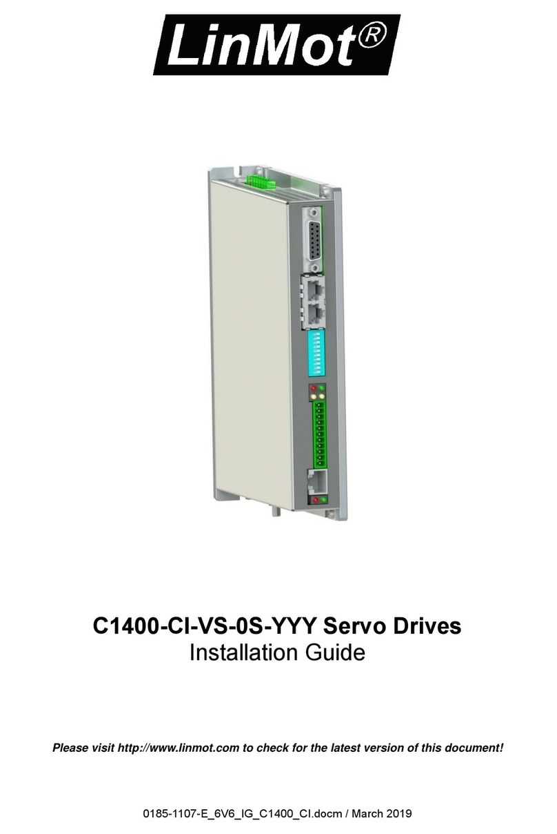
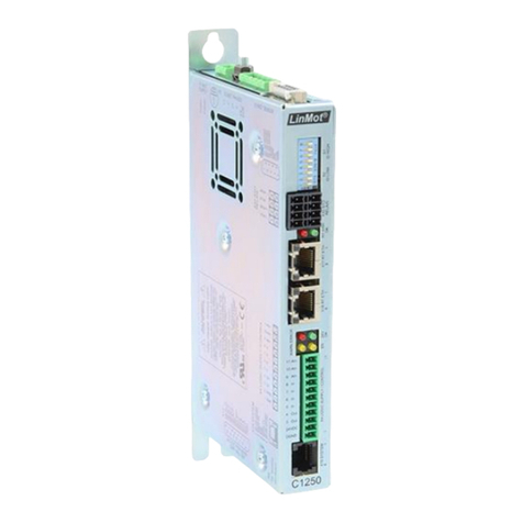
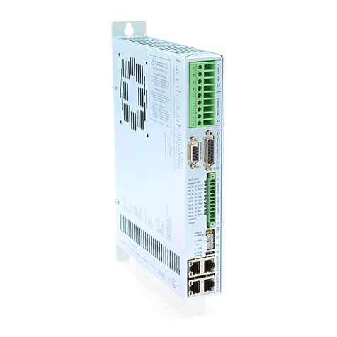
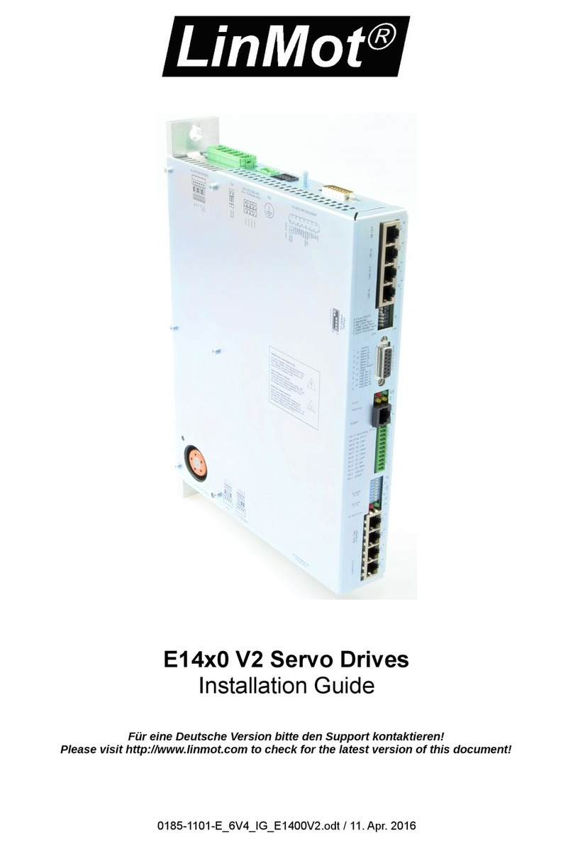
Installation Guide Servo Drives ENG
Page 2 / 29 C1250-MI NTI AG / LinMot
Content
1General Information ...................................................................................................................................... 3
1.1 Introduction......................................................................................................................................... 3
1.2 Explanation of Symbols ......................................................................................................................... 3
1.3 Qualified Personnel............................................................................................................................... 3
1.4 Liability................................................................................................................................................ 3
1.5 Copyright............................................................................................................................................. 3
2Safety Instructions......................................................................................................................................... 4
3System Overview........................................................................................................................................... 6
4Interfaces ..................................................................................................................................................... 7
5Functionality................................................................................................................................................. 8
6Software....................................................................................................................................................... 8
7Power Supply and Grounding ......................................................................................................................... 9
8Calibrated Measuring Amplifier (C1250-MI-XC-xS-Cxx).................................................................................... 10
9Description of the connectors / Interfaces ..................................................................................................... 10
9.1 PE ..................................................................................................................................................... 10
9.2 X1 ..................................................................................................................................................... 10
9.3 X2/X3 Motor-Connection..................................................................................................................... 11
9.4 X4 ..................................................................................................................................................... 12
9.5 X13.................................................................................................................................................... 12
9.6 X17 –X18........................................................................................................................................... 13
9.7 X19.................................................................................................................................................... 13
9.8 X33.................................................................................................................................................... 13
9.9 S1 –S2............................................................................................................................................... 14
9.10 System LEDs....................................................................................................................................... 14
9.11 RT Bus LED’s....................................................................................................................................... 14
10 System LED Blink Codes........................................................................................................................... 15
11 Safety Wiring.......................................................................................................................................... 16
12 Physical Dimension ................................................................................................................................. 18
13 Power Supply Requirements.................................................................................................................... 19
13.1 Motor Power Supply ........................................................................................................................... 19
13.2 Signal Power Supply............................................................................................................................ 19
14 Regeneration ......................................................................................................................................... 19
15 Safety notes for the installation according to UL........................................................................................ 20
16 Ordering Information.............................................................................................................................. 21
17 International Certifications ...................................................................................................................... 22
17.1 IECEE CB SCHEME –CB test certificate ....................................................................................... 23
17.2 UL Listing......................................................................................................................................... 26
17.3 EU Declaration of Conformity CE Marking ...................................................................................... 27
17.4 UK Declaration of Conformity UKCA Marking ................................................................................. 28


