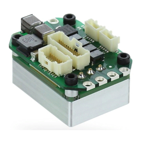
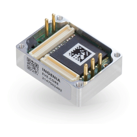
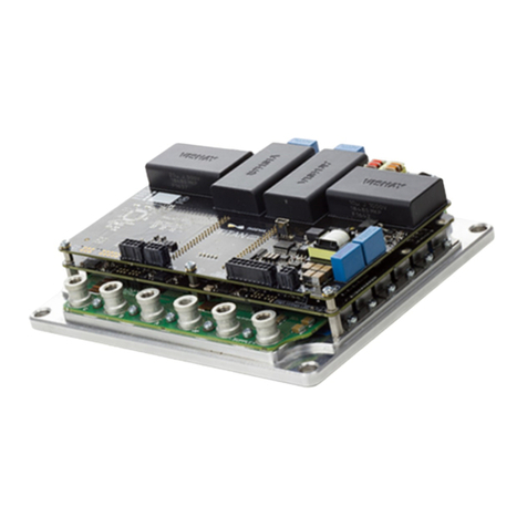
INGENIA Nix series User manual

INGENIA-CAT S.L.
8-14 MARIE CURIE, ADVANCED INDUSTRY PARK
08042 BARCELONA
Nix Product Manual
Edition 01/22/2019
For the most up to date information visit the online manual.

1 Table of Contents
1 Table of Contents 2
2 General Information 5
2.1 Manual revision history ...................................................................................................................................... 5
2.2 Disclaimers and limitations of liability .............................................................................................................. 5
2.3 Contact ................................................................................................................................................................ 5
3 Safety Information 7
3.1 About this manual............................................................................................................................................... 7
3.2 Warnings.............................................................................................................................................................. 7
3.3 Precautions ......................................................................................................................................................... 7
4 Product Description 8
4.1 Nix part numbering............................................................................................................................................. 8
4.2 Specifications.................................................................................................................................................... 10
4.3 Hardware revisions ........................................................................................................................................... 13
4.4 Power and current ratings................................................................................................................................ 14
4.4.1 Power losses calculation (heat dissipation).................................................................................................... 15
4.4.2 Current ratings .................................................................................................................................................. 16
4.4.3 Dynamic application (non-constant current).................................................................................................. 18
4.4.4 System temperature......................................................................................................................................... 19
4.4.5 Improving heat dissipation with a heatsink .................................................................................................... 20
4.5 Architecture....................................................................................................................................................... 20
5 Connectors Guide 22
5.1 Connectors position and pinout of Nix with onboard connectors (NIX-x/xx-y-C) ......................................... 22
5.1.1 Supply and shunt connector ............................................................................................................................ 23
5.1.2 Motor connector ............................................................................................................................................... 24
5.1.3 Micro-Match connectors mating ...................................................................................................................... 26
Ribbon cable ..................................................................................................................................................... 26
Multi-core crimpedcable.................................................................................................................................. 27
5.1.4 Feedback connector ......................................................................................................................................... 29
5.1.5 Absolute encoder connector ............................................................................................................................ 31
5.1.6 I/O connector.................................................................................................................................................... 33
5.1.7 USB connector.................................................................................................................................................. 35
5.1.8 CAN connector.................................................................................................................................................. 37
Cleverly wiring CAN buses from standard DB9 connectors ............................................................................ 38
5.1.9 RS485 interface connector .............................................................................................................................. 39
5.2 Connectors position and pinout of Nix with gold plated pin headers (NIX-x/xx-y-P).................................... 41
5.2.1 Integrating the Nix with pin headers on a PCB................................................................................................ 45
Dimensions........................................................................................................................................................ 45
Mating connectors ............................................................................................................................................ 47
5.3 Nix with Quick Connectors Board (NIX-x/xx-y-Q) ............................................................................................ 48
5.4 Connectors position and pinout of Nix with EtherCAT (NIX-x/xx-E-z)............................................................ 50
5.4.1 EtherCAT connectors ....................................................................................................................................... 51
6 Signalling LEDs 52
6.1 Power and operation signalling LEDs.............................................................................................................. 52
6.2 CAN signalling LEDs .......................................................................................................................................... 53
6.3 EtherCAT signalling LEDs.................................................................................................................................. 54
7 Wiring and Connections 56
7.1 Protective earth ................................................................................................................................................ 56
7.2 Power supply..................................................................................................................................................... 58
7.2.1 Power supply requirements ............................................................................................................................. 59
Inrush current.................................................................................................................................................... 59
7.2.2 Power supply connection................................................................................................................................. 60

7.2.3 Battery connection ........................................................................................................................................... 61
7.2.4 Connection of multiple drives with the same power supply .......................................................................... 62
7.2.5 Power supply wiring recommendations.......................................................................................................... 63
Wire section....................................................................................................................................................... 63
Wire ferrules ...................................................................................................................................................... 63
Wire length ........................................................................................................................................................ 63
7.3 Motor and shunt braking resistor..................................................................................................................... 63
7.3.1 AC and DC brushless motors ............................................................................................................................ 63
7.3.2 DC motors and voice coils actuators ............................................................................................................... 65
7.3.3 Motor wiring recommendations ...................................................................................................................... 66
Wire section ...................................................................................................................................................... 66
Wire ferrules ...................................................................................................................................................... 66
Motor choke ...................................................................................................................................................... 67
Wire length ........................................................................................................................................................ 67
7.3.4 Shunt braking resistor ...................................................................................................................................... 67
7.4 Feedback connections...................................................................................................................................... 69
7.4.1 Digital Halls interface........................................................................................................................................ 69
7.4.2 Analog Halls interface....................................................................................................................................... 71
7.4.3 Digital Incremental Encoder............................................................................................................................. 73
Digital encoders with single ended 24 V outputs ............................................................................................ 75
Digital encoders with differential 24 V outputs............................................................................................... 76
Encoder broken wire detection........................................................................................................................ 76
7.4.4 Analog encoder (Sin-Cos encoder) interface................................................................................................... 76
7.4.5 Absolute encoder interface .............................................................................................................................. 79
7.4.6 Digital input feedback - PWM encoder............................................................................................................. 80
7.4.7 Analog input feedback...................................................................................................................................... 82
Potentiometer................................................................................................................................................... 82
DC tachometer .................................................................................................................................................. 83
7.4.8 Feedback wiring recommendations ................................................................................................................ 84
Recommendations for applications witch close feedback and motor lines ................................................. 84
7.5 I/O connections................................................................................................................................................. 84
7.5.1 General purpose single ended digital inputs interface (GPI1, GPI2).............................................................. 85
7.5.2 High-speed digital inputs interface(HS_GPI1, HS_GPI2) ............................................................................... 87
7.5.3 Analog inputs interface (AN_IN1, AN_IN2)....................................................................................................... 92
7.5.4 Digital outputs interface (GPO1, GPO2)........................................................................................................... 94
Wiring of 5V loads.............................................................................................................................................. 96
Wiring of 24V loads............................................................................................................................................ 96
7.5.5 Motor brake output (GPO1, GPO2)................................................................................................................... 98
7.5.6 Torque off input (custom purchase order) ...................................................................................................... 99
7.6 Command sources .......................................................................................................................................... 100
7.6.1 Network communication interface................................................................................................................ 101
7.6.2 Standalone ...................................................................................................................................................... 101
7.6.3 Analog input .................................................................................................................................................... 101
7.6.4 Step and direction........................................................................................................................................... 102
7.6.5 PWM command ............................................................................................................................................... 103
Single input mode........................................................................................................................................... 103
Dual input mode ............................................................................................................................................. 104
7.6.6 Encoder following or electronic gearing........................................................................................................ 105
7.7 Communications............................................................................................................................................. 106
7.7.1 USB interface................................................................................................................................................... 107
USB powered drive ......................................................................................................................................... 107
USB wiring recommendations ....................................................................................................................... 107
7.7.2 RS485 interface ............................................................................................................................................... 108
Multi-point connection using daisy chain ..................................................................................................... 109
7.7.3 CANopen interface.......................................................................................................................................... 111
CAN interface for PC........................................................................................................................................ 113
CAN wiring recommendations ....................................................................................................................... 113
7.7.4 EtherCAT interface.......................................................................................................................................... 114
8 Dimensions and Assembly 116
8.1 NIX-x/xx-y-C (Nix with onboard connectors) ................................................................................................. 116
8.2 NIX-x/xx-y-P (Nix with gold plated pin headers)............................................................................................ 117
8.3 NIX-x/xx-y-Q (Nix with Quick connectors board)........................................................................................... 118
8.4 NIX-x/xx-E-C (Nix with EtherCAT) ................................................................................................................... 119
8.5 Assembly Instructions..................................................................................................................................... 120
8.5.1 Heatsinks......................................................................................................................................................... 120
8.5.2 Thermal interface material............................................................................................................................. 121
9 Software 123
9.1 Configuration .................................................................................................................................................. 123
9.2 Applications..................................................................................................................................................... 123
9.3 Arduino ............................................................................................................................................................ 123
10 Service 124

Nix Product Manual|General Information
INGENIA |01/22/2019 5
2General Information
2.1 Manual revision history
v1 December 2015 Preliminary draft. --
v2 February 2016 Manual public release. Download
v3 April 2016 Added EtherCAT information. Structure improvements. Download
v4 November 2016 Minor improvements. Download
v5 February 2017 Aesthetics and structure improvements. Wiring information
improved.
Download
v6 May 2017 Improved PDF export format. Download
v7 January 2019 Fixed broken images links Download
Revision Release Date Changes PDF
For the most up to date information use the online Nix Product Manual. The PDF manual is generated only after
major changes.
Please refer toproduct hardware revisionspage for information on previous hardware revisions and changes.
2.2 Disclaimers and limitations of liability
The information contained within this document contains proprietary information belonging toINGENIA-CAT S.L..
Such information is supplied solely for the purpose of assisting users of the product in its installation.
INGENIA-CAT S.L.rejects all liability for errors or omissions in the information or the product or in other
documents mentioned in this document.
The text and graphics included in this document are for the purpose of illustration and reference only. The
specifications on which they are based are subject to change without notice.
This document may contain technical or other types of inaccuracies.The information contained within this
document is subject to change without notice and should not be construed as a commitment byINGENIA-CAT
S.L..INGENIA-CAT S.L.assumes no responsibility for any errors that may appear in this document.
Some countries do not allow the limitation or exclusion of liability for accidental or consequential damages,
meaning that the limits or exclusions stated above may not be valid in some cases.
2.3 Contact
INGENIA-CAT, S.L.
C/ Avila 124, 2-B
08018 Barcelona
SPAIN

Nix Product Manual|General Information
INGENIA |01/22/2019 6
Telephone: +34 932 917 682
E-mail: [email protected]
Web site: www.ingeniamc.com

Nix Product Manual|Safety Information
INGENIA |01/22/2019 7
3 Safety Information
3.1 About this manual
Read carefully this chapter to raise your awareness of potential risks and hazards when working with the Nix Servo
Drive.
To ensure maximum safety in operating the Nix Servo Drive, it is essential to follow the procedures included in this
guide. This information is provided to protect users and their working area when using the Nix Servo Drive, as well
as other hardware that may be connected to it. Please read this chapter carefully before starting the installation
process.Please also make sure all system components are properly grounded.
3.2 Warnings
The following statements should be considered to avoid serious injury to those individuals performing the
procedures and/or damage to the equipment:
•To prevent the formation of electric arcs, as well as dangers to personnel and electrical contacts, never
connect/disconnect the Nix Servo Drive while the power supply is on.
•Disconnect the Nix Servo Drive from all power sources before proceeding with any possible wiring change.
•After turning off the power and disconnecting the equipment power source, wait at least 10 seconds before
touching any parts of the controller that are electrically charged or hot.
3.3 Precautions
The following statements should be considered to avoid serious injury to those individuals performing the
procedures and/or damage to the equipment:
•The Nix Servo Drive components temperature may exceed 100 ºC during operation.
•Some components become electrically charged during and after operation. Expect voltages > 100 V that
could be lethal.
•The power supply connected to this controller should comply with the parameters specified in this
document.
• When connecting the Nix Servo Drive to an approvedpower source, do so through a line that is separate
from any possible dangerous voltages, using the necessary insulation in accordance with safety standards.
•High-performance motion control equipment can move rapidly with very high forces. Unexpected motion
may occur especially during product commissioning. Keep clear of any operational machinery and never
touch them while they are working.
•Do not make any connections to any internal circuitry. Only connections to designated connectors are
allowed.
•All service and maintenance must be performed by qualified personnel.
•Before turning on the Nix Servo Drive, check that all safety precautions have been followed, as well as the
installation procedures.

Nix Product Manual|Product Description
INGENIA |01/22/2019 8
4 Product Description
The Nix DigitalServo Drive is an ultra-compact solution providing top performance, advanced networking and built
in safety, as well as a fully featured motion controller. The NIX can control multiple motor types and supports
almost any feedback sensor including absolute serial encoders.
Its incredibly compact design includes multiple communication ports, enabling thus a wide choice of interfacing
methods. Its extended voltage operating range allows its use in several applications, the small form factor, 100ºC
operation temperature and conduction cooling plate makes it a valid OEM for critical-size applications.
The Nix Digital Servo Drive has been designed with efficiency in mind. It incorporates cutting-edge MOSFET
technology as well as optimized control algorithms to provide the perfect trade-off between EMI and efficiency.Nix
Digital
Nix Servo Drive is provided with several general purpose inputs and outputsdesigned for 5 V TTL logic but tolerant
up to 24 V and fully rugged. By using these inputs and outputs it is possible to implement alarm signals, connect
digital sensors, activate external devices (LEDs, actuators, solenoids, etc.).Some of the digital and analog inputs
can also be used as command / target sources.
4.1 Nix part numbering

Nix Product Manual|Product Description
INGENIA |01/22/2019 9
NIX-10/48-C-Q
NIX-5/170-C-Q
NIX-10/48-C-C
NIX-5/170-C-C
NIX-10/48-E-C
NIX-5/170-E-C
NIX-10/48-C-P
NIX-5/170-C-P
Ordering part number Status Image
ACTIVE
ON DEMAND
ACTIVE
ACTIVE
ACTIVE
ACTIVE
ON DEMAND
ON DEMAND

Nix Product Manual|Product Description
INGENIA |01/22/2019 10
4.2 Specifications
Electrical and power specifications
Part number →NIX-10/48-x-x NIX-5/170-x-x
Power supply
voltage
10 VDC to 48 VDC 10 VDC to 170 VDC
Transient peak
voltage
65 V 200 V
Logic supply
voltage
10 VDC to 48 VDC 10 VDC to 48 VDC
Logic supply
power
5 W (considering I/O and feedback supplies)
Internal DC bus
capacitance
88 µF 13 µF
Minimum motor
inductance
200 µH
Nominal phase
continuous
current
10 ARMS 5 ARMS
Maximum phase
peak current
20 ARMS (5 s) 10 ARMS (5 s)
Current sense
range
± 29 A ± 19 A
If logic supply is not
connected, the board is
powered from power supply
with a bypass diode.
NIX-10/48 double supply
For double supplying the
NIX-10/48, logic supply
voltage must be
higher than or equal to
power supply voltage.
Two different supplies are needed for
this version.
Note that logic supply voltage <
power supply voltage.
Do not connect them together at
voltages > 48 V.

Nix Product Manual|Product Description
INGENIA |01/22/2019 11
Current sense
resolution
56.65 mA/count 37.39 mA/count
Shunt braking
transistor
Shunt braking transistor on board.
16 A maximum current. Dimensioning
a Shunt Resistor for Regenerative
Braking
Shunt braking transistor on board.
5 A maximum current.
Cold plate High heat transfer black anodized aluminum
Power connectors Pluggable terminal block 3.5 mm pitch / Pin header 3.5 mm pitch
Standby power
consumption
1.5 W (max)
Efficiency >97% at the rated power and current
Motion control specifications
Motion control
core
Ingenia E-Core with EMCL2.
Supported motor
types
•Rotary brushless (trapezoidal and sinusoidal)
•Linear brushless (trapezoidal and sinusoidal)
•DC brushed
•Rotary voice coil
•Linear voice coil
Power stage PWM
frequency
20 kHz (default)
80 kHz (alternative PWM frequency, configurable)
Current sensing On phases A, B and C using 4 terminal shunt resistors.
Accuracy is ± 1% full scale.
10 bit ADC resolution.
Sensors for
commutation
(brushless
motors)
•Digital Halls (Trapezoidal)
•Analog Halls (Sinusoidal / Trapezoidal)
•Quad. Incremental encoder (Sinusoidal / Trapezoidal)
•PWM encoder (Sinusoidal / Trapezoidal)
•Analog potentiometer (Sinusoidal / Trapezoidal)
•Sin-Cos encoder (Sinusoidal / Trapezoidal)
•Absolute encoder SSI (Sinusoidal / Trapezoidal)
The default value of the PWM frequency has changed from 40 kHz to 20 kHz to
reduce electro-magnetic interferences (EMI).

Nix Product Manual|Product Description
INGENIA |01/22/2019 12
Sensors
supported for
servo loops
• Digital Halls
• Analog Halls
•Quad. Incremental encoder
•PWM encoder
• Analog potentiometer
•Sin-Cos encoder
•Absolute encoder
•DC tachometer
Supported target
sources
• Network communication – USB
• Network communication – CANopen
• Network communication – RS485/RS422
• Network communication – EtherCAT
•Standalone (execution from internal EEPROM memory)
•Analog input (±10 V or 0 V to 5 V)
•Step and Direction (Pulse and direction)
•PWM command
•Encoder follower / Electronic Gearing
Inputs/outputs and protections
Inputs and
outputs
•2 x non isolated single ended digital inputs. GPI1, GPI2 (5 V TTL logic, 24 V tolerant).
•2 x non isolated high speed differential digital inputs. HS_GPI1, HS_GPI2 (5 V logic,
24 V tolerant).
•1 x (±10 V) differential analog input (12 bits). AN_IN2. (24 V tolerant).
•1 x 0 V... 5 V single ended analog input (12 bits). AN_IN1. (24 V tolerant).
•2 x Open open drain digital outputs with a weak pull-up to 5 V. (24 V tolerant and 1 A
short-circuit and over-current rugged).
•1 x 5 V output supply for powering external circuitry (up to 200 mA).
Protections •User configurable:
•Bus over-voltage
•Bus under-voltage
•Over-temperature
•Under-temperature
•Over-current
•Overload (I2t)
• Short-circuit protections:
•Phase-DC bus
•Phase-phase
•Phase-GND
•Mechanical limits for homing functions.
•Hall sequence/combination error.
•ESD protections in all inputs, outputs, feedbacks and communications.
•EMI protections (noise filters) in all inputs, outputs and feedbacks.
•Inverse polarity supply protection (bidirectional).
•High power transient voltage suppressor for short braking (600 W peak TVS diode).
•Encoder broken wire detector (for differential quadrature encoders only).
Motor brake Motor brake output through GPO1 or GPO2. Up to 24 V and 1 A.

Nix Product Manual|Product Description
INGENIA |01/22/2019 13
Communications
USB µUSB (2.0) connector. The board can be supplied from USB for configuration purposes
but will not power the motor.
Serial RS485 full-duplex (compatible with RS422), non-isolated. 120 Ω termination on the RX
line (v 1.1.0) and on the TX line (v 1.2.0).
CANopen Available. Non-isolated. Includes jumper to enable 120 Ω termination.
CiA-301,CiA-305 andCiA-402 compliant.
EtherCAT Available.
Environmental and mechanical specifications
Ambient air
temperature
•-40 ºC to +50 ºC full current (Operating). If the Nix is mounted on a heatsink plate
the range can be extended up to 85ºC heatsink temperature.
•+50 ºC to +100 ºC current derating (operating)
•-40 ºC to +125 ºC (storage)
Maximum
humidity
5% - 85% (non-condensing)
Dimensions 75 x 60 x 14 mm
Weight (exc.
mating
connectors)
86 g
4.3 Hardware revisions
1.0.0
November 2015
First product demo.
Hardware revision* Description and changes

Nix Product Manual|Product Description
INGENIA |01/22/2019 14
1.1.0
January 2016
First product release. Changes from previous version:
•DC bus transient voltage suppressor changed to improve MOSFET protection
against overvoltage
•Logic supply TVS placed before the polarity inversion protection diode to protect
against potential negative surges
•EtherCAT board is powered from V_LOGIC instead of DC bus.
•Logo and silkscreen improvements.
•Signalling LEDs flipped to improve better visibility.
•CAN termination resistor jumper placed in right angle.
•Added a ±10 V option for the 0 ~ 5 V analog input (optional).
•Power supply and shunt connector changed to 4 position terminal, including
LOGIC_SUP pin.
•Motor connector changed to 3 position terminal, eliminating PE pin.
•Modification on component footprints to improve manufacturing reliability.
1.2.0
January 2017
Changes from previous version:
•Logic supply TVS changed for better surge tolerance.
•Measuring range of single ended analog input has been improved.
•Default PWM frequency has been changed to 20 kHz.
•Modification of MOSFET driver for minimizing EMI.
•NIX-5/170 power supply TVS changed for power losses reduction.
•Termination resistor added on TX line of RS485.
•Modification of connectors footprints to improve manufacturing reliability.
•Jumper for CAN port enabling is now provided with Nix.
Hardware revision* Description and changes
4.4 Power and current ratings
Nix is capable of providing the nominal current from -25ºC to 50ºC ambient air temperature without the need of
any additional heatsink or forced cooling system. From 50ºC to 100ºC of ambient temperature a current derating
is needed.If the Nix is mounted on a heatsink plate the range before derating can be extended up to 85ºC.
Excessive power losses lead to over temperature that will be detected and cause a the drive to turn off.The system
temperature is available inE-Core registersand is measured near the power stage.The temperature parameter that
can be accessed from USB 2.0, CAN or RS485 serial interface does not indicate the air temperature.Above 105ºC
the Nix automatically turns off the power stage and stay in fault state avoiding any damage to the drive. A Fault LED
will be activated and cannot be reseted unless temperature decreases.
Identifying the hardware revision
Hardware revision is screen printed on the board.
Drive safety is always ensured by its protections. However, power losses and temperature limit the
allowable motor current.

Nix Product Manual|Product Description
INGENIA |01/22/2019 15
Following figure shows the basic power flow and losses in a servo drive system.
4.4.1 Power losses calculation (heat dissipation)
Operation of the Nix causes power losses that should be transferred to the surrounding environment as heat. Heat
dissipation depends on various parameters. Principally:
•Motor RMS current: positive correlation.
•DC bus voltage: positive correlation.
•NIX product number: 170 V variant NIX-5/170 hasdifferent power transistors compared to the 48 V variants.
The 170 V variant have greater power losses for a given motor current. Different charts are provided for each
variant, see below.
Other less relevant parameters affect also the power loss but are not considered in the graphs:
• Air temperature, higher power semiconductor temperatures reduce their efficiency.
•Motor speed. Faster motor speeds result in higher overall power loss since the input current is greater. This
increases conduction losses on the reverse polarity protection circuitry.
Some parts of the Nix exceed 105ºC when operating, especially at high load levels.
Do not touch the Nix when operating and wait at least 5 minutes after turn off to allow a safe cool down.

Nix Product Manual|Product Description
INGENIA |01/22/2019 16
4.4.2 Current ratings
Power losses cause the drive to increase its temperature according to:
Power losses have a positive correlation with the motor RMS current.For this reason, when the ambient
temperature rises, the output current must be limited to avoid an excessive drive temperature (TP< 110ºC). The
threshold temperature where the current derating should start depends on the DC bus voltage and the Nix part
number.
The thermal impedance typical value is shown above, however its exact value will vary according to:
•Air flow around the drive.
•Position (vertical allows natural convection).

Nix Product Manual|Product Description
INGENIA |01/22/2019 17
Maximum power stage
temperature
110 ºC Measured on the power stage (not the heatsink) and
accessible via register
Thermal resistance from power
stage to air
3.8 ºC/W Without additional heatsink. Natural convection and
radiation cooling.
Maximum power dissipation
without heatsink
16 W At TA50ºC
Thermal resistance from power
stage to heatsink
1.58 ºC/W Thermal resistance between cold plate and heatsink
not considered
Temperature stabilization time 600 s
Parameter Valu
e
Units Notes

Nix Product Manual|Product Description
INGENIA |01/22/2019 18
4.4.3 Dynamic application (non-constant current)
The Nix has a great thermal inertia that allows storing heat during short power pulses (exceeding nominal current)
without overpassing the maximum temperature. This allows achieving high peak current ratings without need of
additional heatsink.
Current derating
The current derating graph is only indicative and is based on thermal tests performed in a climatic room
where there was enough room for natural air convection. Each application may reach different ratings
depending on the installation, ventilation or housing. Current derating is only a recommendation and is
not performed automatically by the drive.

Nix Product Manual|Product Description
INGENIA |01/22/2019 19
For most systems where the cycle time is shorter than 3 Ï„ (thermal time constant) the equivalent current can be
calculated as thequadratic mean of the current during the full cycle. The load cycle can be simplified as different
constant currents during some times:
Where:
Tis the full cycle period.
I1is the current during t1
I2is the current during t2
Inis the current during tn
4.4.4 System temperature
Next thermal image shows an example of the heat distribution in a NIX-10/48-y-z. This test has been performed
without cold plate at maximum load and air temperaturein a 3 phase application.
The drive is getting hot even at 0 current!
This is normal. Nix power stage includes high power MOSFET transistors which have parasitic
capacitances. Switching them fast means charging and discharging those capacitors thousands of times
per second which results in power losses and temperature increase even at 0 current!
Recommendation: when motor is off, exit motor enable mode which will switch off the power stage.

Nix Product Manual|Product Description
INGENIA |01/22/2019 20
4.4.5 Improving heat dissipation with a heatsink
A heatsink may be needed to extend the current range at high temperatures.When using high efficiency heatsinks
or in enclosed spaces the equation can be simplified as follows.
4.5 Architecture
Following figure shows a simplified hardware architecture of the Nix. Links provide direct access to relevant pages.
Assembly recommendations for best heat dissipation
•Always allow natural air convection by ensuring ≥ 10 mm air space around the drive.
•Place the Nix in vertical position.
•Use a good thermal interface material to improve the heat dissipation when using heatsink. See
Dimensions and Assembly for details.
•If housed, use a good thermal conductivity material such as black anodized aluminum. Placing the
drive in a small plastic package will definitively reduce its temperature range.
•Temperature range can be increased by providing forced cooling with a fan or by placing a thermal
gap pad on top of the board. Always ensure electrical isolation between live parts and the heatsink.
This manual suits for next models
8
Table of contents
Other INGENIA Servo Drive manuals

INGENIA
INGENIA Titan GO User manual

INGENIA
INGENIA Everest XCR User manual

INGENIA
INGENIA Everest XCR User manual

INGENIA
INGENIA Titan GO User manual

INGENIA
INGENIA Jupiter JUP-20/80 User manual

INGENIA
INGENIA Pluto User manual

INGENIA
INGENIA Neptune User manual

INGENIA
INGENIA Triton Core User manual

INGENIA
INGENIA Triton Go User manual

INGENIA
INGENIA Everest CORE User manual