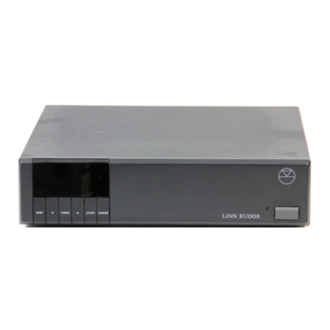
Linn Kremlin User manual

LINN KREMLIN
OWNERS MANUAL

2
IMPORTANT SAFETY INFORMATION
Explanation of symbols used in this manual and on the product:
This symbol is intended to alert the user to the presence of un-insulated
dangerous voltages within the enclosure of sufficient magnitude to cause
electricshock.
This symbol is intended to alert the user to the presence of important
maintenance and servicing information in the instruction and service
manuals.
CAUTION
TOREDUCETHERISKOFELECTRICSHOCKDONOTREMOVETHECOVER.
NOUSERSERVICEABLEPARTSINSIDE.
REFERSERVICINGTOQUALIFIEDSERVICEPERSONNEL.
WARNING:SHOCKHAZARD. DONOTOPEN.
AVIS:RISQUEDECHOCELECTRIQUE.NEPASOUVRIR.
CAUTION:REPLACEFUSEWITHSAMETYPEANDRATING.
ATTENTION.UTILISERUNFUSIBLEDERECHANGEDEMEMETYPE.
DISCONNECTSUPPLYCORDBEFORECHANGINGFUSE.
ATTENTION.DEBRANCHERAVANTDEREMPLACERLEFUSIBLE.

3
MAINS PLUGS
Thisapplianceissuppliedwithanon-rewireablemainsplugfortheintendedcountry.
ReplacementmainsleadscanbeobtainedfromyourLinnretailer.
Shouldyouneedtochangetheplugpleasedisposeofitcarefully.
Aplugwithbaredconductorsisdangerousifengagedinalivesocket.
TheBrownwiremustbeconnectedtotheLive(Line)supplypin.
TheBluewiremustbeconnectedtotheNeutralsupplypin.
TheGreen/YellowwiremustbeconnectedtotheEarth(Ground)supplypin.
Pleasecontactyourretaileroracompetentelectricianifyouareinanydoubt.
GENERAL SAFETY INSTRUCTIONS
1. Read Instructions. Read the safety and operating instructions before operating the
appliance.
2. RetainInstructions. Retainthesafetyandoperatinginstructionsforfuturereference.
3. Heed Warnings. Observe all warnings on the appliance and in the operating
instructions.
4. Follow Instructions. Followailoperatinganduseinstructions.
5. Waterand Moisture. Do notuse the appliancenear water, forexample near abathtub,
washbowl,kitchensink,laundry tub, in a wet basement or near a swimming pool and
thelike.
6. Carts and Stands. Use only with a cart or stand that is recommended by the
manufacturer.
6a. An appliance and cart combination should be used with care, Quick stops,
excessiveforceandunevensurfacesmaycausetheapplianceandcarttooverturn.
7. Wall or Ceiling Mounting. Mount to a wall or ceiling only as recommended by the
manufacturer.
8. Ventilation. Site the appliance so that its location or position does not interfere with its
proper ventilation. For example the appliance should not be situated on a bed, sofa,
rug or similar surface that may block the ventilation openings.' or placed in a built-in
installation such as a bookcase or cabinet that may impede the flow of air through the
ventilationopenings.
9. Heat. Site theappliance away from heat sources such as radiators, heaters, stoves or
otherappliances(includingamplifiers)thatproduceheat.
10. PowerSources. Connect the applianceto a powersupply only ofthe type describedin
theoperatinginstructionsormarkedontheappliance.
11. Grounding or Polarization. Do not defeat the precautions taken to ground or polarize
thesupplytotheappliance.
12. Power Cord Protection. Route power cords so that they are not likely to be walked on
or pinched by items placed upon or against them, paying particular attention to cords
atplugs,powersocketsandatthepointwheretheyexitfromtheappliance.

4
13. Protective Attachment Plug. As a safety feature the product is equipped with an
attachment plug containing overload protection. See the instruction manual about
resetting or replacing the plug. Should the plug need replacing ensure that a
replacementisusedwhichhasthesameoverloadprotectionastheoriginal.
14. Cleaning. The product should be cleaned only as recommended by the
manufacturer.
15. Powerlines. Anoutdoorantennashouldbelocatedawayfrompowerlines.
16. Outdoor Antenna Grounding, If an outdoor antenna is connected to the tuner/receiver
ensurethatthe antenna system isgrounded to provide someprotectionagainst voltage
surgesandstaticbuildup.
In the USA see articIe 810 of the National EIectricaI Code ANSI/NFPA 70 concerning
installationrequirements.
17. Non-use periods. Unplug the power cord from the outlet if the product will be unused
foralongperiodoftime.
18. Objectsandliquidentry. Takecarenottoletobjectsorliquidsfallintotheproduct.
19. Damagerequiringservice. Theproductshouldbeservicedbyqualifiedpersonnelif:
a) thepowercordorplughasbeendamaged.
b) objectsorliquidhavefallenintotheproduct.
c) theproducthasbeenexposedtorain.
d) the product does not appear to operate normally or exhibits a marked change in
operation.
e) theproducthasbeendroppedortheenclosuredamaged.
20. Servicing. Don't attempt to service the product beyond that described in the operating
instructions. Allotherservicingshouldbereferredtoqualifiedservicepersonnel.
UK USERS PLEASE READ THIS IMPORTANT SAFETY INFORMATION.
FUSE REPLACEMENT
Thisapplianceisfittedwithanon-rewireable 13 Amp mains plug. The plug contains a
5 Ampfuse.
Ifthefusehasblownitcanbereplaced
a) pullouttheredfusecover/carrier.
b) removeanddisposeoftheblownfuse.
c) fit a new 5 Amp BS1362 approved fuse into the carrier and push the carrier back into
theplug.
Always ensure the fuse cover is fitted. If the fuse cover is missing do not use the plug.
Contact your Linn retailer to obtain a replacement fuse cover. Fuses are for fire
protectionanddonotprotectagainstelectricshock.

5
MAINS PLUG REPLACEMENT
Should your mains plug need replacing and you are competent to do this proceed as
follows. IfyouareindoubtcontactyourLinnretaileroracompetentelectrician.
a) Disconnect the plug from themainssupply.
b) Cut off the plug and dispose of it safely. A plug with bared conductors is dangerous if
engagedinalivesocket.
c) Onlyfita13AmpBS1363Aapprovedplugwitha5Ampfuse.
d) The cable wire colours or a letter will be marked at the connection points of most
qualityplugs.
Attachthewires securely to their respectivepoints. TheBrownwire must go totheLive
pin, the Blue wire must go to the Neutral pin and the Green/Yellow wire must go to the
Earthpin.
e) Beforereplacingtheplugtopensurethat the cable restraint is holding the outer sheath
ofthecablefirmlyandthatthewiresarecorrectlyconnected.

6
USIC is very important for people. It stimulates the imagination, helps
them relax, can change their mood, and of course provides entertainment
andpleasure.
A good hi-fi works well enough to deliver these benefits. It also helps you appreciate
musicyouneverthoughtyouwould.
At Linn we devote our energy to improving standards of music reproduction, because
weknowthatthebetterthesoundthemoreyou'llenjoymusicathome.
Theadditionof any Linn componentwillimprovethe sound quality ofyoursystem. Linn
has a policy of continuously improving its equipment allowing customers to retro-fit
mostproductupgrades.
M

7
NTRODUCTION The Linn KREMLIN Tuner combines uncompromising audio
performancewitheaseofuse.
The KREMLIN is controlled by a microprocessor and is principally operated by
remotecontrol. Allremotecontrolfunctionscanheexecutedfromthefrontpanel.
Several different tuning methods are provided including manual tuning, automatic
scan tuning and preset memory tuning. There are eighty preset memories. The tuning
mode, signal strength and mono/stereo status are shown on the integral LED display.
The buttons on the front panel allow control of all tuner functions, whilst the addition of
thenumeric keypad onthe remote control allows directentry of thetuning frequency or
presetnumber.
Like any tuner, the KREMLIN will perform at its best when used with a good quality
aerial. Pleasereadthesectiononaerialinstallation.
I

8
INSTALLATION Unpacktheunitandretainthepackingforfuturetransportation.
KREMLINTunerUnit
MainsLead
Owner'sManualandRegistrationCard
2xSinglePhono-PhonoLeads
1xDualPhono-XLRLead
2xF-typeaerialconnector
SpareFuse
WARNING Usetheearthedmouldedmainsloadsupplied. Neveruseanunearthed
plugoradaptor.
WARNING
THIS APPLIANCE MUST BE EARTHED
IMPORTANT
Thewiresinthismainsleadarecolouredinaccordancewiththefollowingcode:
Green-and-yellow: Earth
Blue: Neutral
Brown: Live
As the colours of the wires in the mains lead of this appliance may not correspond with
thecolouredmarkingsidentifyingtheterminalsinyourplug,proceedasfollows:
The wire, which is coloured green-and-yellow, must be connected to the terminal that
is marked with the letter E, or the earth symbol, or is coloured green or green-and-
yellow.
The wire, which is coloured blue, must be connected to the terminal that is marked
withtheletterNoriscolouredblack.
The wire, which is coloured brown, must be connected to the terminal that is marked
withtheletterLorcolouredred.
CONTENTS

9
AERIALINSTALLATION The installation of a high quality aerial system is essential if
the best possible performance is to be obtained from the KREMLIN tuner. However,
the type of aerial system required for your location depends on a number of factors
including the power and siting of transmitters, the proximity of hills and tall buildings
and the presence of local interference sources. In some areas a high gain, highly
directional aerial will be required to reject interference sources. Where there are
transmitters in different directions, an aerial rotator may be useful. For some buildings
it may be illegal or impractical to erect a large outdoor aerial and therefore a high
qualityindooraerialmustsuffice.
For the best advice on an installation to meet the requirements in your area, we
recommend that you contact a local, reputable aerial installer. Your nearest Linn
dealershouldbeabletosuggestsuitablecompanies.
WARNING The tuner and the preamplifier must be switched off before connecting or
disconnectinganyoftheplugsontherearpanel.

10
TheKREMLINtunerhasconnectorsforbothanaerialinstallationandacablesystem:
AERIAL CONNECTION The aerial connector on the KREMLIN tuner is a standard
co-axial F-type. If the lead from your aerial is fitted with this type of plug, simply screw
theplugintothesocketonthetuneruntiltheconnectionissecurebutnotovertight.
If your aerial lead does not have an F-type plug, remove the existing plug from the lead
andfittheplugsuppliedasshownbelow:
Remove19mmoftheoutersleevefromtheendofthecable.
Remove13mmofthecoppershroudandinnersleeve
fromtheendofthecable.
Fold back the copper shroud over the outer sleeve and twist it
roundinaclockwisedirection.
Remove the section of the inner sleeve back to 2mm from the end
ofthecoppershroud.
Insert the cable into the 'F' type connector whilst twisting the connector in a clockwise
direction,untiltheconnectoristight-donotovertighten.
The KREMLIN tuner can power an external aerial amplifier should this be required in
areas of poor signal reception. For details of how to switch on the internal power
supply,pleaseseetheUSERSELECTABLEOPTIONSsection.
NOTE An aerial amplifier should never be used as a substitute for a good aerial
installation.
CONNECTION

11
CABLE CONNECTION The cable connector is a standard co-axial F- type. The
electrical specification of this input is identical to that for the aerial input so that a
secondaryaerial,ratherthanacablesystem,canbeconnectedifrequired.
AUDIO CONNECTIONS The KREMLIN has two identical stereo line outputs to
enableconnection to boththe preamplifier of a mainsystem and thedistribution unit of
amulti-roomsystem,withouttheneedforadaptercables.
Connect OUTPUT A LEFT to the left tuner input of the preamplifier and OUTPUT A
RIGHT totherighttunerinputusingthephono-phonointerconnectleadsprovided.
If required, connect OUTPUT B LEFT and RIGHT tuner inputs to the left & right
Tuner inputs of a multi-room system using high quality phono-phono interconnect
leads.

12
REMOTE IN / OUT CONNECTIONS The wired remote in and out facility on the
KREMLINisdesignedforuseinadistributedsystem(Knekt)whichmakespossiblethe
remoteoperationofvariousLinnproductsthroughoutyourhome.

13
OPERATION Connectthemains lead to the KREMLINandpressthe power button. A
greenlightwillimmediatelyappearnexttothebutton.
Two small dashes will appear on the display and after a short delay, the display will
show the setting at which the tuner was last used. The KREMLIN will then operate at
thelastusedfrequency.
Opening the door beneath the LED display reveals the control buttons. If the display
showstwodashes,itwillbecomeactivewhenthedoorisopened.
NOTE Twenty seconds after the last operation the display will turn off (show two
dashes).
Toswitchoffthetuner,pressandreleasethepowerbutton.

14
Toselecteithertheaerialorthecableinput,pressthe AERIAL button(orthe0button
on the remote control handset). When the aerial is selected, the display shows the
legendAERIAL.
Toshowthetunedfrequency,pressthe TUNE button. The display shows the legend
MHzandthefrequencyasafourorfivedigitnumber.
To tune up or down the band, press the [ + ] or [ – ] button. A single press on the
button alters the frequency in 10KHz intervals. Holding the button pressed causes the
tuningtochange continuously with thetuning rate gradually increasing.Whena station
is detected, the tuning speed is reduced so that the programme may be heard. The
tuning indicator has two arrows and one square symbol. When off-tune the arrows
indicate the direction of tuning required to fine-tune the station. When on-tune, the
squaresymbolisshownbrightlyandthetwoarrowsaredimmed.
Toselectscantuning,pressthe SCAN button.ThedisplayshowsSCAN.
Toscan upor down the band, press C or0 respectively. Thedisplay changes to show
thefrequency(in MHz) counting up ordownandone of the tuningindicatorarrowsis lit
toshowthedirectionofscanning. Duringscanning,theaudioismuted.
When a station is detected, the display stops counting, showing the frequency of the
station,andtheaudioisun-muted. Ifthe [ + ] or [ – ] button is still pressed, the scan
direction arrow flashes and after five seconds scanning continues. Otherwise
scanningstopsandaftera short time the display reverts to SCAN. The scan direction
arrowisshownasareminderofthepreviousscanningdirection.
The operation of the scan function can be changed (see user selectable options) so
that as each station is found, it is played for five seconds, then scanning resumes
automatically. During the five second audition period the scan direction arrow flashes.
Whenthe desired station isfoundstop the scanning bypressingthe SCAN button.
Scanningcanbestoppedatanylimeby pressing SCAN.
AERIAL
TUNE
SCAN

15
To store a tuned frequency as a memory preset, press the STORE button. The
display shows the number of the lowest empty preset memory. For example, preset 7
would be shown as St 7. If desired, select another preset number by pressing the [ + ]
or [ – ] button. If a .appears in the display (eg. St .7), the selected preset already has a
frequency stored. To store the current frequency in the selected preset number, press
STORE again.
In addition to the frequency, the preset memory stores the RF input ( AERIAL or
CABLE)selectedandtheMONO/STEREOstatus.
To show the preset memory number in use, press the [ PRESET button. The display
shows the number of the preset memory containing the current frequency. For
example preset 5 would be displayed as P 5. If no preset contains this frequency, the
display shows P. If all of the presets are empty, the display shows P -. Step up or down
throughthepresetsbypressingthe [ + ] or [ – ] button. Unused presets are skipped.
Toclear a presetmemory, press andholdthe PRESET button untilClr appears in the
display.
To clear all of the presets, first switch off the tuner. Press and hold down the PRESET
button. Switch on the power (still holding the button). After a short time the display will
show Clr. Keep the I ~ button pressed until the preset numbers also appear on the
display. The button may then be released. When all presets have been cleared,
normaltuneroperationwillberesumed.
The autostore facility combines the operations of the scan and store functions by
scanning the band from the lowest frequency to the highest, whilst automatically
storingstationsinsuccessivepresetmemoriesastheyarefound.
To initiate the autostore function, enter the store mode (by pressing STORE , as
above). Choosethepresetnumberinwhichthefirststationwillbestoredbyusingthe
[ + ] or [ – ] button. Pressandhold downthe STORE button again until AS appears
in the display. As each station is found, it will be played for five seconds before it is
stored and scanning is resumed. If it is desired not to store a particular station, press
the[ + ] button during the five second audition period to resume scanning.
STORE
PRESET
AUTOSTORE

16
NOTE The stations that have previously been stored in presets will be skipped by the
autostorefunction.
Theautostore function is terminated when either the top of the tuning range has been
reached or the highest numbered preset has been filled. The function can be
terminatedby pressing PRESET , TUNE , or SCAN .
Pressthe SIGNAL button to display the signal strength of the current frequency. (This
function is blocked when in store mode). In this mode, the tuning can be adjusted by
pressingthe [ + ] or [ – ] button in the same way as for the tune mode. After a time,
thesignalstrength mode is cancelledand the tuner revertstothemanualtuningmode.
The control of the audio muting and the detection of stations in the scanning and
autostore functions is determined by the mute/scan threshold. This is preset at the
factory, but can be altered by the user to allow very weak stations to be heard or to
eliminateallbutthestrongeststationsduringscantuning.
To display and alter the threshold, first enter the signal strength mode by pressing
SIGNAL . Release the button, then press it again and hold it until the display shows
‘th’ and a number corresponding to the threshold. Adjust the threshold using [ + ] or [
– ] button. The threshold mode will timeout automatically, or may be terminated by
pressing SIGNAL , PRESET , STORE , TUNE or SCAN .
Although the tuner automatically blends the stereo signal to mono at very low signal
strengths (to reduce noise), mono operation can be forced at any time by pressing the
MONO button. The legend MONO will appear on the display. To return to normal
operation,press the MONO button again. In normal operation, the STEREO legend
willbeshownifastereobroadcastisreceived.
SIGNAL
MUTE/SCANTHRESHOLD
MONO

17
OPERATION FROM REMOTE CONTROL HANDSET The TUNE, SCAN,
PRESET, STORE, [ + ], [ – ], SIGNAL and MONO buttons on the handset are
identical in operation to those on the front panel. In addition to these buttons, the
handset provides a numeric keypad, 0 - 9. This can be used to enter directly the tuning
frequencyorthepresetmemorynumber.
DIRECT ENTRY OF TUNING FREQUENCY To enter the frequency, first press the
TUNE button. Press the keypad buttons to enter the desired frequency. After the first
digit has been entered, the display shows three or four dashes ( – ) to indicate how
many more digits must be entered. When the complete frequency has been keyed in,
the display flashes to show that the frequency has been accepted. The tuner then
muteswhileittunestothenewstation.
If the first digit entered is not within the valid tuning range of the KREMLIN, the display
showsfourdashes( - - - - ) and then reverts to the original frequency. After the first valid
digit, if subsequent entries would result in a frequency outside the tuning range, each
digitentryischangedautomaticallytoresultinavalidfrequency.
Ifanerrorismadeinkeyinginthefrequency,pressthe TUNE buttontocleartheentry,
then either re-enter the correct digits or press TUNE again to return to the original
frequency.
DIRECT ENTRY OF PRESET NUMBER To enter the preset memory number, first
press the PRESET button. To select preset numbers from 1 to 9, briefly press the
buttons 1to 9on the handset. For preset numbers 10 to 80, press and hold the
buttonfor the firstdigit until adash( – ) appears in the display (and the audio is muted),
then press the button for the second digit. If the selected preset memory is empty the
displayshowsEforashorttime.
Tostorethetunedfrequencyinapresetmemory,firstpressthe STORE button. Enter
thepreset number asdescribed above, thenpress STORE again.
RF INPUT SELECTION Press the 0button to switch between the AERIAL and
CABLE inputs.

18
USERSELECTABLEOPTIONS The user can customise operational features of the
tunertosuitpersonalpreferences.
To do this, enter the user function mode. First, switch off the tuner. Press and hold
eitherthe MONO orthe SIGNAL button and switch on the power. After a short time,
thedisplaywillshowU.KeepthebuttonpresseduntilthedisplaychangestoU1.
Tostepupordownthroughtheuserfunctions,pressthe MONO or SIGNAL buttons
respectively. The user functions are displayed as U1 - U5. The status of each function
isshownbythe number on therightofthe display. To step throughtheoptionsfor each
function, usetheaor0button.
The table below lists the options for all of the user modes and is followed by a more
detaileddescription. Alloptionsaresetto0atthefactory.
U1 0displayturnsoffautomatically
U1 1displayremainsconstantlyilluminated
U2 0maintainthecurrentdisplaymode
U2 1reverttothetunedisplaymode
U2 2reverttothescandisplaymode
U2 3reverttothepresetdisplaymode
U3 0remoteamplifierpowerisOFF
U3 1remoteamplifierpowerisONwhentheAERIALinputisselected
U3 2remoteamplifierpowerisONwhentheCABLEinputisselected
U3 3remoteamplifierpowerisONforbothAERIALandCABLEinputs
U4 0scanningisstoppedwhenastationisdetected
U4 1scanningresumesfivesecondsafterastationhasbeendetected
U50 REMOTE OUT socketisdrivenbyfrontpanelremotesensor
U51 REMOTE IN socketisnotdrivenbythefrontpanelsensor
USERFUNCTION1(U1)Option 0 turns off the display twenty seconds after the last
buttonpress. SelectOption1tohavethedisplayconstantlyilluminated.
USERFUNCTION2(U2)Option 0 maintains the display of the last operation. The
displaywilldefaulttoTUNE,SCANorPRESETmodebychangingtoOption1,2or3.
USER FUNCTION 3 (U3)Option 0 turns off the power supply for a remote aerial
amplifier. Select options 1, 2 or 3 only if it is required to power an external amplifier.
Option 1 turns on the power supply when the AERIAL input is selected. Option 2 turns
ADVANCEDFEATURES

19
on the power supply when the CABLE input is selected. Option 3 turns on the power
supply for either input. For details of the power supply voltage and maximum current,
seetheSPECIFICATIONSsection.
USER FUNCTION 4 (U4)Option 0 causes the scanning to stop when a station is
detected. When Option 1 is selected scanning pauses for five seconds when a station
isdetected,thenresumesautomatically.
USERFUNCTION5(U5)Option 0 connects the signal from the front panel remote
control sensor to the REMOTE OUT socket. This allows the KREMLIN to act as a
remote control receiver for other Linn equipment, which may be in a concealed
location. In some installations this facility may not be required. If option 1 is selected
the REMOTE IN socket is driven only by signals connected to the socket.
Toexit the user functionmode, press any ofthebuttons TUNE , SCAN , PRESET or
STORE , or wait for the mode to timeout approximately twenty seconds after the last
buttonpress.
To restore all of the User Functions to the original factory setting, first switch off the
tuner,pressandholdthe [–]buttonandswitchonthepower.Whenthedisplayshows
INIT,thebuttonmaybereleased. AllUserOptionsarethensetto0.

20
TURNTABLES Forbestresultsaturntableshouldbeplacedonasmall,light,rigid
tableoralternativelywallmountedonalight,rigidshelf.
POWERSUPPLIES Take care not to position too close to signal leads, turntable or
pre-amplifier.
AMPLIFIERS Pre and power amplifiers may create hum if positioned too close
together. Experiment by moving the components when the system is on but not playing
music.Itisbesttoturnthevolumedownwhilstactuallymovingthecomponents.
LOUDSPEAKERS Loudspeakers should be positioned according to manufacturers'
instructions. They should be mounted on rigid stands, and not subject to any rocking
movement. All Linn speakers except NEXUS and HELIX are designed to be placed
closetothewall.
CLEAN CONTACTS It is important that the electrical contacts in a hi-fi system are
kept clean and mechanically sound. Unplugging and re-plugging all the connectors
occasionallywilleffectivelycleancontacts.
WARNING Thisshouldbecarriedoutafterthemainssupplyhasbeenswitchedoff.
INTERCONNECT LEADS Correct cables should be used. We recommend good
quality copper cable for interconnect leads and advise 4mm2multicore copper cable,
suchasLinnK20,forspeakerleads.
Your Linn dealer can supply high quality interconnects for linking all your hi-fi
components.
GENERALSYSTEMINSTALLATION
Table of contents
Other Linn Tuner manuals