LION 6 User manual

EMERGENCY
RESPONSE
GUIDE
THIS GUIDE IS INTENDED FOR FIRST RESPONDERS AND CERTIFIED RESCUERS.
High-voltage batteries are the only energy source for the propulsion of the .
Always act as if the high-voltage system is activated. The high-voltage system might
be active even when no sound is emitted from the vehicle.

2

3
Emergency Response Guide
// CONTENT
CONTENTS.........................................3
Legal notice ..........................................4
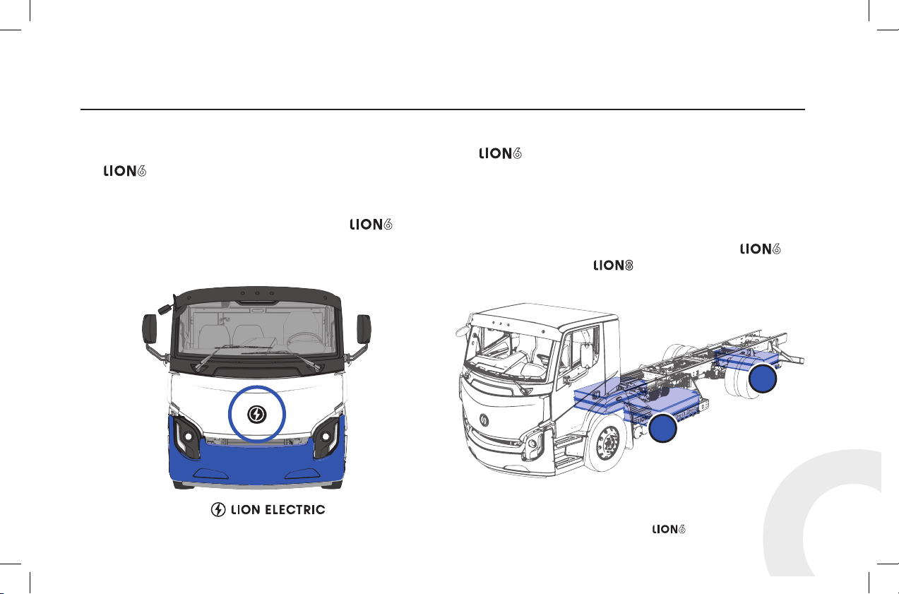
IDENTIFYING THE VEHICLE ........................5
Logo ................................................5
Batteries location .....................................5
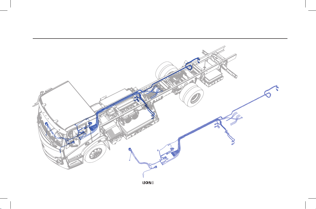
HIGH-VOLTAGE COMPONENTS ................... 6
Schematics ..........................................6
High-voltage cables routing .............................7
Warning labels........................................9
ACCESSORIES COMPARTMENT ...................10
TURNING OFF THE VEHICLE ......................11
Turning o the vehicle.................................11
DISABLING THE HIGH VOLTAGE...................12
Disabling the high voltage..............................12
CRASH SAFETY IMPACT DETECTOR ...............13
FIRE AND WATER IMMERSION ....................14
ACCESSES ........................................15
Opening the front hood ...............................15
Tilting the cab .......................................16
REINFORCEMENTS AND LIFTING THE VEHICLE ...18
Reinforcements ......................................18
Lifting the vehicle.....................................19
TOWING THE VEHICLE ........................... 20
Releasing the parking brakes ...........................20
Removing wheel axle half shaft .........................22

4
LEGAL NOTICE
The information contained in this document is subject to change
without notice. This document is intended for customers of The
Lion Electric Company and for first responders. No part of this
document may be reproduced or transmitted in any form without
the prior written permission of The Lion Electric Company.
The Lion Electric Company cannot be held liable for any errors
in this document, or for any damages that may result from the
use of this document or the information contained.
Intellectual property rights related to this document and the
product described are exclusive to The Lion Electric Company
and are protected by applicable intellectual property legislation.
Copyright © The Lion Electric Company 2020.
All rights reserved.

5
Emergency Response Guide
// IDENTIFYING THE VEHICLE
Identification
The can be idendified by the Lion Electric logo located
at the centre front of the hood.
The logo can also be found throughout the cabin and on
several chassis components. There also may be
decals near the bottom of the cabin doors.
The can be equipped with two to six batteries. In its
fullest battery configuration:
• four batteries are located between the front and the rear axle,
• two batteries are located behind the rear axle.
The Lion Electric builds two types of heavy electric trucks which
can be quickly dierentiated by their rear axles. The has a
single rear axle while the has a rear tandem (double) axle.
Figure 1 ― logo Figure 2 ― Batteries locations
1
2

6
// HIGH-VOLTAGE COMPONENTS
Schematics
Figure 3 ― Identification of high-voltage components (side view)
1
2
3
4
5
6
7
8
9
10
10 1011 12 13

7
Emergency Response Guide
// HIGH-VOLTAGE COMPONENTS
Figure 1 ―
Table 1 ― Identification of high-voltage components
Nº Identification Nº Identification Nº Identification Nº Identification
1AC compressor 5DC junction box
8DCDC converter
(2 units) 11
BTMS compressor
(battery thermal
management system)
2Electric defroster/heater 6Air brake compressor
3Charging port
7High-voltage distribution
unit (HVDU)
9BCI20 (charger inverter) 12 Motor
4Hydraulic pump 10 Batteries (Lithium-Ion) 13 Drive
Figure 4 ― Identification of high-voltage components (top view)

8
// HIGH-VOLTAGE COMPONENTS
High-voltage cable routing
Figure 5 ― High-voltage cable routing

9
Emergency Response Guide
// HIGH-VOLTAGE COMPONENTS
Label Meaning
CAUTION! High-voltage battery
Incorrect handling may cause injury
• High voltage
• Risk of explosion
• Risk of chemical burns
and eye injuries
Battery specifications
You are in the presence of
hazardous voltage.
Danger high voltage
Certain components must be
disconnected before servicing.
Please see the Disabling the high
voltage section of this document.
Label Meaning
DO NOT activate.
Work on high-voltage systems in
progress.
CAUTION! Hazardous voltage
CAUTION! High-voltage parts
Before working on the vehicle, follow the
procedure described in the Disabling the
high voltage section of this document.
HAZARDOUS VOLTAGE!
Risk of electrocution
Shut o the high-voltage components.
CAUTION! High voltage
The voltage behind this panel is
potentially fatal. Access is restricted to
qualified personnel.
Table 2 ― High-voltage equipment warning labels
Warning labels

10
// ACCESSORIES COMPARTMENT
Accessories compartment
The accessories compartment is located on the left side of the
, behind the cabin. Its primary function is to hold the
low-voltage components. The low-voltage components
function on both 12V and 24V. No high voltage is running
through the master disconnect switch. The master disconnect
switch deactivates the high voltage battery contactors.
The following can be found in the accessories compartment:
• Master disconnect switch (low and high voltage)
• Two low-voltage batteries
• Fuse box
Figure 6 ― Accessories compartment

11
Emergency Response Guide
// TURNING OFF THE VEHICLE
Turning o the vehicle
1. Press on the brake pedal and put the vehicle in neutral by
pressing on the Nrocker switch located on the dashboard
(Figure 7).
2. Apply the parking brake by pulling the yellow diamond-
shaped button located on the dashboard (Figure 8).
3. Turn o the ignition switch and remove the key (Figure 9).
Figure 9 ― Ignition switch
ACC
OFF
ON
START
Figure 7 ― Gear selector
PUSH
PULL
APPLY
RELEASE
Figure 8 ― Parking brake air-supply control

12
// DISABLING THE HIGH VOLTAGE
Disabling the high voltage
The vehicle’s ignition must be turned o prior to disabling the
high voltage (See page 11).
1. Check the charging receptacle located in the passenger
steps to make sure that the vehicle is NOT connected. If
the vehicle’s charging receptacle is connected, remove the
connector.
2. Open the accessory compartment located behind the
driver’s (left) front wheel. Locate the master disconnect
switch and turn it o. Turning o this switch deactivates the
low and high voltage. (See page 10)
3. Double cut the battery cables on both low-voltage batteries
located in the accessories compartment. (See page 10)
DANGER
Do NOT cut any orange-coloured high-voltage cable wires.
Figure 10 ― Master disconnect switch location
Figure 11 ― Two low-voltage batteries

13
Emergency Response Guide
DANGER
ALWAYS assume the high voltage is active.
Follow the procedure to disable the high voltage, even if the
crash safety detector appears to have been triggered.
// CRASH SAFETY IMPACT DETECTOR
Crash safety impact detector
For the safety reasons, the high-voltage safety disconnect
switch is linked to the ’s impact sensor. When the
sensor reads an impact between 8 g and 30 g, it will instantly
deactivate the high-voltage circuits.
Figure 12 ― Location of impact sensor

14
// FIRE AND WATER IMMERSION
Fire extinguishment of high-voltage batteries
If there is a crack in the batteries due to an impact, an
inflammable and corrosive electrolyte solution may leak.
If there is a fire in the batteries, use a lot of water to cool down
the batteries or CO2. The batteries will not explode.
Depending on the availability, other extinguishing agents (fire
extinguishing foam, extinguishing powder) may also be used.
As common in firefighting, complete personal protective
equipment (PPE) including self-contained breathing apparatus
(SCBA) must be used.
If there a fire that is not emerging from the high-voltage
batteries, it can be treated using typical vehicle firefighting
procedures.
Submerged vehicle
A that is submerged in water will not present the risk
of electrocution since the high-voltage batteries are isolated
from the vehicle chassis.
Treat a partially or fully submerged as any other
vehicle and use the appropriate personal protective
equipment (PPE).
Once the vehicle is removed from water, disable the high
voltage using the procedure listed in this manual (See page 11).

15
Emergency Response Guide
// ACCESSES
Opening the front hood will give you access to the consumable
materials of the vehicle.
Opening the hood:
1. Stand in front of the vehicle and locate the release latches
(figure 13) on each side of the front of the hood.
2. Pull both levers at the same time.
3. Lift the hood and locate the handle located in the centre
(figure 14), at the far edge of the hood.
4. Use the handle to lift the hood.
5. Push on both arms of the safety mechanism (figure 15)
to lock the hood in the open position.
Figure 13 ― Location of hood latches
Figure 14 ― Location of handle under the hood
Figure 15 ― Location of hood safety mechanism

16
// ACCESSES
Tilting cab mechanism
Under normal circumstances, the uses a hydraulic
system to tilt the cab. This system uses an electric motor
to activate the hydraulic pump. However, if the vehicle’s
low-voltage power source has been disabled, you can
still tilt the cabin.
To manually operate the cab tilting pump:
1. Check to make sure that the vehicle’s high-voltage circuits
have been turned o, or turn them o (See page 12).
2. Apply the parking brake and put the gear selector in
Neutral (See page 11).
3. Lift the front hood (See page 15) and remove the tubular
lever for the manual pump from under the hood (Figure 18).
4. Insert the tubular lever on the side of the pump (Figure 19).
5. Place the selector valve on the hydraulic pump in the CAB
RAISE position.
WARNING
The hydraulic cab tilt system is a cab lifting, NOT a cab
holding device. Before going under a raised cab, ALWAYS
engage the mechanical cab holding device.
Figure 16 ― Hazard warning label
WARNING / ATTENTION
CRUSH HAZARD
FALLING CAB MAY INJURE OR KILL
RISQUE D’ÉCRASEMENT
LA CHUTE DE LA CABINE PEUT
CAUSER DES BLESSURES OU LA MORT

17
Emergency Response Guide
// ACCESSES
6. Activate the pump by using the tubular lever. The latch
hooks will release and the cab will rise.
7. As the cab approaches top dead centre (TDC), pump
slowly. When the cab goes over TDC, stop pumping. The
cab will free fall slowly to full tilt.
Figure 17 ― Hydraulic cab pump mechanism
Figure 18 ― Tubular lever under the hood
To lower the cab, follow the same steps with the selector valve
in the CAB LOWER position.
Figure 19 ― Tilting cab mechanism

18
// REINFORCEMENTS AND LIFTING THE VEHICLE
Reinforcements
The has a reinforced cabin to protect in case of an impact.
Suitable tools must be used to cut or crush these areas.
Figure 20 ― Reinforced cabin

19
Emergency Response Guide
// REINFORCEMENTS AND LIFTING THE VEHICLE
Lifting the vehicle
If lifting the vehicle is necessary, use the following practices:
• Proper jacking procedures and basic safety measures
must be observed to ensure the safety of personnel while
performing duty under the vehicle.
• Always check the serviceability of any lifting equipment
prior to use.
• Ensure that the lifting equipment is of sucient strength
to handle the vehicle, and that the surface provides the
necessary firmness to support the weight of the vehicle
concentrated on the footprint of the jack.
• Park the truck on a flat, level surface of sucient firmness
to support the jack.
Lifting areas
• Place the jack securely under the axle at the spring or
suspension beam, nearest the tire/wheel.
• Place the jack securely under the frame rails.
WARNING
Do NOT lift the vehicle from under the batteries.

20
Figure 21 ― Rear axle parking brake
Figure 22 ― Rear axle parking brake release
Releasing the parking brakes
If all of the air has been evacuated from the pneumatic
system, it is possible to release the parking brakes by manually
compressing (caging) the spring brake actuator. Before
manually releasing parking brakes, chock the wheels to prevent
the vehicle from moving.
To manually release the spring brake:
1. Remove the dust plug from the parking brake chamber.
2. Remove the release nut and washer from the release bolt.
3. Slide the release bolt out of the holder.
4. Insert the compression screw assembly through the
opening in the rear of the spring chamber.
5. Turn the release bolt a quarter turn clockwise.
6. Using a wrench, turn the release bolt assembly nut until the
compression spring is 90–95 % caged.
7. Check to make sure the pushrod is retracting.
The spring brake is now mechanically caged.
// TOWING THE VEHICLE
Before attempting to tow the vehicle, you will need to release
the parking brakes.
Table of contents