Lipco UF 70 Setup guide

Translation of
Reversing harrow
UF 70 / 80 / 90 / 100
original instruction
Standard version
Gearbox right turning
Reversing Harrow
UF 70 L
Special edition
Gearbox left turning
LIPCO GmbH
Am Fuchsgraben 5b
D-77880 Sasbach
Tel.
+49 7841 6348-0
Fax
+49 7841 6348-300
E-mail
Web
www.lipco.com

Instructions
Reversing Harrow UF 70/80/90/100 _ 70L
2 - 28
110030-11-EN BA UF 70_80_90_100 UF 70 L / 29.06.2020
1. Introduction
Dear Customer,
We thank you for having chosen a LIPCO Reversing Harrow. We hope
that you will be happy with your choice.
In order that your LIPCO Reversing Harrow UF will serve you well for
many years, we ask you to pay close attention to the operating
instruction, which you will find in this manual. This will help you to
prevent breakdowns and accidents resulting from non-observance of
the operating instructions, for which our company will not accept
responsibility.
This Instruction and Maintenance Manual is to be considered as an
integral part of the machine itself and therefore it must always
accompany the machine when it is sold, even in the event of its sale
to third parties.
If you keep this manual in a safe place and in good condition, you -
and whoever must use the machine - will be able to have a complete
reference on hand at all times.
Note:
The illustrations, descriptions and specifications in this manual are not
binding. LIPCO reserves the right to make modifications without
notice.

Instructions
Reversing Harrow UF 70/80/90/100 _ 70L
3 - 28
110030-11-EN BA UF 70_80_90_100 UF 70 L / 29.06.2020
2. Contents Page
1. Introduction 2
2. Contents 3
3. Designated use 4
4. Warning signs attached to the machine 5
5. Safety regulations 6
6. Accident prevention 7
7. Design features 9
8. Preparation 11
9. Technical data 12
10. Connection to the engine-driven machine 13
11. Adjustment of working depth/roller adjustment 15
12. Working instruction (Release of overload clutch) 16
13. Maintenance 18
14. Replacement of the cutting blades 20
15. After use 21
16. Disposal after end of lifetime of the machine 21
17. Notices 22
18. Warranty 26
19. EC Declaration of conformity 27

Instructions
Reversing Harrow UF 70/80/90/100 _ 70L
4 - 28
110030-11-EN BA UF 70_80_90_100 UF 70 L / 29.06.2020
3. Designated use
The LIPCO Reversing Harrow UF, when connected to engine-driven
machines from 6,0 →10,0 kW, is designed to till and level the ground
in a single operation, thus preparing it for seeding.
Any other use for purposes other than those described here is not
according the designated use. Do not held the manufacturer liable for
damage resulting from such use; the risk for such use lies entirely with
the user.
Operating the unit within the limits of its designated use also means
following the instructions for operation, transport and maintenance
described by the manufacturer.
Persons who are familiar with the unit and informed about possible
risks must carry out any work, maintenance and repair on the LIPCO
Reversing Harrow UF!
Please observe the relevant accident prevention regulations as well
as the other generally recognized maintenance, safety, industrial
medicine and road traffic rules and instructions.
The manufacturer cannot be held liable for damage resulting from
unauthorized modifications of the LIPCO Reversing Harrow UF.

Instructions
Reversing Harrow UF 70/80/90/100 _ 70L
5 - 28
110030-11-EN BA UF 70_80_90_100 UF 70 L / 29.06.2020
4. Warning signs attached to the machine
Before starting operation, the personnel must have
read the operating and safety instructions and must
observe them.
Before commencing maintenance and repair work,
switch off the engine and pull the key.
With the drive switched on and the motor running,
maintain sufficient distance to rotating tools.
With the motor running, there is a risk of parts being
hurled away –maintain safety distance.
Do not reach into rotating tools.

Instructions
Reversing Harrow UF 70/80/90/100 _ 70L
6 - 28
110030-11-EN BA UF 70_80_90_100 UF 70 L / 29.06.2020
5. Safety regulations
The operation of machines containing rotating or moving tools always
bears risks. Please always follow the safety regulations:
•Before starting operation, the personnel must have read the
operating and safety instructions and observe them.
•Never remove or alter the safety devices!
•Do not touch rotating or moving parts!
•Secure the unit carefully before lying down beneath the unit for
repair or control purposes!
•Use the machine only in technically perfect condition!
•For maintenance work switch off the device!
•Maintain safety distance! (Take note of the danger sign on the side
of the machine)
•Let the work carry out only by people who are familiar with the unit
and are been informed about possible risks!
•Please observe the relevant accident prevention regulations as
well as the other generally recognized maintenance, safety,
industrial medicine and road traffic rules and instructions.
•The warnings and signs attached to the unit give important
information on safe operation; observing this instruction will ensure
your safety!
•Do not wear wide or loose clothes (e.g. scarves)!
•When working with the machine, you must wear safety shoes.

Instructions
Reversing Harrow UF 70/80/90/100 _ 70L
7 - 28
110030-11-EN BA UF 70_80_90_100 UF 70 L / 29.06.2020
6. Accident prevention
Most accidents that occur during work, maintenance or transport of a
machine are due to non-observance of the most elementary rules of
accident prevention.
It is, therefore, necessary that all licensed users (relatives, employees,
colleagues) read and observe the rules given below and written on the
adhesive labels of the machine itself:
•Turn off the engine of the engine-driven machine, before carrying
out any adjustments, maintenance or cleaning on the machine!
•Prior to any work on the machine, place the machine on level and
solid ground! When working with the unit lifted, always secure the
unit mechanically by means of adequate supporting elements!
•In order to achieve the highest possible performance of the LIPCO
Reversing Harrow, it must always be in perfect condition. Only well
trained people may carry out maintenance and repair. Spare parts
must at least comply with the technical requirements specified by
the manufacturer! Only use of LIPCO original spare parts will
guarantee this!
•Before each use, check screws and nuts, especially those of the
cutting blades and the drive, that they are firmly tight!
•Before starting up, please make sure that no people or animals
are in the vicinity!
•Take special caution when working alongside roads or pathways!
•Do not leave the machine running without supervision!
•During service or repair work, make sure that no one can start up
the machine accidentally!
•Do not wear wide or loose clothes (e.g. scarves)!
•Do not, for any reason, climb onto the machine during operation!

Instructions
Reversing Harrow UF 70/80/90/100 _ 70L
8 - 28
110030-11-EN BA UF 70_80_90_100 UF 70 L / 29.06.2020
•Never work without machine protection!
•Do not act with any objects on the machine during operation!
Instructions
Reversing Harrow UF 70/80/90/100 _ 70L
9 - 28
110030-11-EN BA UF 70_80_90_100 UF 70 L / 29.06.2020
7. Design features
The LIPCO Reversing Harrow, when connected to any type of engine-
driven machine from eight to 10 kW, is capable of tilling and levelling
the ground in a single operation, thus preparing it for seeding. The
LIPCO Reversing Harrow dugs stones, clods, old lawn, etc. into the
ground.
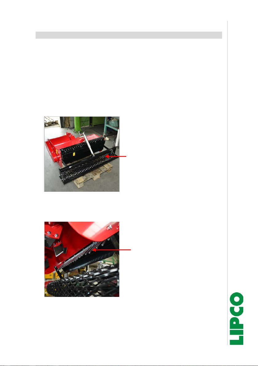
•LIPCO Reversing Harrow is equipped with a grid roller, which
makes it possible to adjust the working depth of the cutter and to
ram the earth. (Fig. 1)
Grid roller
Fig. 1
•The integrated rake pulverizes the earth smoothly. (Fig. 2).
Rake seen from the bottom
Fig. 2
Instructions
Reversing Harrow UF 70/80/90/100 _ 70L
10 - 28
110030-11-EN BA UF 70_80_90_100 UF 70 L / 29.06.2020
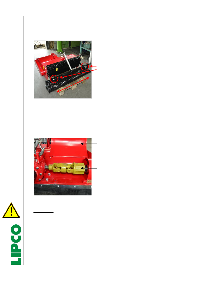
•The machine is also equipped with a lateral roller adjustment,
enabling to work right to the edge, for example on path borders.
Adjustable grid roller
Clamping studs for cage roller
adjustment
Fig. 3
•The LIPCO Reversing Harrow is equipped with an overload
coupling, a so-called star ratchet (Fig. 4). This will limit the torque
in case of overload. The noise produced in this process serves as
warning signal.
Protective hood on top of star
ratchet is open.
Star ratchet
Fig. 4
Attention!
When you hear a rattling noise of the locking body, turn-off the
power take-off shaft immediately!

Instructions
Reversing Harrow UF 70/80/90/100 _ 70L
11 - 28
110030-11-EN BA UF 70_80_90_100 UF 70 L / 29.06.2020
8. Preparation
•Make sure that the unit is in perfect working order and that all
safety devices are in place!
•Check the oil level in the angular gear! (See chapter "13.
Maintenance")
•Check the lubrication in the chain drive! Run the machine for a
short time, in order to distribute the grease evenly. (See chapter
"13. Maintenance")
•Check whether all screws are tightened, especially important are
the screws of the cutter blades and the drive flange!
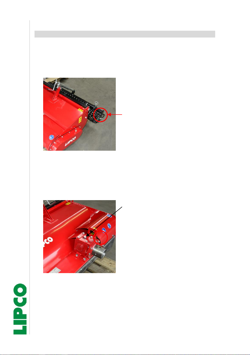
•Lubricate overload coupling (star ratchet Fig. 5) and universal joint
shaft of the drive prior to startup and then every eight working
hours.
•To do so, open the protective hood (Fig. 5).
Protective hood opened.
Lubricating nipple (3x)
Fig. 5

Instructions
Reversing Harrow UF 70/80/90/100 _ 70L
12 - 28
110030-11-EN BA UF 70_80_90_100 UF 70 L / 29.06.2020
9. Technical data
Type
Weight
(kg)
Required drive
power
(kW)
Number of
Discs / cutters
UF 70 L
120
6
5
10
UF 70
120
6
5
10
UF 80
150
8
6
12
UF 90
165
9
7
14
UF 100
175
10
8
16
Main dimensions
L
B
H
UF 70 L
1020
900
455
UF 70
1020
900
455
UF 80
1020
1080
455
UF 90
1020
1230
455
UF 100
1020
1320
455
The Reversing Harrow is designed for a maximum working depth
of 15 cm.
Remarks about noise and vibration:
The values for noise and vibration of this attachment unit will not
exceed the values of the engine-driven machine.
Working direction

Instructions
Reversing Harrow UF 70/80/90/100 _ 70L
13 - 28
110030-11-EN BA UF 70_80_90_100 UF 70 L / 29.06.2020
10.Connection to the engine-driven machine
Note:
In standard version, reversing harrow is equipped with rotation
gear.
As UF 70 reversing harrow is also available with an anti-clockwise
gear (version UF 70 L), make sure, when attaching reversing harrow
to the engine-driven machine, that both directions of rotation are
identical.
The direction of rotation of the reversing harrow must correspond to
the direction of rotation of the engine-driven machine, otherwise
malfunctions / damages will occur.
•Before attaching the machine-flange (Fig. 6) corresponding to the
type of engine-driven machine you have, it is recommended
spreading grease on the outer diameter of the machine hub (Fig.
6, Ref. B). Then insert the flange with its two threaded pins (Fig. 6,
Ref. C) and the two lock nuts. To attach the flange to the hub,
proceed as follows:
Fig. 6
•Screw the threaded pins in as far as possible and then unscrew
them by one turn. Tighten the lock nuts. After this operation, make
sure that the flange oscillates freely without squeezing or blocking.
•After having greased the connecting shaft (Fig. 4, Ref. D), insert it
on the machine shaft of the Reversing Harrow. When these steps
are complete, move the engine-driven machine close to the unit.
Ensure that the gearing of the connecting shaft engages correctly
A
B
C
E
D

Instructions
Reversing Harrow UF 70/80/90/100 _ 70L
14 - 28
110030-11-EN BA UF 70_80_90_100 UF 70 L / 29.06.2020
•with the power takeoff shaft of the engine-driven machine and the
flange has a centered contact with the engine-driven machine.
Then secure the connection between the engine-driven machine
and the unit.
Before beginning to work, lubricate drive flange on the lubricating
nipple (Fig. 6, Ref. E)!

Instructions
Reversing Harrow UF 70/80/90/100 _ 70L
15 - 28
110030-11-EN BA UF 70_80_90_100 UF 70 L / 29.06.2020
11.Adjustment of working depth/roller adjustment
•Adjust the working depth with the spindle (Fig. 5, Ref. B). It is
important, that the machine rest on its cage roller while working.
Spindle for working depth
adjustment
Fig. 7
•You can shift the cage roller of the LIPCO Reversing Harrow
sideward (Fig. 8) to enable driving right to the edge of enclosures
or walls. To shift the cage roller, loose the two clamping screws
(Fig. 8) shift the cage roller to the desired position and re-tighten
the two clamping screws again.
Cage roller adjustable
Clamping screws for roller
adjustment
Fig. 8

Instructions
Reversing Harrow UF 70/80/90/100 _ 70L
16 - 28
110030-11-EN BA UF 70_80_90_100 UF 70 L / 29.06.2020
12.Working instruction (Release of overload clutch)
Attention:
Note
the working direction!
Working against the specified working direction can cause heavy
damages on the machine, for which LIPCO denies any
responsibility!
Working direction –pulling,
See direction of arrow
Fig. 9
•The blades are by their shape and cutting position designed for
this working direction.
•Working against the prescribed working direction leads to an
overload of the cutters and drive, and can thus cause damage to
the machine.
•Simultaneously with non-observing the working direction, the
harrowing result will get worse.
•The LIPCO Reversing Harrow is equipped with an overload clutch
(star ratchet), which is pre-set at the factory. Do not change the
setting of the overload clutch.
The overload torque depends on the size of the machine.

Instructions
Reversing Harrow UF 70/80/90/100 _ 70L
17 - 28
110030-11-EN BA UF 70_80_90_100 UF 70 L / 29.06.2020
Troubleshooting:
If there is an overload –indicated by a ratcheting noise –turn off
the PTO immediately.
An overload can happen by:
- Too big stones in working area
- Other obstacles
- Jammed part in cutter area like stone, branch, root
Remove obstacle carefully from working area of turned-off
machine.
If there are generally too big stones or other obstacles in the
working area, then remove them manually prior to starting any work
with the LIPCO Reversing Harrow.
Instructions
Reversing Harrow UF 70/80/90/100 _ 70L
18 - 28
110030-11-EN BA UF 70_80_90_100 UF 70 L / 29.06.2020
13.Maintenance
In order to maintain the machine in good working condition, carry out
following steps:
•Grease the roller bearings on both sides (Fig. 10).
Bearing on both ends of grid
roller
Fig. 10
•Check the oil level in the angular gear (Fig. 8). Oil level 2-3 cm in
horizontal gear drive position. Make the first oil change after 30 to
50 operating hours. Further oil changes after every 200 operating
hours or once a year. Use gear oil SAE 90. (Amount of oil 0.3 L)
Oil filler neck to check oil level in
gearbox.
Fig. 11
•Tighten all cutting blade screws. Replace damaged screws
immediately (refer to chapter "14. Replacement of the cutting
blades"). Note: Always use the original steel nuts with fine pitch
thread.

Instructions
Reversing Harrow UF 70/80/90/100 _ 70L
19 - 28
110030-11-EN BA UF 70_80_90_100 UF 70 L / 29.06.2020
•Lubricate the drive flange once a month via the lubricating nipple
provided especially for this purpose and then turned once to allow
the grease to become distributed!
•Make sure it runs smoothly.
•Remove drive flange once a year, clean and regrease it.
•Lubricate the overload coupling (star ratchet) and universal joint
shaft of the drive every 8 operating hours and after a longer
standstill! (Fig. 12)
Protective hood opened.
Lubricating nipple (3x)
Fig. 12
•Check the level of lubricant in the chain drive via the corresponding
plug (Fig. 11). Make the check, when the machine has already
been running for a few minutes. This ensures that the grease has
warmed up and is distributed evenly. Then check the grease level
with a dipstick (grease level should be at least 5 cm, measured
from the lowest point of the chain case to ensure that the chain is
always sufficiently lubricated).

Instructions
Reversing Harrow UF 70/80/90/100 _ 70L
20 - 28
110030-11-EN BA UF 70_80_90_100 UF 70 L / 29.06.2020
Plug for grease level
check in chain box
Fig. 13
If necessary, add liquid gear grease (based on sodium bicarbonate
- type GP 00).
14.Replacement of the cutting blades
For replacing the cutting blades, secure the machine against
unintentional tilting! When working with the unit lifted, always ensure
mechanical protection by means of adequate supporting elements!
When replacing them, it is very important to maintain the blade
arrangement, especially the direction of the cutting edge. Mount the
blades in the cutting direction towards the supporting roller.
Note location of cutter blade
front side
Fig. 14
This manual suits for next models
4
Table of contents
Popular Tractor Accessories manuals by other brands

Toro
Toro 111-6032 installation instructions

Kubota
Kubota BX25 Deluxe ROPS Cab installation manual

Grouser Products
Grouser Products 1300 Groomer Owner's manual & parts book

LS tractor
LS tractor LS3150-B Operator and parts manual

Homelite
Homelite LM-990932 Instructions-parts list

Homelite
Homelite LM-991013 Instructions-parts list


