Lippert GS-M120-370-FAB1 User manual

370W RIGID SOLAR PANEL
MODEL: GS-M120-370-FAB1
USER MANUAL
* Product picture for reference only

1
Thank you for purchasing this product. Before operating or installing, please read
these instructions carefully. This instruction manual contains information for safe use,
installation and maintenance of the product.
Please keep this instruction manual in a safe place for future reference. This will
ensure safe use and reduce the risk of injury. Be sure to pass on this manual to new
owners of this product.
The manufacturer does not accept responsibility for any damages due to not
observing these instructions.

2
CONTENTS
CONTENTS............................................................................................................................ 2
EXPLANATION OF SYMBOLS........................................................................................ 3
PURPOSE OF THIS GUIDE.............................................................................................. 3
SAFETY PRECAUTIONS .................................................................................................. 4
General Safety Precautions..................................................................................................................4
Safety Precautions When Installing a Solar Photovoltaic System..................................5
MECHANICAL INSTALLATION ...................................................................................... 5
General Installation Notes......................................................................................................................5
Selecting the Mounting Location.......................................................................................................5
Selecting the Proper Mounting Structure and Hardware.....................................................6
Mounting Methods.....................................................................................................................................6
Secure the Solar Panel to the RV Roof...........................................................................................7
ELECTRICAL CONNECTION.......................................................................................... 7
SHUTTING DOWN THE SYSTEM.................................................................................. 8
MAINTENANCE.................................................................................................................... 9
Maintaining Solar Panel ..........................................................................................................................9
Long Term RV Storage ............................................................................................................................9
SPECIFICATIONS................................................................................................................ 10

3
EXPLANATION OF SYMBOLS
This manual has safety information and instructions to help eliminate or reduce the
risk of accidents and injuries. Always respect the safety warnings identified by the
following symbols. The following safety phrases indicate the degree of risk of injury or
property damage.
WARNING: Indicates a potentially hazardous situation which, if not avoided, could
result in death or serious injury.
CAUTION: Indicates a potentially hazardous situation which, if not avoided, may
result in minor or moderate personal injury, or property damage.
DANGER: Indicates an imminently hazardous situation which, if not avoided, will
result in death or serious injury.
PURPOSE OF THIS GUIDE
Please carefully read the following installation and safety instructions. Non-
compliance with these instructions may void the module warranty.
This guide contains information regarding the installation and safe handling
of photovoltaic modules. All instructions must be read and understood before
attempting installation. If there are any questions, please contact your dealer for
further information.
The installer should conform to all safety precautions in the guide when installing
modules. Before installing a solar photovoltaic system, the installer should become
familiar with the mechanical and electrical requirements for photovoltaic systems.
Keep this guide in a safe place for future reference.

4
SAFETY PRECAUTIONS
General Safety Precautions
–The installation of solar photovoltaic systems requires specialized skills and
knowledge. The installer assumes all risk of injury, including risk of electric shock.
Module installation should be performed only by qualified persons.
–All modules come with a permanently attached junction box and 14 AWG PV
cable terminated in PV connectors. Your dealer can provide additional extension
cables to simplify module wiring.
–Exercise caution when wiring or handling modules exposed to sunlight.
–Do not connect or disconnect wires attached to photovoltaic modules when
modules are exposed to sunlight, otherwise an electric arc may occur. Arcs
can cause burns, fires or other safety problems. Always exercise caution when
connecting and disconnecting wiring on modules.
–Photovoltaic solar modules convert light energy to direct-current electrical
energy and are designed for outdoor use. Proper design of support structures is
the responsibility of the system designer and installer.
–Modules may be ground mounted, pole mounted, or mounted on rooftops.
–Do not attempt to disassemble the module, and do not remove any attached
nameplates or components. Doing so will void the warranty.
–Do not apply paint or adhesive to the module.
–Do not use mirrors or other hardware to artificially concentrate sunlight on the
module.
–When installing modules, observe all applicable local, regional and national codes
& regulations. Obtain a building and/or electrical permit when required.
–These solar modules are not rated for grid-tied solar systems, they are meant
solely for off-grid solar systems.
Work Safely
–Wear protective eye wear and appropriate clothing during installation. Use
extreme caution when working with electricity and when working around
batteries. Use properly insulated tools only.
–Use care when working on an RV roof, always use rated safety harnesses and
ladders during installation and maintenance.

5
Safety Precautions When Installing a Solar
Photovoltaic System
–Solar modules produce electrical energy when exposed to sunlight.
–Keep children well away from the system while transporting and installing
mechanical and electrical components.
–Completely cover all modules with an opaque material during installation to
prevent electricity from being generated.
–Do not wear metallic rings, watches, or other metallic devices while installing or
troubleshooting photovoltaic systems.
–Use appropriate safety equipment (insulated tools, insulating gloves, etc.)
approved for use on electrical installations.
–Observe the instructions and safety precautions for all other components used
in the system, including wiring and cables, connectors, DC-breakers, mounting
hardware, inverters, etc.
–Use only equipment, connectors, wiring and mounting hardware suitable for use
in a photovoltaic system.
–Always use the same type of module within a particular photovoltaic system.
–Under normal operating conditions, PV modules will produce currents and
voltages that are different than those listed in the data sheet. Data sheet values
are applicable at standard test conditions only.
–Short-circuit current and open-circuit voltages should be multiplied by a factor
of 1.25 when determining component voltage ratings, conductor ampacity, fuse
sizes and size of controls connected to the module or system output.
MECHANICAL INSTALLATION
General Installation Notes
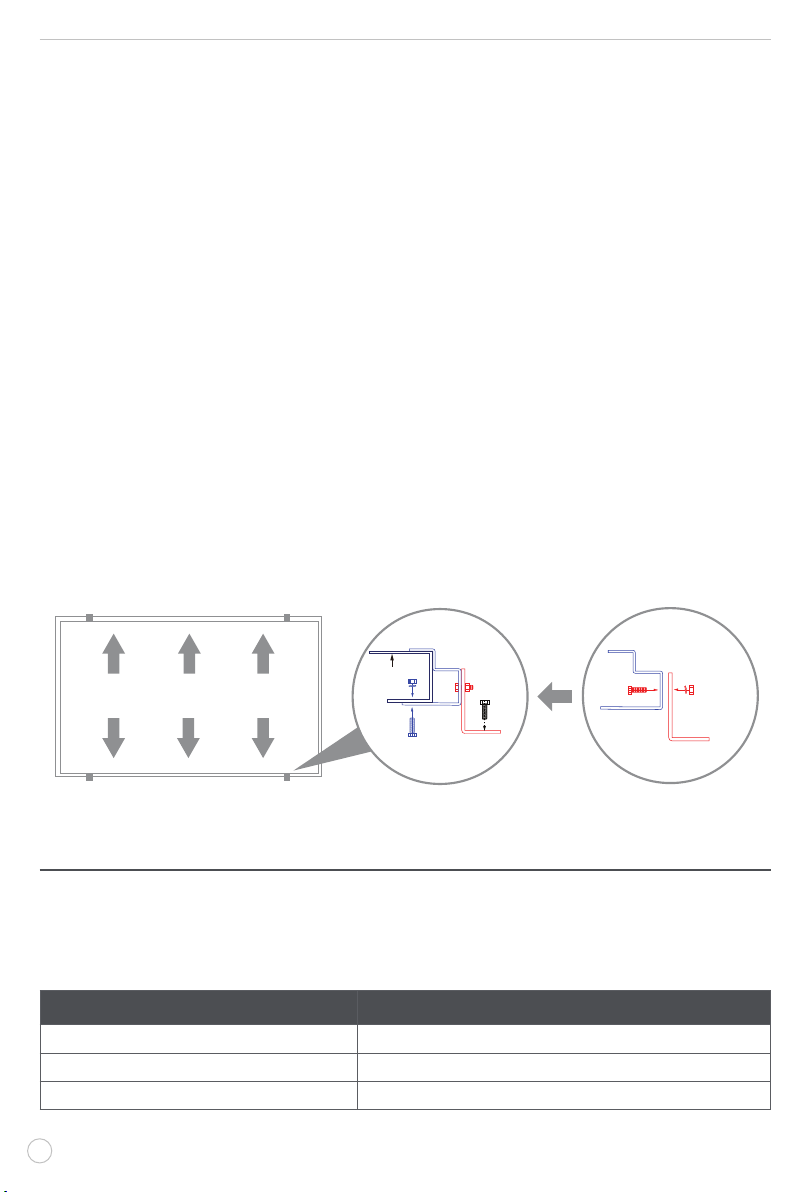
–Drainage holes must not be covered with parts of the mounting system. The
junction box has a breather port which must be mounted facing downward and
cannot be exposed to the rain. The junction box should be on the higher side of
the module when it is mounted in order to orient the breather port correctly.
–Do not lift the module by grasping the module's junction box or electrical leads.
–Do not stand or step on the module.
–Do not drop the module or allow objects to fall on the module.
–Do not place any heavy objects on the module.
–Inappropriate transport and installation may damage the module's glass or frame.

6
Selecting the Mounting Location
–Select a suitable location for the installation of the module.
–The module should be installed to reduce the amount of shading.
–Modules should be mounted as far away from rooftop obstructions (AC units,
plumbing vents, skylights, etc.) as possible.
–If solar panels must be installed near rooftop obstructions, try to orient the
modules with broadside facing the obstruction. This orientation will optimize the
high by-pass diodes in shaded conditions.
–When possible, mount solar panels so that the majority of surfaces can be
oriented south facing if roof is positioned accordingly.
Selecting the Proper Mounting Structure and
Hardware
–Observe all instructions and safety precautions included with the mounting
system to be used with the module.
–Do not drill holes in the glass surface of the module. Doing so will void the
warranty.
–Do not drill additional mounting holes in the module frame. Doing so will void the
warranty.
–Modules must be securely attached to the mounting structure using six mounting
points for normal installation.
–Load calculations are the responsibility of the system designer or installer. The
mounting structure and hardware must be made of durable, corrosion-and UV-
resistant materials.
–Select mounting location such that screw holes on the mounting brackets
attached to the solar panel frame are aligned with the structural framing of the
roof.
Mounting Methods
–The module mounting structure must be made of durable, corrosion-resistant and
UV- resistant materials. A Furrion brand Mounting Kit is recommended, Furrion
model number C-FSFP37MW-A01.
–In regions with heavy snowfall in winter, select the height of the mounting system
so that the lowest edge of the module is not covered by snow for any length
of time. In addition, ensure that the lowest portion of the module is placed high
enough so that it is not shaded by plants or trees or damaged by flying sand.
–Modules must be securely attached to the mounting structure.
–Provide adequate ventilation under the modules in conformity to your local
regulations. A minimum distance of 4" (100mm) between the roof plane and the

7
frame of the module is generally recommended.
–Always observe the instructions and safety precautions included with the module
support frames.
–Before installing modules on a roof, ensure that the roof construction is suitable.
In addition, any roof penetration required to mount the module must be properly
sealed to prevent leaks.
–Observe the linear thermal expansion of the module frames [the recommended
minimum distance between two modules is ⁄" (10mm)].
–Always keep the back-sheet of the panel free from foreign objects or structural
elements, which could come into contact with the panel, especially when the
panel is under mechanical load.
–Ensure panels are not subjected to wind or snow loads exceeding the maximum
permissible loads (176lbs/80kg), and are not subject to excessive forces due to
the thermal expansion of the support structures.
Secure the Solar Panel to the RV Roof
1. Mount the solar panel through the such that at least 4 of the mounting feet have
screws penetrating the metal or wooden framing trusses. For fixed mounting, the
points should be installed with M8*25 bolts and nuts in the frame on the long side
of the panel, as shown below:
SET B
SET A
M8 bolts/nylon
lock nuts x 2 sets
SET B
SET A
M8 bolts/nylon
lock nuts x 1 set
Solar Panel Frame
ELECTRICAL CONNECTION
To power the Solar Photovoltaic System properly, the following Furrion components
are also required except the solar panel. Please contact Furrion authorized dealer to
purchase the product(s) as required and refer to the individual instruction manual that
comes with the product to set up the system.
Furrion Model# Description
C-FSFP37MW-A01 Mounting Bracket
C-FSEB30JWL-BL-004 MC4 to Furrion Connector Adapter
FSCC30PW-BL/FSCC60PW-BL MPPT Solar Charge Controller

8
C-FSCC60PW-A01/C-FSCC60PW-A02 Temperature Sensor
FSEB30JWO-BL Rooftop Solar Electrical Box
FBF12A100E LiFePo4 Battery Pack
+
Disconnect
Fuse\Breaker
Fuse
Rooftop Solar
Electrical Box
FSEB30JWO-BL
+
-
-
Rigid Solar Panel
FSFP37MW-BL
Battery
+ -
Temperature Sensor
C-FSCC60PW-A01
C-FSCC60PW-A02
FBF12A100E
MPPT Solar Charge Controller
FSCC30PW-BL
FSCC60PW-BL
System Connection Diagram
Optional
WARNING: Electrical shock hazard! Do not touch bare conductors or other
potentially energized parts.
–Any hardware used must be compatible with the mounting structure material to
avoid galvanic corrosion.
–It is not recommended to use modules with different configurations (grounding,
wiring) in the same system.
–The current, voltage, and power characteristics of the solar panel(s) will vary
based on environmental criteria including temperature and solar irradiance.
–To prevent cables and connectors from overheating, the cross section of the
cables and the capacity of the connectors must be selected to suit the maximum
system short circuit current (the gauge of system cables is determined by the
system designer or installer.).
SHUTTING DOWN THE SYSTEM
1. Completely cover system modules with an opaque material to prevent electricity
from being generated while disconnecting connectors.
2. Disconnect system from all power sources in accordance with instructions for all
other components used in the system.
The system should now be out of operation and can be dismantled. In doing so,
observe all the safety instructions as applicable to installation.

9
MAINTENANCE
Maintaining Solar Panel
To ensure optimum module performance, the following maintenance measures are
recommended:
–Clean the glass surface of the solar panel when required. Always use clean water
and a soft sponge or cloth for cleaning. A mild, non-abrasive cleaning agent
may be used to remove stubborn dirt. Do not use cold water to clean panel if the
surface is extremity hot as rapid temperature change could lead to cracking.
–Clean solar panel more frequently during drier months, as they may become
covered in dust more quickly. A pressure washer is not recommended.
–Check the electrical, grounding and mechanical connections every six months to
verify that they are clean, secure, undamaged and free of corrosion.
–Remove snow, ice, or other debris when build up occurs.
–Caution: Observe the maintenance instructions for all components used in the
system, such as support frames, PV connectors, charge controller, inverter,
batteries, etc.
Long Term RV Storage
If your RV will be stored in extremely cold climates you may need to remove your
batteries to prevent them from freezing. Please note if your solar panel(s) are covered
by snow they will not produce power and can not be depended upon to keep the
batteries charged. For battery storage in mild climates solar system will provide
more power provided sufficient sunlight and limited load. Make sure that all passive/
phantom loads are removed from the batteries, i.e. DVD players, clock radio, etc. to
make sure the solar panel(s) can keep the batteries charged even with reduced sun
exposure.

10
SPECIFICATIONS
This solar modules are made of monocrystalline solar cells in series with high
efficiency, high transmission rate, low iron tempered glass, anti-aging EVA, high flame
resistant TPT laminate, and anodized aluminum alloy frames. They are designed for
easy installation, extended longevity, and resistance to damage incurred by high wind
or hail.
Specifications
Output cable 14 AWG PV Cable
Connectors Standard MC-4 Connectors
Junction box IP68 Rated
Bypass diode Schottky Barrier Rectifiers Diode
Construction
Front: high transmission rate and low iron tempered glass ⅛" (3.2mm)
Back: TPT
Encapsulation material: EVA
Frame Black Anodized Aluminum
Dimension (W x H x D) 40⅞x 69⅛ x 1⅜" (1038 x 1755 x 35mm)
Weight 40.2lbs (20.5kg)
Cable Length 47¼" / 1200mm
Solar cell 120 pieces monocrystalline silicon solar cell
Max Power (Pmax) 370W
Operating Voltage (Vmp) 34.2V
Operating Current (Imp) 10.82A
Open-Circuit Voltage (Voc) 41.0V
Short-Circuit Current (Isc) 11.42A
Output Tolerance ±5%
Max Series Fuse Rating 20A
Module Efficiency 20.31%
Temperature Coefficient of Voc -0.30%/°C
Temperature Coefficient of Isc +0.05%/°C
Temperature Coefficient of Pmax -0.39%/°C
Operating Temperature -40°F to +185°F (-40°C to +85°C)
NOTE: All technical data at standard test condition (E=1000W/m² TC=25°C AM=1.5)

IM-FEN00035 V1.0
The contents of this manual are proprietary and copyright protected by
Lippert. Lippert prohibits the copying or dissemination of portions of this
manual unless prior written consent for an authorized Lippert
representation has been provided. Any unauthorized use shall void any
applicable warranty. The information contained in this manual is subject
to change without notice and at the sole discretion of Lippert. Revised
editions are available for free download fro lippert.com.
Please recycle all obsolete materials.
For all concerns or questions, please contact Lippert
Ph: 432-LIPPERT (432-547-7378) | Web: lippert.com | E-mail:
CCD-0006081 | REV DATE: 10.20.22
Table of contents
Other Lippert Solar Panel manuals
Popular Solar Panel manuals by other brands

Vaillant
Vaillant VPV P 290/2 M SWF Operating, installation and maintenance instructions

PHOTON SOLAR
PHOTON SOLAR PH-185M-72 Safety & installation instructions

Solaria
Solaria 230W Safety, installation, and operation manual

Wasserstein
Wasserstein Solar Panel Compatible with Logitech Circle... user manual

Kyocera
Kyocera OBSTRUCTION LIGHTING datasheet

Tindo Solar
Tindo Solar Karra Series installation manual