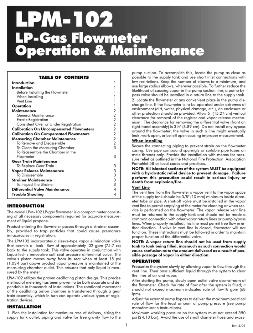
Liqua-Tech LPM-101 Manual

LPM-101
LP-Gas Flowmeter
Operation & Maintenance
INTRODUCTION
The Model LPM-101 LP-Gas flowmeter is a compact meter consist-
ing of all necessary components required for accurate measurement
of liquid propane.
LPM-101 utilizes the proven oscillating piston design. This precise
method of metering has been proven to be both accurate and de-
pendable in thousands of installations. The rotational movement of
the oscillating piston chamber is transferred through a gear train as-
sembly, which in turn can operate various types of registration de-
vices.
INSTALLATION
1. Plan the installation for maximum rate of delivery, sizing the sup-
ply tank outlet, piping and valve for free gravity flow to the pump
suction. To accomplish this, locate the pump as close as possible to
the supply tank and use short inlet connections with few restrictions.
Keep the number of elbows to a minimum, and use large radius el-
bows, wherever possible. To further reduce the likelihood of causing
vapor in the pump suction line, a pump bypass valve should be in-
stalled in a return line to the supply tank.
2. Locate the flowmeter at any convenient place in the pump dis-
charge line. If the flowmeter is to be operated under extremes of en-
vironment (dirt, water, physical damage, etc.), an enclosure or other
protection should be provided. Allow vertical clearance for removal
of the register . Do not install any bypass around the flowmeter; the
valve in such a line might eventually leak, work open, or be left open
causing improper measurement.
When Installing
Secure the connecting piping to prevent strain on the flowmeter cas-
ing. Use pipe compound sparingly or suitable pipe tapes on male
threads only. Provide the installation with means for pressure relief
as outlined in the National Fire Protection Association Pamphlet 58
or local codes and practices.
NOTE: All isolated sections of the system MUST be equipped
with a hydrostatic relief device to prevent damage. Failure to
perform this precaution could result in serious injury or death
from explosion/fire.
OPERATION
Pressurize the system slowly by allowing vapor to flow through the
vent line. Then pass sufficient liquid through the system to clear the
lines of air and vapor.
After starting the pump, slowly open outlet valve downstream of the
flowmeter. Check the rate of flow after the system is filled; it should
not exceed maximum indicated rate of flow18 gpm (68 lpm).
Adjust the external pump bypass to deliver the maximum practical
rate of flow for the least amount of pump pressure (see pump manu-
facturer’s instructions).
Maximum working pressure on the system must not exceed 350 psi
(24.13 bar). Avoid the use of small diameter hose and excessive
pressures to achieve the desired flow rates; these may result in leak-
age and undue wear on the pump.
Although all flowmeters are carefully calibrated and tested after as-
sembly and no changes should be necessary; field calibration is rec-
ommended after installation is complete.
MAINTENANCE
General Maintenance
For sustained accuracy of flowmeters, little maintenance is required
other than to see that the proper conditions of operation are pre-
served. Once the flowmeter has been installed correctly, these con-
ditions consist merely in guarding against foreign matter, such as
vapor, sediment, or water entering the measuring chamber. How-
ever, should any malfunction develop, do not dismantle the
flowmeter until the cause of the trouble has first been determined.
(Refer to TROUBLESHOOTING.)
Sediment - The liquid passing through the measuring chamber
must be free of grit and other forms of sediment to prevent unneces-
sary friction and to eliminate scoring of the piston and chamber
walls. Evidence of trouble from this source will be found in un-
der-registration of the flowmeter.
Vapor - Being an instrument that measures by volume, a flowmeter
will record the passage of vapor as well as the liquid being mea-
sured. Over-registration will result.
Water - Incidental water will cause no damage to the flowmeter.
Trouble from this source may be expected when water is allowed to
remain in the flowmeter.
Erratic Registration
Erratic registration is usually caused by vaporization of the product
or by dirt or pipe scale in the measuring chamber (under-registra-
tion). Clean the flowmeter if necessary, as directed in
MAINTENANCE.
Consistent Over- or Under- Registration
When the flowmeter consistently registers either more or less than is
delivered and no other cause in system function can be determined,
calibration of the metering system is recommended.
TABLE OF CONTENTS
Introduction 1
Installation 1
Before Installing the Flowmeter 1
When Installing 1
Operation 1
Maintenance 1
General Maintenance 1
Erratic Registration 1
Consistent Over or Under Registration 1
Calibration 2
Measuring Chamber Maintenance 2
To Remove and Disassemble 2
To Clean the Measuring Chamber 2
To Reassemble the Chamber in the
Flowmeter 2
Gear Train Maintenance
To Replace Gear Train 2
Change Gear Chart 3
Troubleshooting 3
1

CALIBRATION
Test the flowmeter using a volumetric prover large enough to permit
the flowmeter to operate for at least one minute at normal flow rate.
Slip tube and rotary gauge reading are not sufficiently accurate for
proving flowmeters. A detailed description of an LP-Gas test proce-
dure may be found in the National Bureau of Standards Handbook
99, “Testing Liquefied Petroleum Gas Liquid-Measuring Devices”.
If a gravimetric test method is used, the conversion to gallons must
be on the basis of: (1) specific gravity determined at the time of the
test (not an assumed value), and (2) the temperature of the product
as it is passed through the flowmeter. The volumetric test method,
however, is considered to yield more accurate results and is pre-
ferred. After performing the test procedure:
1. Determine the percentage of over-or under-delivery for each test
conducted.
2. Remove the register screws and take off the register.
3. Note the numbers stamped on the “R” change gear (on register
spindle) and on the “S” (or flowmeter spindle). Locate the gear tooth
combination on the Change Gear Chart.
4. Add the step-wise increments of change in registration until the
desired amount is reached. If the flowmeter is under-registering (de-
livering too much), select a new pair of gears farther down the chart.
If the flowmeter is over-registering (delivering too little), select a new
pair of gears farther up the chart.
5. Remove the old change gears and replace them with the new
pair. Always place the change gear with the smaller number of teeth
on the “R” register shaft and the gear with the greater number of
teeth on the “S” flowmeter shaft. To remove change gears, close the
split end of the spindle slightly with a pair of pliers to permit removal
of the change gear. After slipping on the new gear, spread the ends
of the spindle slightly.
6. Reinstall the register, run several gallons (liters) through the
flowmeter, and retest.
MEASURING CHAMBER MAINTENANCE
CAUTION: Be sure meter is completely relieved of pressure
before performing any internal maintenance. Pressure must
be 0 psig (0 bar). Failure to properly depressurize and evacu-
ate the system could result in serious injury or death from ex-
plosion/fire.
Perform the following outdoors, away from buildings and
sources of ignition. Replacement gaskets should be on hand.
To Remove and Disassemble
This operation is not difficult and may be performed by any compe-
tent mechanic. No special tools are required if these few simple but
important directions are followed. Do not open the flowmeter until
you have checked over all other possible causes of erratic registra-
tion. (Refer to TROUBLE SHOOTING.)
1. Prepare a clean surface on which to place the parts as they are re-
moved. (The parts are machined to close tolerances and should be
handled with care.) Also check that a replacement gasket is on hand
before opening the flowmeter, it may need to be replaced.
2. Remove the main case cover taking care not to damage the gas-
ket, if it is to be reused.
3. Lift the measuring chamber from the flowmeter casing.
4. Remove the top plate by inserting a screwdriver in one of the slots
provided, and prying it off. Be careful not to scratch or nick any part
of the chamber.
5. Lift out the piston by its spindle. If care is taken to draw it straight,
it should come out easily. Do not force it.
6. Remove the control roller from the lower cylinder head. If the dia-
phragm or seal pin requires replacement, they may be removed by
pulling upward, using pliers if necessary.
To Clean the Measuring Chamber
The parts may be most easily cleaned of scale, embedded chips,
heavy corrosion and other foreign matter, using gasoline and a
stiff-bristle (not wire) brush. Do not use abrasives, such as emery
cloth or sandpaper. When the piston is badly corroded, replace the
whole chamber.
The sliding surfaces between the chamber and piston take on a bur-
nished finish and wear little if any. The parts of the measuring cham-
ber which may show wear after long periods of service are the
diaphragm and the control roller. These parts will not require re-
placement until the accuracy of the flowmeter fails at low rates of
flow. To change these parts, merely substitute new parts for the old,
when the flowmeter is disassembled for cleaning.
To Reassemble the Chamber in the Flowmeter
Before assembling the flowmeter, make sure all parts are clean. If
possible, flush out the flowmeter body. Assemble the parts carefully;
they should slide together easily without hammering or forcing. It is
essential that all contact surfaces between the upper and lower cylin-
der heads and the cylinder, or between the measuring chamber and
its seat in the casing, be free from nicks.
1. Assemble the diaphragm and seal pin in the chamber, if replace-
ment of these parts was necessary.
2. Place the control roller on its pin, and see that it will rotate freely.
3. Reinstall the piston, and oscillate it carefully by hand; it should
move easily without binding. If it sticks, do not force it, but remove it
and locate the cause. Do not file down the roller as this will destroy
the accuracy of the flowmeter.
4. Reinstall the top plate, and again oscillate the piston to make sure
that it is free.
5. Before installing the measuring chamber in the casing, make sure
that the seat is clean and free of nicks. Install the chamber, making
sure that the dowel pin in the main casing enters the slot in the bot-
tom housing properly and allows the chamber to rest squarely on
the seat. The top of the chamber should be flush with the gasket
seal.
GEAR TRAIN MAINTENANCE
CAUTION: Be sure meter is completely relieved of pressure
before performing any internal maintenance. Pressure must
be 0 psig (0 bar). Failure to properly depressurize and evacu-
ate the system could result in serious injury or death from ex-
plosion/fire.
Perform the following outdoors, away from buildings and
sources of ignition. Replacement gaskets and seals should be
on hand.
To Replace Gear Train Shaft Seal
1. Remove the register.
2. Remove the stuffing box nut.
3. Remove shaft seal. Inspect top of spindle to be sure it is free of
nicks or burrs which might damage the new shaft seal when it is
placed on spindle.
4. Replace shaft seal. Be sure expander and spring are in position
before inserting new seal.
5. Assemble nut and tighten down all the way.
To Replace Gear Train
1. Remove the register.
2. Remove the flowmeter main case cover, with gear train assembly
attached. Be careful to keep dirt out of flowmeter, and avoid dam-
age to the cover gasket (a replacement gasket may be necessary).
3. Remove the stuffing box nut.
4. Take off the clamp nut and remove the gear train assembly from
the underside of the flowmeter top casing.
5. Install replacement gear train, making sure that the replacement
has the same gear reduction, new seal, and new gear train is orien-
tated with anti-rotation pin. Both clamp nut and stuffing box nut
should be torqued to 200 inch lbs.
7. Before installing the top casing, inspect the gasket and replace if
necessary. Next, position the driving arm of the gear train so that it
will not rest on the piston spindle. Then reassemble the main case
cover on the main casing and secure it with the four cap screws.
2

Pressure buildup in tank being filled. Condition becomes worse as delivery nears completion unless vapor space type filling is
used.
High loss of head. (This is caused by too many valves and elbows and the length. diameter and condition of the delivery
hose.)
Pump vapor bound due to improper installation of bypass relief valve or a restriction in suction line. (Refer to
“INSTALLATION”)
Pump too small or inefficient. (The pump must have sufficient capacity and pressure to pump against higher heads than are
normally found in gasoline or fuel oil installations. This is especially true when the delivery nears completion.)
Change Gear Combination % Change in LPG Passed
“R” Shaft Gear “S” Shaft Gear Gallons
(43.5)
Liters
(11.6/116.875)
Decreases Amount Registered (Indicated)
34 35 2.32% 3.95%
33 34 2.23% 3.86%
32 33 2.14% 3.77%
31 32 2.04% 3.67%
30 31 1.93% 3.56%
29 30 1.81% 3.44%
28 29 1.69% 3.32%
27 28 1.56% 3.19%
26 27 1.42% 3.05%
25 26 1.26% 2.89%
24 25 1.10% 2.73%
23 24 0.92% 2.55%
22 23 0.72% 2.35%
21 22 0.50% 2.13%
20 21 0.26% 1.89%
19 20 0.00% 1.63%
18 19 -0.29% 1.34%
Change Gear Combination % Change in LPG Passed
“R” Shaft Gear “S” Shaft Gear Gallons
(43.5)
Liters
(11.6/116.875)
34 36 -0.62% 1.01%
33 35 -0.80% 0.83%
32 34 -0.99% 0.64%
31 33 -1.19% 0.44%
30 32 -1.40% 0.23%
29 31 -1.63% 0.00%
28 30 -1.88% -0.25%
27 29 -2.14% -0.51%
26 28 -2.43% -0.80%
25 27 -2.74% -1.11%
24 26 -3.07% -1.44%
23 25 -3.43% -1.80%
22 24 -3.83% -2.20%
21 23 -4.26% -2.63%
20 22 -4.74% -3.11%
19 21 -5.26% -3.63%
Increases Amount Registered (Indicated)
CHANGE GEAR CHART
Gear calibration will be determined by adjusting the high
flow result (averaged) to the closest corresponding set of
change gears. If possible, adjustment should be made by
bracketing the high and low flow tests.
Example
Meter is under registering (pumping more LPG than is registered). The amount
indicated on the register needs to be increased. Starting gears are R=33, S=35.
By changing these gears to R=32, S=34, an increase in registration of +.19% is
achieved (Difference between -.80% and -.99% is .19%)
TROUBLESHOOTING
Complaint Possible Cause
Register not working when
liquid is flowing
Bypass around flowmeter not shut off
Ice inside register
Loose register or worn gear train
Register in need of repair
Sheared key on change gear caused by ice in register or mechanically tight mechanism
Change gear has ridden up its shaft and not engaging the other change gear
Leakage at the stuffing box Worn shaft seal or spindle
Chronic leakage at the main
case gaskets
Excessive line or shock pressure
Defective gasket or loose bolts
Unsatisfactory flow rate or
complete stoppage of flow
Pump bypass stuck open or spring weak
Piston in flowmeter stuck. Clean measuring chamber.
Open valve in piping allowing liquid to circulate around pump
Worn pump
Pump/motor not rotating in proper direction
Under-registration - erratic
Dirt in the measuring chamber
Badly worn control roller or diaphragm
Main casing distorted or damaged
Consistent over- or
under-registration Flowmeter in need of calibration
Liqua-Tech Corporation 3501 N. State Street, Ukiah, CA 95482 800/659-3556, FAX 707/462-3576 www.liqua-tech.com [email protected]
3
Other Liqua-Tech Measuring Instrument manuals
Popular Measuring Instrument manuals by other brands
Fukuda
Fukuda VaSera VS-2000 Series Operation manual
Gecko
Gecko Compact Product user manual
Spirax Sarco
Spirax Sarco RIM10 Series Installation and maintenance instructions

Ahlborn
Ahlborn ALMEMO 2290-2/3 operating instructions
ACS contsys
ACS contsys Flowcont UN operating instructions
LDL TECHNOLOGY
LDL TECHNOLOGY TCU Mounting procedure
