meitav-tec M4000MD User manual
M4000MD
Digital HVAC Analyzer
Owner’s Manual

TABLE of CONTENTS
1. INTRODUCTION 3
2. FEATURES 4
3. WARNINGS & PRECAUTIONS 5
4. INSTRUMENT DESCRIPTION 6
5. OPERATING INSTRUCTIONS
5.1 UNITS OF MEASURE 7
5.2 TURN THE UNIT ON OR OFF 8
5.3 MEASURING TEMPERATURE AND DEW POINT 9
5.4 MEASURING HUMIDITY LEVEL 10
5.5 MEASURING AIR VELOCITY 11
5.6 MEASURING AIR VOLUME 10-12
5.7 MEASURING CAPACITY 13-16
6. MAINTENANCE 17
6.1 LOW BATTERY INDICATION 17
6.2 BATTERY REPLACEMENT 17
7. SPECIFICATIONS 18

1. INTRODUCTION
Congratulations! You now own one of the finest HVAC tools available today.
The unique M4000MD provides you with all the necessary information to
measure HVAC performance – including Temperature, Humidity, Dew Point,
Velocity, Volume and Capacity.
The M4000MD can be used for anything from simple Temperature readings to
complex multi-outlet computations of BTU's, from Humidity measurement to
system balancing or total outlet output. An advanced measurement instrument
designed for in field use, the M4000MD is lightweight, completely portable and
ergonomically designed. Three simple keypad buttons control the unit, providing
quick and easy operation. An advanced microprocessor does all the
computations needed – and the results are displayed on a large LCD screen.
For the best results with your new M4000MD, please read this manual carefully.
It describes operation, care and additional information that will allow you to get
the greatest benefit from your new instrument.

2. FEATURES
Temperature in °C and °F
Humidity in % Relative Humidity
Air Velocity in m/sec
Air Volume in m
3
/sec and CFM
Capacity in kW and Btu/h
Dew Point in °C and °F
Allows the measuring of round grills
Memory allows Cumulative Volume and BTU measurements
Keypad Controls
Portable and Lightweight
Durable sensing mechanisms
1.8m (Six foot) coil cord
Tough ABS housing
75 mm x 45 mm (3” x 1.75”) Large Liquid Crystal Display
Carrying Case Included

3. WARNINGS & PRECAUTIONS
When the instrument is first introduced into a new environment, i.e. from a
service vehicle into a building, allow 10 minutes for the instrument’s
humidity sensor to stabilize.
Remember to allow unit readings to stabilize in order to avoid false
readings.
Do not place Sensor Cover in direct contact with any surface, especially
extremely hot or moist ones.
Do not expose Sensor to temperatures outside its range.
Do not expose Fan to velocities above its range.
Avoid contact with solvents and liquids.
Avoid extreme mechanical shook or vibrations.
Always take care to keep the coil cord free of rotating objects such as fan
blades or cages.
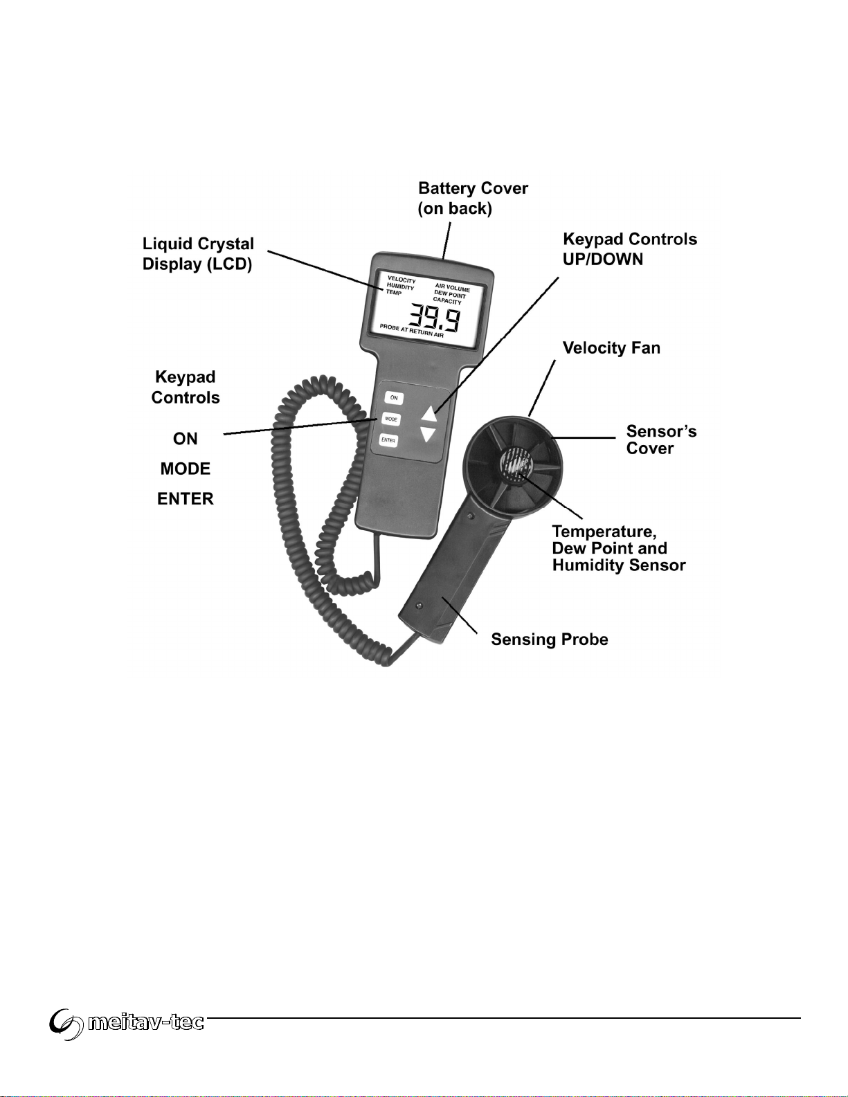
4. INSTRUMENT DESCRIPTION

5. OPERATING INSTRUCTIONS
5.1. Units of Measure
PARAMETER METRIC English - Press [▼]
Temperature °C °F
Humidity %RH
Velocity meters/sec
Width / Length Centimeter
Air Volume M
3
/sec CFM
Capacity kW BTU/H
Dew Point °C °F
5.2. Turn the unit ON or OFF
5.2.1. Press the [ON] button - the unit will beep and the LCD lights.
5.2.2. Press [ON] button again to switch the unit off.
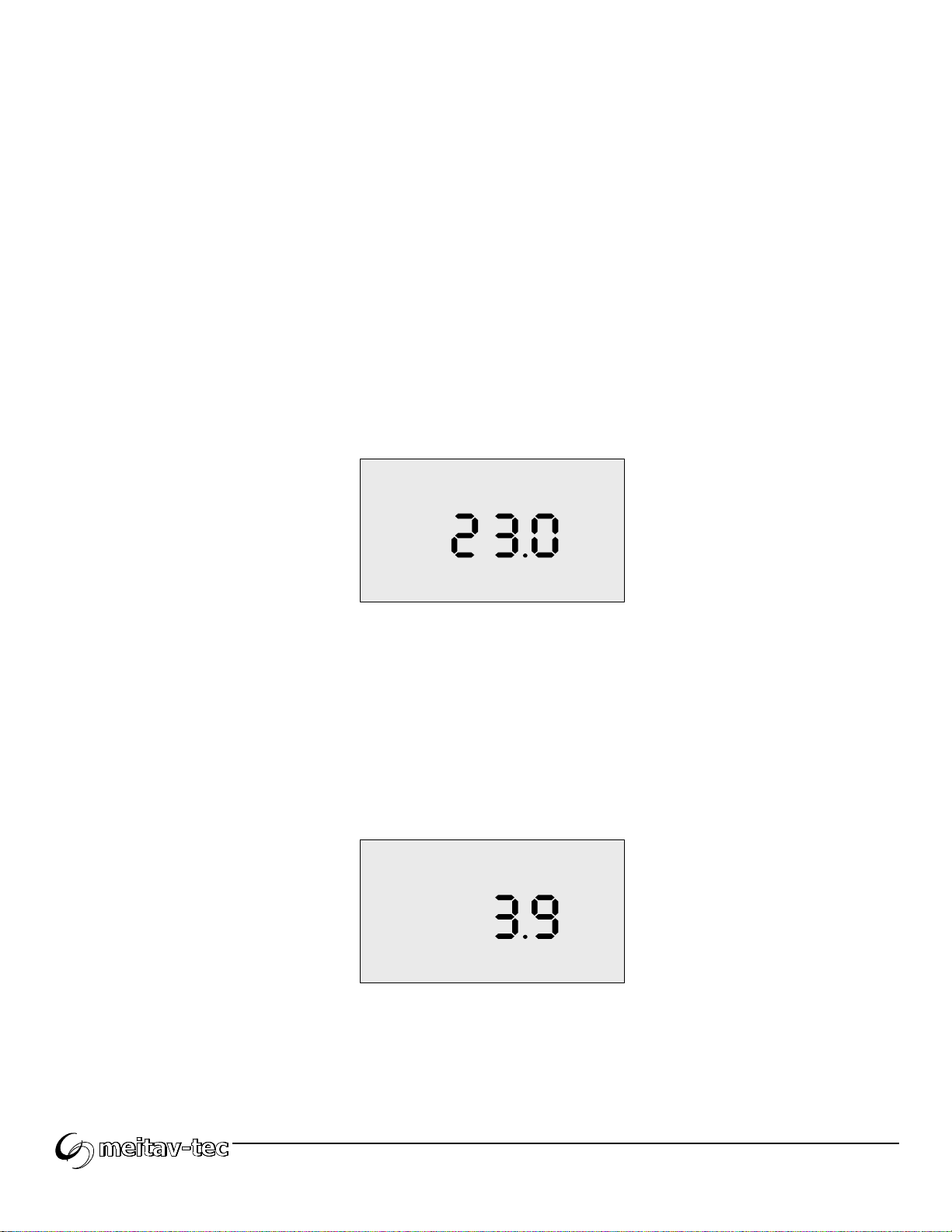
5.3. Measuring Temperature and Dew Point
5.3.1. The M4000MD will switch on in the TEMP mode. If already in another
mode, press the [MODE] button until TEMP is displayed on LCD.
TEMP
oC
5.3.2. Place the probe in front of the outlet (or the area to be measured) so that
the SENSOR’S COVER IS FACING THE OUTLET.
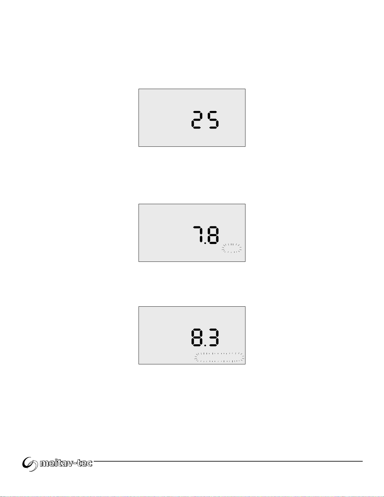
5.3.3. The temperature in °C is displayed. Press [▼] for °F.
5.3.4. To display Dew Point - Press [▲]. Dew Point is displayed in °C.
Press [▼] for °F
DEW POINT
oC

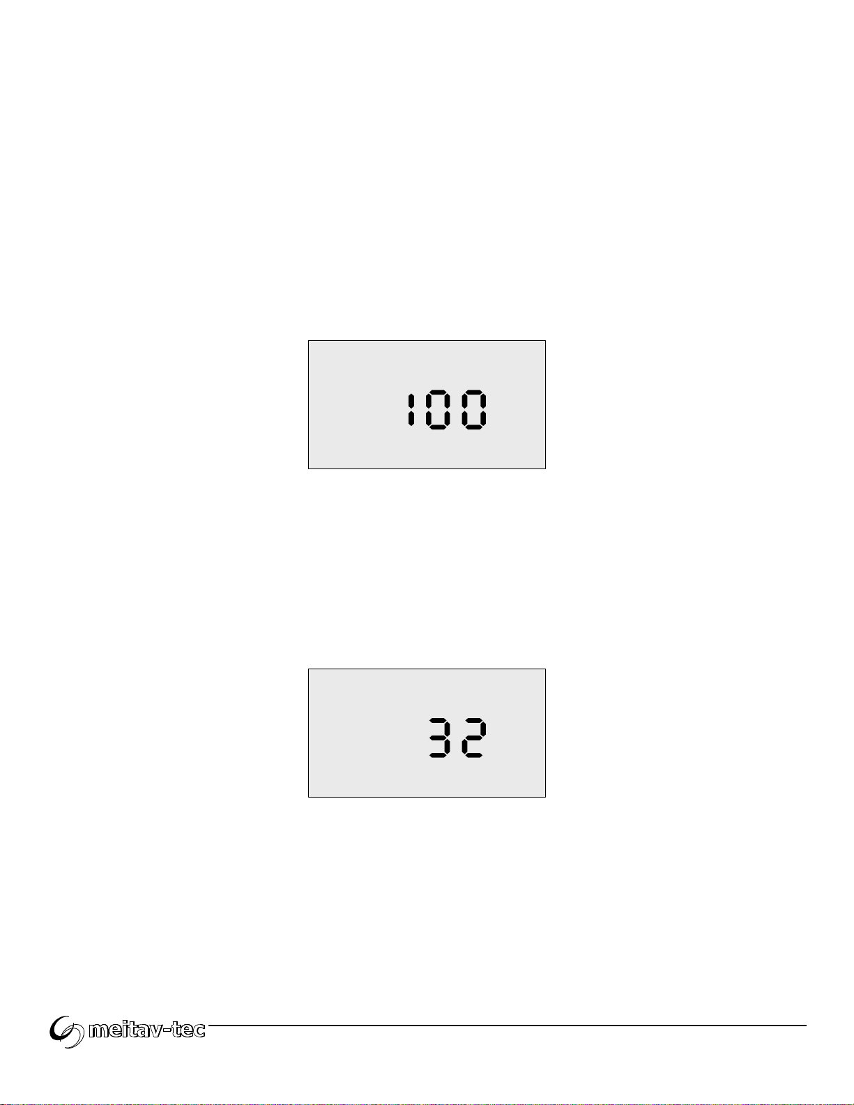
5.4. Measuring Humidity Level
5.4.1. Press the [MODE] button – “HUMIDITY%” will be displayed on LCD.
5.4.2. Place the probe in front of the outlet (or area to be measured) so that the
sensor’s cover is facing the outlet.
5.4.3. Relative Humidity level in %RH is displayed.
HUMIDITY%
5.5. Measuring Air Velocity
5.5.1. Press the [MODE] button – “VELOCITY” will be displayed on LCD.
5.5.2. Place the probe in front of the outlet (or area to be measured) so that the
sensor’s cover is facing the outlet.
5.5.3. Air velocity in meters per second (m/s) is displayed.
VELOCITY
m/s
5.6. Measuring Air Volume
5.6.1. Press the [MODE] button – “AIR VOLUME” and “ENTER WIDTH”
(flashing) will be displayed on LCD.
The M4000MD is requesting the A/C outlet’s width.
5.6.2. Using the [▲] and [▼] buttons, enter the appropriate measurement in
centimeters.
AIR VOLUME
cm
ENTER WIDTH
5.6.3. Press [ENTER] to store the width in memory. – "AIR VOLUME" and
“ENTER LENGTH” (flashing) will be displayed on LCD.
The M4000MD is requesting the A/C outlet’s length.
5.6.4. Using the [▲] and [▼] buttons, enter the appropriate measurement in
centimeters. DO NOT PRESS ENTER UNTIL STEP 5.5.7
AIR VOLUME
cm
ENTER
LENGTH
5.6.5. To measure round grills – after step 5.5.1 press and hold the [ENTER]
button for more than 2 seconds, until "ENTER" and "DIAMETER" are
flashing on LCD.
The M4000MD is requesting the A/C outlet’s diameter.
5.6.6. Using the [▲] and [▼] buttons, enter the appropriate measurement in
centimeters. DO NOT PRESS ENTER UNTIL STEP 5.5.7
cm
ENTER
DIAMETER
5.6.7. Place the probe in front of the unit’s outlet so that the sensor’s cover is
facing the outlet. Press [ENTER]. The M4000MD will flash" WAIT" for
about 20 seconds.
VELOCITY
m/s
AIR VOLUME
WAIT
START AVERAGE
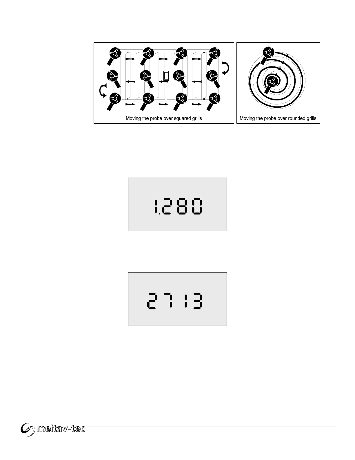
Keep the probe in front of the outlet’s grill and when "START AVERAGE"
begins to flash, move the probe back and forth across the unit’s outlet.
VELOCITY
m/s
AIR VOLUME
WAIT
START AVERAGE
Make sure to cover the complete area of the grill, moving the probe at a
rate of speed to cover the entire grill in less than 10 seconds. Go back
and repeat moving the probe across the outlet for one minute.
At the end of one minute the M4000MD will beep, signaling that the
measurement time has ended and the LCD will display the
measured Air Volume in M
3
/sec.
AIR VOLUME
m3/s
To display Air Volume in CFM (cubic feet per minute) press and
hold the [▼] button.
cfm
AIR VOLUME
Note: Aim at getting readings from all available openings.
5.6.8. To repeat this measurement or IF YOU WISH TO MEASURE
ADDITIONAL OPENINGS, press [ENTER] and repeat steps 5.5.2 - 5.5.7.
Measure each opening as previously described in order to obtain an
overall average reading. At the completion of each test, the sum of ALL
measurements can be displayed by pressing the [▲] button.

5.7. Measuring Capacity
IMPORTANT NOTE: Before you begin to measure capacity, press the
[MODE] button until you reach the "HUMIDITY" mode. Place the probe in
front of the inlet grill, so that the sensor’s cover is facing AWAY FROM
THE INLET GRILL and wait until the humidity measurement stabilizes (this
also allows the “TEMP” measurement to stabilize). DO NOT place the
probe at the output grill because it will take a long time (10 minutes) to
return to normal room humidity and temperature conditions!
5.7.1. Press [MODE] button – until "CAPACITY" appears on LCD.
CAPACITY
kW
Note: When measuring return air it is recommended that the FAN
SPEED IS SET ON HIGH and the probe is placed at the center of the
inlet grill. (No movement is necessary during this measurement).
5.7.2. Align the probe in front, at the center of unit’s inlet, so that the sensor’s
cover is facing AWAY FROM THE INLET grill and press ENTER. The
LCD will display HUMIDITY %, CAPACITY, Probe at RETURN AIR and
"WAIT" will be flashing.
CAPACITY
HUMIDITY%
WAITP obe at RETURN AIR
The M4000MD will start measuring the unit’s inlet air parameters
while displaying a flashing "WAIT". After measuring for one minute,
the unit will beep and the "WAIT" will stop flashing, signaling that
the measurement has ended, and a flashing “ENTER WIDTH” will
be displayed on LCD.
CAPACITY ENTER WIDTH
P obe at
OUTPUT AIR
cm
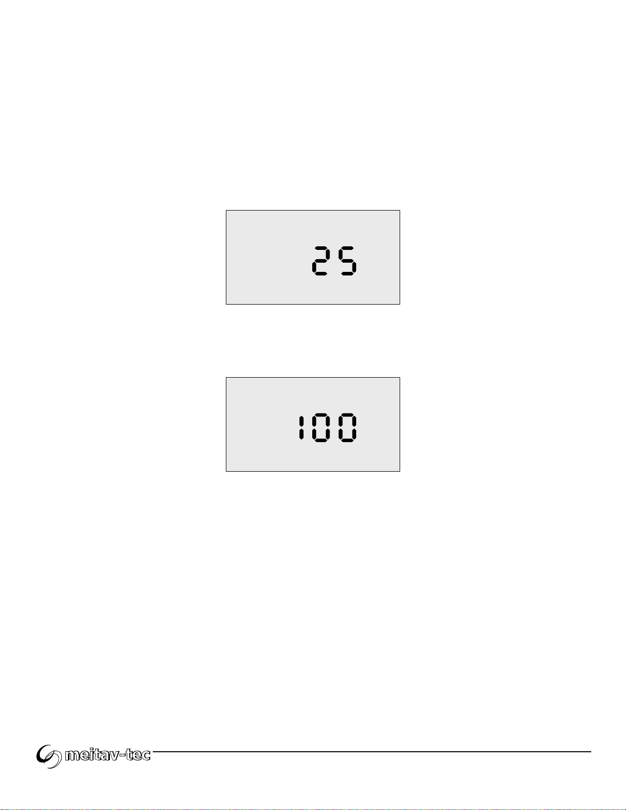
5.7.3. Using the [▲] and [▼] buttons enter the outlet’s width in cm and press
[ENTER]. A Flashing “ENTER LENGTH” will be displayed on LCD.
CAPACITY ENTER
LENGTH
P obe at
OUTPUT AIR
cm
Using the [▲] and [▼] buttons enter the outlet’s length in cm.
DO NOT PRESS [ENTER] UNTIL STEP 5.6.5

5.7.4. To measure round grills - At step 5.6.3, press [ENTER] button for more
than 2 sec until a flashing DIAMETER is displayed on LCD.
CAPACITY ENTER
DIAMETER
P obe at
OUTPUT AIR
cm
Using [▲] and [▼] buttons enter the outlet’s diameter in cm. and then
follow next steps.
5.7.5. Place the probe in front of the outlet so that the sensor’s cover is facing
the outlet and than press [ENTER],the following display will show:
CAPACITY
VELOCITY
WAIT
START AVERAGEP obe at
OUTPUT AIR
"WAIT" will flash. No need to move probe at this time, the M4000MD is
waiting until the sensors stabilize with the new TEMPERATURE and
HUMIDITY readings (about 90 seconds) then “START AVERAGE" will
flash Measure for one minute making sure to move the probe over the
complete area of the grill (Refer to Step 5.5.7). Aim at getting average
readings from all available openings.

At the end of one minute the unit will beep and the LCD screen will
display the results in kW.
CAPACITY
kW
To repeat this measurement, the return air and grill size are already in
memory, simply press [ENTER] and repeat sections 5.6.3 -5.6.5 above.
5.7.6. When there are several outlet openings but the same return air,
press [ENTER] and repeat steps 5.6.3 - 5.6.5 for each one (make sure
you enter the correct width and length for each opening).
In Step 5.6.5 "WAIT" will flash for 20 seconds. Each time a measurement
ends the LCD will display the kW for that specific outlet. At the
completion of each test, the sum of ALL measurements can be displayed
by pressing the [▲] button.
Note: If you wish to go through the complete process of measuring capacity
again, which includes the return air measurement, you should wait 10
minutes to allow the humidity sensor to return to ambient conditions.

6. MAINTENANCE
Your M4000MD requires no maintenance apart from battery replacement.
From time to time wipe the unit clean with a damp cloth. Do not use solvents
or abrasives. Occasionally inspect the coil cord for nicks and/or cuts and
return for replacement if any are found.
6.1. Low Battery Indication
The battery requires replacement when the LCD characters begin to
flash on and off.
6.2. Battery Replacement
To replace the battery, slide the battery compartment cover, located on
the back of the top portion of the unit, upward to access the battery.
Remove and replace with a new and/or a tested 9V alkaline battery.
Replace cover before operation.

7. SPECIFICATIONS
Ranges: Temperature -5°C to 65°C (23°F to 149°F)
Humidity 10-95% RH
Velocity 0.5 to 15 m/sec. (1.8 to 49 fps)
Accuracy: Temperature ± 2°C
Humidity ± 3% RH
Velocity ± 3%
Dew Point ± 3%
Response Time: Temperature < 5 sec.
Humidity < 10 sec.
Velocity Instantaneous
Dew Point < 10 sec.
Operating Temp.: 0°C to 50°C (32°F to 122°F)
Power Supply: One 9V alkaline battery
Battery Life: Approx. 8 hours continuous
Weight: 430g (15 ounces)
Dimensions: Controls 20.3 x 8.9 x 5 cm (8” x 3.5” x 2”)
Probe 17.1 x 7.6 x 5 cm (6.75” x 3” x 2”)
Display 5 digits 75 x 45 mm (3” x 1.75”) LCD
Coil Cord Length 1.8m (72”)

Notes
………………………………………………………………………………………………
………………………………………………………………………………………………
………………………………………………………………………………………………
………………………………………………………………………………………………
………………………………………………………………………………………………
………………………………………………………………………………………………
………………………………………………………………………………………………
………………………………………………………………………………………………
………………………………………………………………………………………………
………………………………………………………………………………………………
………………………………………………………………………………………………
………………………………………………………………………………………………
………………………………………………………………………………………………
………………………………………………………………………………………………
………………………………………………………………………………………………
………………………………………………………………………………………………
………………………………………………………………………………………………
………………………………………………………………………………………………
………………………………………………………………………………………………
………………………………………………………………………………………………
………………………………………………………………………………………………
………………………………………………………………………………………………
………………………………………………………………………………………………
………………………………………………………………………………………………
………………………………………………………………………………………………
………………………………………………………………………………………………
………………………………………………………………………………………………
………………………………………………………………………………………………

www.meitavtec.com | support@meitavtec.com | M4000MD Digital HVAC Analyzer – Owner’s Manual | Pg. 20
M4000MD
File: M4000MD Owner's Manual - Rev.1.doc
Table of contents


