LiquaGen 6 stage User manual

LIQUAGEN 5 STAGE RO INSTRUCTION MANUAL
INSTALLATION MANUAL
6 STAGE RO/DI
PRODUCT PART NUMBER: 2-OS-75
EMAIL:
Phone Support : (951) 400-3365
CONTACT:
1379 Pico St Suite 104, Corona, CA 92881, USA
ADDRESS:
TM

www.liquagen.com
Welcome to the LiquaGen family and thank you for
purchasing our RO/DI unit. You're one step closer to ultra-
pure water and the peace of mind that comes from knowing
the finest American water filtration technology is working for
you. We strive to offer you great value and lifelong service. If
you are satisfied with your purchase please take a moment
to leave a positive review on the product. At LiquaGen we
are always trying to improve and the best feedback we can
get is from our customers. If you have any ideas or
suggestions we'd love to hear from you!
18
FINDING THE RIGHT REPLACEMENT
FILTERS
When replacing your filter, you have the option between two different
kits. The DIY kit will require you to empty your current DI canisters to fill
them with new resin. Your other option is the pre-filled cartridge with DI
resin, eliminating the need to transfer new media.
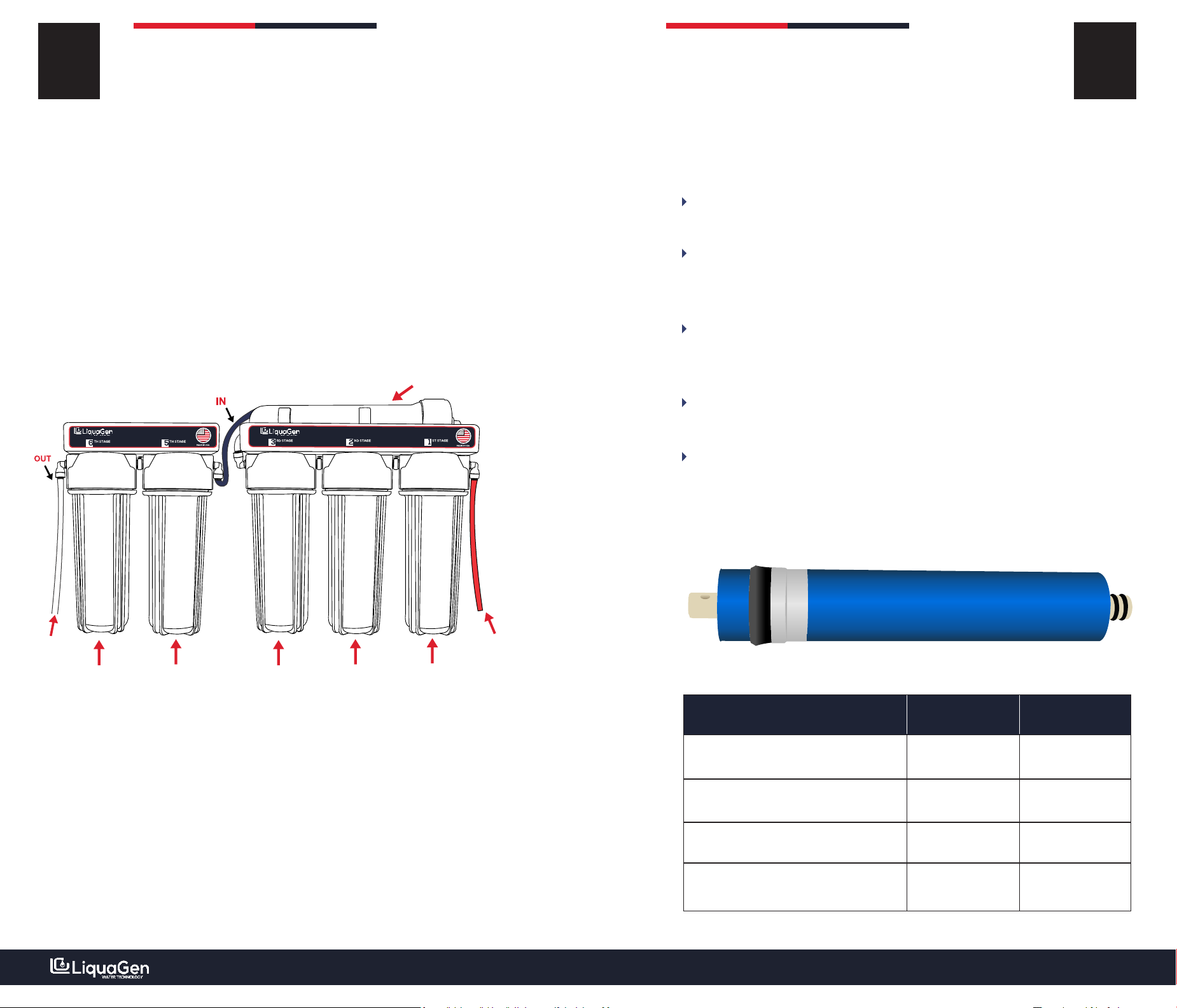
Reverse Osmosis Membrane Size Chart:
PRE-FILTER KIT + DI MEDIA BAG OR PRE-FILLED CARTRIDGE
Match the GPD to your membrane size. Each membrane size is written on
the bracket of the Reverse Osmosis System.
LiquaGen Website Part Number: 2-OS-75
MEMBRANE SIZE PART NUMBER
50 Gallons Per Day
100 Gallons Per Day
150 Gallons Per Day
75 Gallons Per Day ROM - 75
ROM - 150
ROM - 100
ROM - 50
Should you have any questions or concerns please feel free to
contact us on (951) 400-3365.
All replacement filters can be found on www.LiquaGen.com - Search for
the part number on the website and all the needed filters will show up.
NOTE:
www.liquagen.com
17 REPLACEMENT
FILTERS
WHEN DO I KNOW TO REPLACE MY FILTERS?
DI Media
When installing a pressure gauge you can see the pressure on the meter
drop for your pre-filters. When the pressure drops it is a good indicator that
the filters need to changed out. Another way to tell is by looking at your 1st
stage (Sediment) filter, when the color turns dark brown the pre-filters
need to be changed.
2. Increase in TDS - Reverse Osmosis Membrane & DI Media
Reverse Osmosis Membrane
1. Pre-Filter Replacement (S/UDF/C)
Pressure Gauges can be found on liquagen.com - # PG-100
When the RO membrane TDS increases above 25 is an indicator the
membrane is depleted and the membrane needs to be changed out.
Pressure Drop
When the DI Resin TDS increases above 25 is an indicator the membrane is
depleted and the membrane needs to be changed out.
Your filters need to be replaced every 6 to 12 months, depending on usage
and water quality. Only use LiquaGen OEM tested filters. Using alternative
filters will reduce performance, not filter properly and void your warranty.
On city water applications, the filters will last longer in comparison to well
water applications. Our DI cartridges are refillable, so you can purchase the
media instead of replacing the whole cartridge to save money. The reverse
osmosis membrane (stage 4) should be replaced every 2 to 4 years
depending on the water quality and usage.
Any feedback would be greatly appreciated!
Thank you for your business!
EMAIL:
Phone Support : (951) 400-3365
CONTACT:

www.liquagen.com
16
REVERSE OSMOSIS
WARRANTY
LIMITED LIFETIME MANUFACTURER
The membrane component is covered for 2 years and will be replaced at
prorated rate providing a membrane inspection does not show signs of
abuse or neglect including use with hot water, severely hard water without
proper flushing or bacterial issues from the water supply. For this reason
mechanical devices such as auto shut off valves, ball valves, pressurized
tanks, float valves, pressure gauges or check valves have a limited
replacement warranty of 2 years.
All LiquaGen Reverse Osmosis Systems are warranted to the original
purchaser to be free of defects in material and workmanship. LiquaGen will
replace or repair components of the system that LiquaGen has deemed to
be broken within the limits of the warranty without charge. All products
need to be registered for warranty to be valid if purchased on a 3rd party
market place and within the operating parameters. Customer may be
responsible for any freight involved with shipping the item back for
inspection and shipment of replacement items.
LiquaGen is not liable for anything that we deem was abuse of the system,
including but not limited to, misuse of product outside of intended use,
equipment modifications, unauthorized repairs, improper installation,
damage from freezing , hot water, fire or other acts of god outside of
LiquaGen's control. Filters are not under warranty as the service life
depends on feed water conditions and are considered a disposable item.
You may be required to ship the items in question back for proper
inspection, repair or replacement.
first and last name along with your order ID. We request the customer works
with us in good faith to resolve any issues.
A
G
U
E
Q
N
I
L
© Copyright 2019 LiquaGen Water Technology Corp.
All rights reserved.
All information contained herein is the property of LiquaGen.
LiquaGen makes no warranty of any kind with regard to this
material, including, but not limited to, the implied warranties of
merchantability and fitness for a particular purpose. LiquaGen shall
not be liable for technical or editorial errors or omissions contained
herein or for incidental or consequential damages in connection
with the furnishing, performance, or use of this material. The
information is provided “as is” without warranty of any kind and is
subject to change without notice. This document contains
proprietary information which is protected by copyright. No part of
this document may be photocopied, reproduced, or translated into
another language without the prior written consent of LiquaGen.

www.liquagen.com
15 FREQUENTLY ASKED
QUESTIONS
Yes, this is called "TDS creep" and is normal on all RO systems. Allow the
RO system to run for 10 minutes before testing the TDS.
My DI resin seems to be depleting quickly, what's wrong?
Usable lifespan of the DI resin will vary widely. Feeding the DI resin from
the RO membrane will increase approximately five times the usable life of
the DI. Outside of that, carbon dioxide in your water supply or a poorly
performing RO membrane are the biggest causes of early DI exhaustion.
Is it normal for the DI stage to not fill completely with water?
Is it normal for the TDS to be higher when the system is first turned on?
My pressure gauge reads less than 50 PSI, do I need a booster pump?
We suggest flushing the membrane for a few minutes before and after
use. There is an auto flush kit available for a more automated process.
The membrane will not perform "optimally" below recommended
pressure, but the reduced performance may not be substantial enough
to warrant a booster pump. As it approaches 35 PSI mark, the
performance drop will become significant and you will likely want to
purchase a booster pump.
Yes, the air gets trapped in the top of the canister and has no way to
escape. This does not interfere with system performance, but if desired,
slightly open the canister while the unit is running to allow the air to
escape. Re-tighten the canister when the water reaches the top.
Is it okay to leave water in the canisters between uses?
Yes, it is advised to keep the system wet between uses and store in a cool,
dark location away from any environmental extremes. Exposure to
sunlight or freezing temperatures can cause damage to the filters or
canisters and should be avoided.
How often should I use the flush kit?
Q :
Q :
Q :
A :
A :
A :
Q :
A :
Q :
A :
Q :
A :
TABLE OF
CONTENT
1. Operating Parameters
What’s In The Box?2.
Installation Overview3.
Flow Chart 4.
Quick Connect5.
System Assembly6.
How To Replace Damage Elbow7.
Flush The Membrane8.
Understanding Performance9.
Installing ASOV & Check Valve10.
FAQ11.
Warranty Information12.
Replacement Filters13.
01
02
03
04
05
06 - 09
10
11
12
13-14
15
16
17-18

www.liquagen.com
14
GARDEN
HOSE
CARBON GAC
RO MEMBRANE
FLOW
SEDIMENT
WASTEWATER
DEIONIZATION
CARTRIDGE
AUTO SHUT OFF
IN OUT
CHECK VALVE
OPERATING
PARAMETERS
01
The system is tested and rated on regular water. The unit will be severely
damaged if extreme cold or hot water runs through it. RO systems thrive
on PSI. If your output is slow please test your water pressure. The best
way to measure PSI is by adding a pressure gauge or by contacting your
city water department as pressure is not testable by the naked eye. We
advise at least 50 to 85 PSI for optimal performance. Low water
pressure puts stress on the membrane leading to more wastewater and
less production. Adding a booster pump or low-pressure membrane are
the best solutions to solve low PSI issues.
50 PSI - 100 PSI (2.95 KG/CM²) 39 F - 113 F
At 45 PSI the unit will work, but the
flow will be significantly lower.
⁰ ⁰
Between 39 F & 50 F the flow rate will be
very slow. This is the outside
temperature not the home temperature.
OPERATING PRESSURE OPERATING TEMPERATURE
If your pressure exceeds 95 PSI, a pressure regulator must be installed
to reduce the PSI to prevent damages to your system.
It is recommended that the TDS (Total Dissolved Solids) entering the
system does not exceed 250 PPM.
NOTE:

WHAT’S IN THE 02
PRE-POST FILTERS
www.liquagen.com
BOX?
PRE-ASSEMBLED RO/DI SYSTEM
Sediment,
UDF/GAC,
Carbon
GARDEN HOSE
ADAPTER
MEMBRANE HOUSING
WRENCH
EXTRA
FITTINGS
RO MEMBRANE
(PRE-INSTALLED)
4FT RO TUBING
(PRE-INSTALLED)
www.liquagen.com
MANUAL FLUSH KIT
(PRE-INSTALLED)
INSTALLING THE
ASO &
CHECK VALVE
13
1/4” quick connect fitting
Fits standard 1/4” tubing used on most
RO systems.
1/4” quick connect fitting
Fits standard 1/4” tubing used on most
RO systems.
STEPS TO INSTALL ASO & CHECK VALVE
1.
2.
3.
Auto Shut Off & work together to shut off the water production Check Valve
of the unit if you are using a storage tank or a float valve. When the tank fills up it
creates back pressure, automatically shutting the system down. If there is no
storage tank or a float valve, no backpressure will be created thus the system
will continue to run. Both components are only to be used if your set up
includes a float valve or storage tank to hold the water, if not then the product
water production will heavily slow down.
Make sure the screws are facing you when you're installing the ASO Valve,
you're going to snip the red line that goes from the last carbon block
directly into the RO membrane, by cutting it in half.
Next, you're going to snip the purified water line that comes out of the RO
system, make sure to do it after you've installed the check valve. This goes
into the end and the other tube goes into the out.
The last step is to install the float valve itself. Take your purified water line
and locate the end of the tubing. Unscrew the cap on the float valve, place it
onto the purified water line, insert the tubing into the float valve and screw
it down tight.
INSTALLATION
OVERVIEW
03
www.liquagen.comwww.liquagen.com
1/4” Red
Tubing
STAGE 1
Sediment filter
STAGE 2
UDF/GAC
STAGE 3
Carbon
STAGE 4
RO Membrane
1/4” White
Tubing
STAGE 5
DI Cartridge
STAGE 6
DI Cartridge
UNDERSTANDING
PERFORMANCE
12
MEMBRANE CAPACITY PER DAY PER HOUR
50 GPD
75 GPD
100 GPD
150 GPD
40 GPD
60 GPD
80 GPD
120 GPD
1.67 GPH
2.5 GPH
3.33 GPH
5 GPH
In our 25 years of research and customer feedback, we've found that the
majority of the membranes operate at 80% capacity regardless of the
brand.
GPD refers to gallons per day. Reverse Osmosis systems are rated in the
number of gallons they produce in 24 hours.
Only under perfect conditions does the membrane perform at full GPD
capacity. The performance depends on water quality, pressure, and
temperature.
For every gallon produced, the system will waste roughly 3 gallons of
water.
To maintain a 99% rejection rate, it is imperative that you disregard the
amount of wastewater. This is a standard industry norm regardless of the
brand. Wastewater can be reduced by adding an ERP pump or a water saver
kit while still maintaining a 98 to 99% rejection rate.

www.liquagen.comwww.liquagen.com
REVERSE OSMOSIS
FLOW CHART 04
GARDEN
HOSE
CARBON GAC
RO MEMBRANE
FLOW
SEDIMENT
WASTEWATER
DEIONIZATION
CARTRIDGE
DEIONIZATION
CARTRIDGE
- - - - - - -
- - - - - - -
+ + + + + + +
+ + + + + + +
FLUSHING THE
MEMBRANE
11
Flushing the membrane is crucial before using the system. It removes the
carbon from the lower filter which are left in the membrane and housing.
This increases the reverse osmosis membrane life by 2 years.
The system is designed with a Manual Flush Valve. This helps ease the
process of flushing the system before usage.
After installing the system you need to flush the membrane for 20-30
minutes.
DIRECTIONS
IMAGE #1
IMAGE #2
Let the water flow for 20-30 minutes.
In order to flush the membrane the blue valve needs to be in the “open
position”. You should see an increase of water coming out of the black
(waste) tubing.
turn the blue valve off. It should look like the
system is ready to be used!
The picture above (Image #1) shows the manual flush valve in the open
position.
picture below. Once this is completed your
After flushing the membrane please
1.
2.
3.
4.
www.liquagen.comwww.liquagen.com
QUICK
CONNECT
05
BODY
TUBES:
(Pex, PVC, PE-RT, PE, Copper)
CAP
COLLECTS
O-RING : NBR/EPDM
GRIPPER RING (STS)
Although the system is air tested before leaving our facility, the tubing
can become loose during transit. To prevent any leaks, it is crucial to
check each tubing connection is securely locked in place. First, pull and
then push each tube in to ensure it is securely inside.
IMPORTANT NOTE:
10
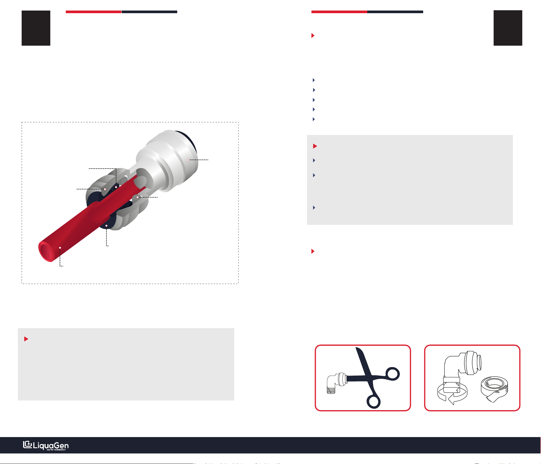
INSTRUCTION TO REPLACE DAMAGE
CONNECTORS
Take a pair of scissors and open them. Push one side into the broken
elbow and turn it anti-cockwise. The broken elbow should come out. Put
Teflon tape on the extra elbow which can be found in the box. With your
hand twist them on where the broken elbow was. Do not tighten the
elbows too much as they might break.
FIG 1# FIG 2#
PLEASE NOTE:
After installing the system and before running water, kindly make sure
all the tubing is properly pushed in and secure by first pulling and then
pushing all the tubing in.
All systems include extra connectors (elbows).
Tighten all canisters (housing) with the wrench before turing on the
water supply.
Take pair of scissors and open them.
Push one side into the broken elbow and turn it anti-clock wise.
Put Teflon tape on the extra elbow which can be found in the box.
With your twist them on where the broken elbow was.
Do not lighten the elbow too much as they might break.
HOW TO REPLACE
DAMAGE ELBOW
www.liquagen.comwww.liquagen.com
STEP 6: INSERT WHITE TUBE
09
Insert the white tubing in the
elbow connector.
Near the 3rd stage there should be
white tubing loose at the back of
the unit. This is NOT the white
tubing used for the outgoing water
connected to the ball valve.
Make sure you hear a slight click
sound to confirm the fitting is
properly secure.
CONNECTING THE SYSTEM
FOOD GRADED TUBING CONNECTIONS
Each tube color is designed for a specific purpose.
RED TUBING - Inserted in stage 1 (Sediment) and connects to the garden
hose adapter for the incoming cold water supply.
BLACK TUBING - Installed in stage 4 (RO Membrane Housing). It’s rejected
water and is essentially the water which is too impure to pass through your
system. This should go directly to your drain and we strongly advise not to
use this for any other applications.
WHITE TUBING - This is installed on your 5th stage (Inline DI Filter), which
is the line to provide ultra pure 0TDS water.
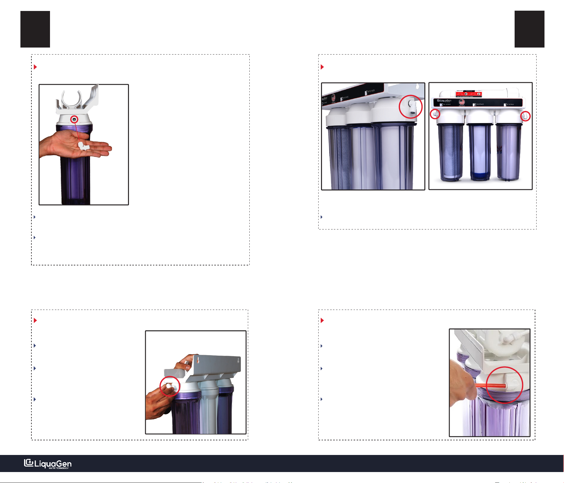
SYSTEM
ASSEMBLY 06
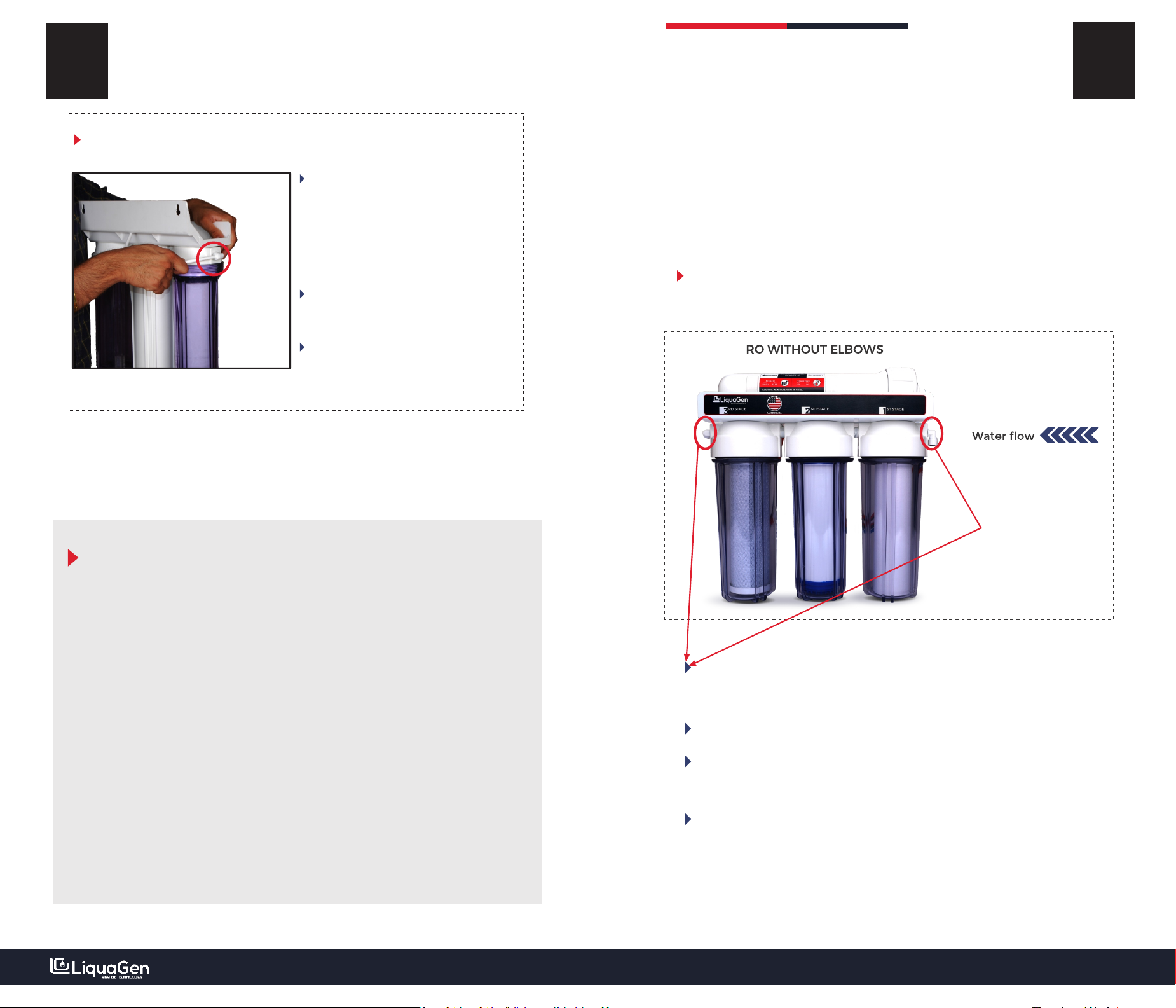
INSTALLING SIDE ELBOWS & INSERTING TUBES
STEP 1: QUICK OVERVIEW
⁰
The unit has two connectors (90 1/4“) which need to be installed on the
side of unit.
After installing the elbow connectors the tubing needs to be inserted.
We do not pre-installed them as they get damaged during the shipping
process.
System assembly is the same for RO/DI & portable/replacement
drinking water system.
www.liquagen.comwww.liquagen.com
STEP 4: DOUBLE CHECK
STEP 5: INSERT RED TUBE
Insert the red tubing in the elbow which
is near the first stage.
The red tube connects to your faucet
adapter or garden hose adapter and is
your incoming water supply.
Make sure you hear a sight click sound
that confirms the tubing is properly
secure.
Make sure all fittings are secure. #IMAGE2 is how the unit should look like.
#IMAGE 1 #IMAGE 2
08
STEP 2: ELBOW CONNECTOR
07
* We provide extra Teflon tape & connectors for emergencies.
STEP 3: INSERTING THE FITTINGS
Screw the elbow on to both sides of
the unit.
If the fittings break they are easy to
replace and at the end of the next
page we explain how to fix broken
elbows.
Make sure you do not tighten the
elbow too much or the fittings will
break.
In the box, there should be a small packet with all the fittings and Teflon
tape.
2 elbow will have Teflon tape pre-applied. Use those to screw into the end
of each side.
Other manuals for 6 stage
1
This manual suits for next models
2
Other LiquaGen Water Filtration System manuals

Popular Water Filtration System manuals by other brands


Patching Panda
Patching Panda MOON PHASE user manual

Waterman
Waterman SF 122 Operating and assembly instructions

Whirlpool
Whirlpool TITANIUM P-06CRS Use & care guide

brondell
brondell H625 Pearl owner's manual

Dupla
Dupla RO 270 quick start guide

Pentair
Pentair EVERPURE Twin Installation and operation guide


