MELAG MELAdem 47 User manual

User Manual
MELAdem® 47
Reverse osmosis unit
EN
Dear customer,
We thank you for your confidence demonstrated by the purchase of this MELAG product. As an owner-run and operated
family concern founded in 1951, we have a long history of successful specialization in hygiene products for practice-
based use. Our focus on innovation, quality and the highest standards of operational reliability has established MELAG
as the world’s leading manufacturer in the instrument reprocessing and hygiene field.
You, our customer are justified in your demand for the best products, quality and reliability. Providing “competence in
hygiene” and “Quality – made in Germany”, we guarantee that these demands will be met. Our certified quality man-
agement system is subject to close monitoring: one instrument to this end is our annual multi-day audit conducted in ac-
cordance with ENISO13485. This guarantees that all MELAG products are manufactured and tested in accordance with
strict quality criteria.
The MELAG management and team.


Contents
Contents
1 General guidelines ...............................................................................................................................................................4
Symbols used.......................................................................................................................................................................4
Formatting rules ...................................................................................................................................................................4
Disposal ...............................................................................................................................................................................4
2 Safety.....................................................................................................................................................................................5
3 Description of the device.....................................................................................................................................................6
Intended use ........................................................................................................................................................................6
Mode of functioning..............................................................................................................................................................6
Scope of delivery..................................................................................................................................................................7
View of the device ................................................................................................................................................................7
4 Setup and installation ..........................................................................................................................................................8
Installation location...............................................................................................................................................................8
Cold water connection..........................................................................................................................................................8
Assembly..............................................................................................................................................................................9
Connecting the device........................................................................................................................................................13
5 Commissioning...................................................................................................................................................................19
6 Maintenance........................................................................................................................................................................20
Maintenance intervals ........................................................................................................................................................20
Operating pauses...............................................................................................................................................................20
Removing and attaching the filter containers .....................................................................................................................21
Change the fine filter ..........................................................................................................................................................22
Changing the activated carbon filter...................................................................................................................................23
Replacing the mixed-bed resin cartridge............................................................................................................................24
7 Technical data ....................................................................................................................................................................25
8 Accessories and spare parts ............................................................................................................................................26
Glossary .................................................................................................................................................................................27

1 General guidelines
4
1 General guidelines
Please read this user manual carefully before commissioning the device. The manual includes important
safety instructions. Make sure that you always have access to digital or printed version of the user manual.
Should the manual no longer be legible, is damaged or has been lost, you can download a new copy from
MELAG download centre at www.melag.com.
Symbols used
Symbol Explanation
Indicates a dangerous situation, which if not avoided, could entail slight to life-
threatening injuries.
Draws your attention to a situation, which if not avoided, could result in damage to the
instruments, the practice fittings or the device.
Draws your attention to important information.
Formatting rules
Example Explanation
see Chapter 2 Reference to another text section within this document.
Disposal
MELAG devices are synonymous with high quality and a long life-span. When you eventually need to de-
commission your MELAG device, the required disposal of the device can take place with MELAG in Berlin.
Dispose of accessories and consumption media which you no longer require in the appropriate manner.
Comply with all relevant disposal specification in terms of possibly contaminated waste.
The packaging protects the device against transport damage. The packaging materials have been selec-
ted for their environmentally-friendly disposability and can be recycled. Returning the packaging to the ma-
terial flow reduces the amount of waste and saves raw materials.

2 Safety
5
2 Safety
When operating the device, comply with the following safety instructions as well as those
contained in subsequent chapters. Use the device only for the purpose specified in these
instructions. Failure to comply with the safety instructions can result in injury and/or damage to
the device.
Setup, installation and commissioning
nCheck the device after unpacking for any damage suffered during transport.
nWe recommend that the device only be setup, installed and commissioned by MELAG authorised per-
sons.
nInstall and operate the device in a frost-free environment.
Storage and transport
nStore and transport the device frost-free.
nAvoid strong shocks/vibrations.
nStore the device in a fashion protected against moisture.
Daily operation
nUse only original MELAG accessories or those from other stockists authorized for use by MELAG.
nNever operate the device unattended. Unsupervised operation of the device can result in damage to
the device or your facility. In such a case, MELAG does not accept any liability.
Leaks
nClose the water intake upon detecting a leak. Check all hoses and hose connections for leaks.
nOnly original MELAG spare parts may be used.

3 Description of the device
6
3 Description of the device
Intended use
The water treatment unit with ion exchanger permits the production of demineralised (deionised) water.
This requires tap water of drinking water quality.
PLEASE NOTE
The water treatment unit does not provide low-germ water.
The water treatment unit is suitable for the supply of one or more small steam sterilizers with feed water.
Furthermore demineralised water can be extracted, e.g. with the delivered removal valve. The water treat-
ment unit is intended for use in the medical field, e.g. in clinics, medical and dental practices and other
medical care facilities outside the patient environment.
The water treatment unit MELAdem 47 is not a medical device within the meaning of European Regulation
2017/745 on medical devices.
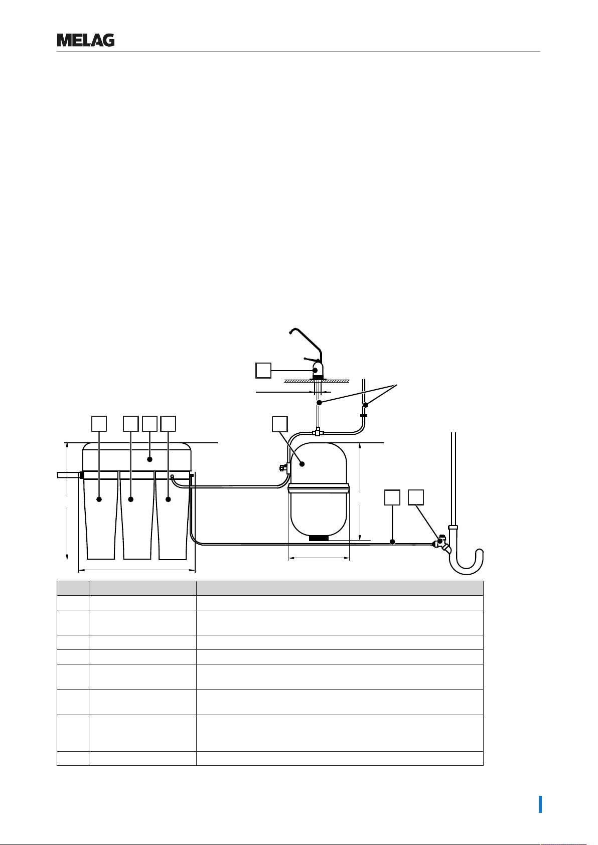
Mode of functioning
The water treatment unit works on the principle of reverse osmosis (reverse osmosis unit). This process
presses water through a semi-permeable RO membrane (osmosis module), reducing the salt content of
the cold water by some 95%. The inflowing water is separated into two flows:
▪ water with a low salt content (permeate)
▪ water with increased levels of salt (concentrate) which is disposed of via the outflow
An ion exchanger filled with mixed-bed resin is installed after the reverse osmosis unit to achieve the level
of water quality necessary for operation of the steam sterilizer, even with poor quality cold water. The ion
exchanger reduces the residual salt content of the permeate to a minimum. The permeate thus produced
is saved in the pressure tank, which is connected to the steam sterilizer via a hose. The cold water inflow
is switched off automatically when the pressure tank filled. All operating runs of the device are automatical-
ly controlled via its water pressure.
The permeate can be drawn through a separate removal valve for other uses.
The device can be can be connected directly with the following steam sterilizers for automatic water feed:
▪ Combination steam sterilizers (Careclave 618 using the MELAG pressure increase pump)
▪ Premium-Plus Class Evolution (Vacuklav 40 B+ Evolution, 41 B+ Evolution, 43 B+ Evolution, 44 B+
Evolution)
▪ Premium-Plus-Class (Vacuklav 40 B+, 41 B+, 43 B+, 44 B+)
▪ Premium-Class (Vacuklav 40-B, 41-B, 43-B, 44-B)
▪ Pro-Class (Vacuklav 23 B+, 24 B+, 24 BL+, 30 B+, 31 B+)
▪ S-Class (Euroklav 23 VS+, 29 VS+, 23 S+)
▪ Classic models (Vacuklav 23-B, 24-B, 24-B/L, 30-B, 31-B, Euroklav 23V-S, 29V-S, 23-S, 29-S)

3 Description of the device
7
Scope of delivery
Please check the scope of delivery before setting up and connecting the device.
Standard scope of delivery
▪ MELAdem 47
▪ User manual
▪ Record of installation and setup
▪ Warranty certificate
▪ Pressure tank
▪ Hose (black, 6mm)
▪ Removal valve
▪ Water inflow hose (2.5m)
▪ Connection set MELAdem47 (Filter for MELAdem incl.)
▪ Container key
View of the device
Depth: 18 cm
To the wastewater
connection of the steam
sterilizer
To the feed water connection
of the steam sterilizer
46 cm
40 cm
28 cm Ø 6 mm
Ø 1.5 - 3 cm
40 cm
Ø 6 mm
1234
67
8
5
Pos. Designation Description
1 Fine filter (pre-filter) Holds back all particulate material, rust and other soiling.
2 Activated carbon filter Removes free chlorine which can destroy the RO membrane in the
reverse osmosis unit.
3 Osmosis module The core of the reverse osmosis unit.
4 Ion exchanger Performs the demineralisation of the water from the osmosis module.
5 Pressure tank The permeate is collected here. The steam sterilizer is supplied with
feed water from the pressure tank.
6 Outlet hose The concentrate from the device is fed into the wastewater via the
outlet hose.
7 Wastewater connection The connection set is used to install the outlet hose of the reverse
osmosis unit and the outlet hose of the steam sterilizer to the building-
side outlet (e.g. sink siphon).
8 Removal valve Demineralised water is extracted for general use at the removal valve.

4 Setup and installation
8
4 Setup and installation
Installation location
uInstall the device in a clean, frost-free location that can be ventilated.
uThe installation location must permit careful installation, operation and maintenance.
uInstall the device in the proximity of a sink (e.g. in a sink floor unit) to facilitate connection to the cold
water line and the outflow.
uConnect the components in accordance with the installation plan (see View of the device [}page7]).
uA cut-off valve with a backflow preventer and a 3/4“ external thread connection should be installed in
close proximity to the installation location.
uTo ensure safe operation of the water treatment unit, the water pressure on the building side must be
between 2-6 bar.
uThe on-site requirements include proximity to an outlet line with a 1” external thread connection
(preferably a washing machine connection and then the sink siphon).
uMake sure that the temperature along the inlet hose does not rise above 40°C.
uIf the room in which the device is installed does not have a floor drain, a leakage water detector (water
stop, art. no. ME01056) is recommended, which shuts off the water supply in the event of damage via
a moisture sensor on the floor and with the aid of a solenoid valve.
Cold water connection
PLEASE NOTE
MELAG recommends connecting the water treatment unit directly to the drinking water.
Connecting water purification systems or filters that work with oxidants (e.g. chlorine)
upstream can affect the osmosis module and thus impair the performance of the water
treatment unit.
Increased requirements can be placed on the quality of the DI water (e.g. a low endotoxin content) for the
reprocessing of certain medical devices such as ophthalmic instruments. Comply with the following:
uIn such cases, an additional filter system is required for the reprocessing of DI water.
uIt is possible that the drinking water has been contaminated by the water installation. This includes the
domestic installation and pre-device periphery.
uArrange for a check of the drinking water quality at the removal point or request a report (e.g. from the
building management) before setting up and installing the device.
uFurther information is available from the corresponding trade associations and their publications. If in
doubt, contact your stockist or the pertinent professional association.
PLEASE NOTE
The yield (capacity) is an approximate guide value that depends on other factors in
addition to the water hardness. An upstream softening system with regeneration based
on common salt can lead to a reduction in the capacity of the MELAdem 47, regardless of
the set initial water hardness.
PLEASE NOTE
In case of increased water demand, e.g. when used with Careclave or when supplying
several steam sterilizers, it may be necessary to connect a pressure increase pump (art.
no. ME22500) upstream if the line pressure is low.

4 Setup and installation
9
The inlet of the water treatment unit is connected to a water tap with a ¾” pipe thread. The water inflow tap
must be fitted with a backflow preventer and a pipe aerator, to prevent the water from returning to the mu-
nicipal water system. Close the water tap at night, when it is out of use for several weeks and during repair
or maintenance work.
PLEASE NOTE
To prevent water damage, MELAG recommends the use of a leakage water detector e.g.
the MELAG water stop.
To ensure a standard-compliant connection of the water treatment unit with backflow preventer and a pipe
aerator independently of the building-side installation, MELAG recommends:
Method 1
}Installation of a separate water pipe (nominal width
DN15 with 1/2” socket) and installation of a water tap
with integrated safety combination (pos.a, art. no.
ME37310).
a
Method 2
}Installation of a cold water connection (e.g. a sink)
with an angle valve (pos.a) and pipe (pos.b, 10mm)
and the installation of an additional water inflow tap
with an integrated safety combination (pos.c, art. no.
ME58130) through direct assembly on the angle valve
already present.
c
b
a
Assembly
When planning the installation of the device, ensure sufficient space for the modules, a filter change, the
cover hood and the pipe connections. The module mounting is fixed in the desired position using the two
mounting drillholes.
The pressure tank can be installed anywhere in proximity to the steam sterilizer.
Using the manometer included in the scope of delivery, set the primary pressure on the valve on the un-
derside of the container to 0.4-0.5bar:
1. Primary pressure too high: Reduce the pressure by pushing in the valve tappet.
2. Primary pressure too low: Increase the pressure with the help of an air pump.

4 Setup and installation
10
Installing the removal valve
When positioning the removal valve, make sure that the normal water tap remains easily accessible.
1
2
3
4
5
6
7
8
9
10
11
12
13
14
1 Removal valve
2 Operating lever
3 Foot
4 Small rubber disc, black
5 Metal disc, white
6 Rubber disc, black
7 Tabletop
8 Bracket disc
9 Toothed lock washer
10 Nut
11 Reinforcing sleeve
12 Crimp
13 Union nut
14 Connection hose, 6mm
(permeate inflow pipe)
1. Drill a hole (Ø12mm) at the desired position on the
worktop.
2. Push the small black rubber disc (pos.4), the white
metal disc (pos.5) and the large black rubber disc
(pos.6) as close as possible to the removal valve
from below.
4
5
6
3. Insert the removal valve from above into the hole in
the worktop.
4. Position the removal valve so that it is ready for
use.

4 Setup and installation
11
5. Attach the bracket disc (pos.8), the toothed lock
washer (pos.9) and the nut (pos.10) to the base of
the removal valve. Make sure that the removal valve
does not twist when fastening the nut. After fastening
the nut, align the removal valve again with a spanner
if necessary.
8
9
10
6. Place the union nut (pos.13), the crimp (pos.12) and
the reinforcing sleeve (pos.11) on the connection
hose (pos.14). Please note: Cut connection hoses
that are too long to the desired length or replace
connection hoses that are too short with longer hoses
(PUR hose, black, 6 mm, length: 10 m, art. no.
ME28820, not included in the scope of delivery).
11
12
13
14
7. Attach the connection hose to the removal valve.
8. Tighten the union nut (pos.13).
13

4 Setup and installation
12
Installing the water discharge
uInstall the water discharge using the connection set (included in the scope of delivery) according to the
following illustration.
uInstall the water discharge preferably directly in front of the sink siphon.
uUse the enclosed copper seal or a Teflon tape (not included in the scope of delivery) to seal the parts.
1
234
6
5
7
Position Description Art. no.
1 Sink siphon*)--
2 Double hose fitting for siphon with backflow flaps ME37400
3 Wastewater adapter (G1/4” internal thread) ME56930
4 Copper seal for 1/4” --
5 Screw-in fitting 1/4” on hose 6 mm ME53450
6 Rubber seal 3/4“ for external water supply ME56950
7 Branch in front of siphon 1” external thread*)--
*) present on the building side
Installing hose connections between the components
NOTICE
Damage to the water treatment unit.
Hoses must not have any kinks, crimps or other damage.
The connection between the components of the water treatment unit is made by means of a black, pres-
sure-resistant hose (external diameter 6 mm; wall thickness 1 mm; a hose with a length of 6 m is included
in the scope of delivery). The required length depends on the local conditions. Cut hoses that are too long
to the desired length or replace connection hoses that are too short with longer hoses (PUR hose, black,
6 mm, length: 10 m, art. no. ME28820, not included in delivery).
1. Connect the hose on the removal valve to the T-piece on the pressure tank.
2. Insert the T-piece into the hose between the water treatment unit and the pressure tank.
3. Connect one end of this hose to the screw connection on the permeate outlet of the water treatment
unit (angled screw connection on the ion exchanger housing).
4. Connect the other end of the hose to the free connection on the T-piece of the pressure tank.
5. Connect the feed water supply hose to the free connection of the T-piece between the water
treatment unit and the pressure tank.
6. Insert feed water into the filter in the feed water hose.
7. Connect the screw-in fitting on the siphon to the concentrate outlet of the water treatment unit (on the
support plate behind the filter tank for the ion exchanger).
Alternatively, you can mount the feed water hose directly on the T-piece of the pressure tank and the hose
to the removal valve on the T-piece between the water treatment unit and the pressure tank.

4 Setup and installation
13
After installing the pressure tank, open the shut-off valve on the pressure tank (vertical position). Close the
shut-off valve on the pressure tank for maintenance and to change the filter or mixed-bed resin cartridge in
order to keep the stored demineralised water in the pressure tank.
Connecting the device
The connection of the MELAdem 47 depends on the device type of the steam sterilizer. The device can be
connected directly to the steam sterilizer.
PLEASE NOTE: Stand-alone devices collect the used feed water (wastewater) in the wastewater side of
the storage tank. Hot wastewater can run off the emergency overflow of a Vacuklav41B+/43B+. The
steam sterilizer must be connected to the existing siphon of the domestic water inlet or the double-cham-
ber wastewater trap from MELAG. MELAG also makes this recommendation for the
Vacuklav23B+/31B+.
When connecting to a stand-alone steam device, additional connection sets are required for supply and
wastewater (see Accessories and spare parts [}page26]).
NOTICE
Ensure that the hoses do not suffer kinking or crushing.
PLEASE NOTE
To prevent water damage, MELAG recommends the use of a leakage water detector e.g.
the MELAG water stop.
Connecting to a steam sterilizer with a fixed water connection
1. Remove the hose safety combination water inlet at the safety combination EN1717.
2. Connect the water inlet manifold (Y-piece) with the corresponding seal to the safety combination
EN1717.
3. Connect the hose safety combination water inlet to the water inlet manifold (Y-piece).
4. Connect the MELAdem47 inlet hose to the free connection of the water inlet manifold (Y-piece).
5. Connect the other end of the MELAdem47 inlet hose to the inlet of the water treatment unit.
6. Connect the free end of the feed water supply hose to the feed water connection of the steam
sterilizer.

4 Setup and installation
14
Installation example
Example 1 – Connection to Vacuklav 40 B+, 44 B+
1
13
2.2
3
5
12
2.4
6
2.3
4
9
10
8
2.8
7
2.7
2.6
11
2.1
2.5
8.1
2.9
Position Description Art. no. contained in
1 Safety combination EN 1717 incl. mount ME82375 --
2 MELAdem 47 reverse osmosis unit ME01047 --
2.1 Water inflow distributor Y-piece with seal ME37315 ME01047
2.2 External tap for demineralized water (removal valve) ME91900 ME01047
2.3 Filter for MELAdem ME48240 ME01047
2.4 Double hose fitting for siphon with backflow flaps ME37400 ME01047
2.5 Wastewater adapter (G1/4” internal thread) ME56930 ME01047
2.6 Pressure tank MELAdem 47 (with shut-off valve and hose) ME57065 ME01047
2.7 MELAdem 47 reverse osmosis unit (without accessories) ME56740 ME01047
2.8 Water inflow hose (2.5 m) (inlet hose MELAdem47) ME37220 ME01047
2.9 PUR hose, black, 6 mm, length: 10 m (inlet hose feed water) ME28820 ME01047
3 Hose safety combination water inflow*)ME25975 --
4 Solenoid valve “cooling water”*)ME46995 --
5 Feed water connection ME37242 --
6 Wall outlet NW40**)-- --
7 Double chamber siphon***)ME26635 --
8 Water outlet hose for steam sterilizers, 2 m***)ME36585 --
8.1 Wastewater nozzle for siphon with seal and clamp ME52615 ME36585
9 Connection piece for wastewater hose*)ME21334 --
10 Water stop (Leak water detector with cut-off valve and sensor,
optional)
ME01056 --
11 Tap water supply hose EN 1717, 2.5 m**)ME24930 --
12 Water tap with safety combination**)-- --
13 Mains connection**)-- --
*) present on the device side
**) present on the building side
***) included in the scope of delivery of the steam sterilizer

4 Setup and installation
15
Example 2 – Connection to Vacuklav 24 B+, 24 BL+, 30 B+
1
2
3
4
5
6.2
6.4
6.5
6.9
6.3 7
10
12
6.78
11
6.8
6.1
6.6
9
10.1
13
Position Description Art. no. contained in
1 Safety combination EN 1717 incl. mount*)ME82375 --
2 Tap water supply hose EN 1717, 2.5 m**)ME24930 --
3 Solenoid valve block, cooling water Vacuklav*)ME57715 --
4 Water stop (Leak water detector with cut-off valve and sensor,
optional)
ME01056 --
5 Water tap with safety combination***)-- --
6 MELAdem 47 reverse osmosis unit ME01047 --
6.1 Water inflow hose (2.5 m) (inlet hose MELAdem47) ME37220 ME01047
6.2 Filter for MELAdem ME48240 ME01047
6.3 PUR hose, black, 6 mm, length: 10 m (inlet hose feed water) ME28820 ME01047
6.4 Pressure tank MELAdem 47 (with shut-off valve and hose) ME57065 ME01047
6.5 Wastewater adapter (G1/4” internal thread) ME56930 ME01047
6.6 MELAdem 47 reverse osmosis unit (without accessories) ME56740 ME01047
6.7 Double hose fitting for siphon with backflow flaps ME37400 ME01047
6.8 External tap for demineralized water (removal valve) ME91900 ME01047
6.9 Water inflow distributor Y-piece with seal ME37315 ME01047
7 Feed water connection**)ME37242 --
8 Double chamber siphon***)ME26635 --
9 Wall outlet NW40***)-- --
10 Water outlet hose for steam sterilizers, 2 m**)ME36585 --
10.1 Wastewater nozzle for siphon with seal and clamp ME52615 ME36585
11 Mains connection***)-- --
12 Nozzle for wastewater (professional class)*)ME57705 --
13 Hose safety combination water inflow*)
Vacuklav30B+
Vacuklav24B+, Vacuklav 24BL+
ME25975
ME48475
--
--
--
*) present on the device side
**) not included in the scope of delivery
**) present on the building side

4 Setup and installation
16
Connecting to a stand-alone steam sterilizer
Installation example
To connect the MELAdem47 to a Vacuklav41B+ Evolution, 43B+ Evolution, 23B+ or 31B+, install the
feed water inlet connection for a hose diameter of 6x1 mm (see technical manual of the steam sterilizer).
MELAG recommends mounting the safety combination according to the following installation examples for
compliant operation according to EN1717.
1. Connect the MELAdem47 inlet hose to the safety combination EN1717.
2. Connect the other end of the MELAdem47 inlet hose to the inlet of the water treatment unit.
3. Connect the free end of the feed water supply hose to the feed water connection of the steam
sterilizer.
Example 1 – Connection to Vacuklav 41 B+, 43 B+
1.2
1.1
9
4.1
4.3
3.1
8
4.4
5
4.2
2
3.2
6
4.7 4.6
7
4.5
3.3
4.8
Position Description Art. no. contained in
1 Mounting set EN 1717 for MELAdem (optional) ME49600 --
1.1 Tap water supply hose EN 1717, 2.5 m ME24930 ME49600
1.2 Safety combination EN 1717 incl. mount ME82375 ME49600
2 One way drain*)-- --
3 Water connection set for Premium-Class (41 B+/43 B+) ME09034 --
3.1 Feed water connection of Euroklav/Vacuklav ME25655 ME09034
3.2 Water outlet hose for steam sterilizers, 2 m ME36585 ME09034
3.3 Cold water adapter (direct connection to water pipe) ME09037 ME09034
4 MELAdem 47 reverse osmosis unit ME01047 --
4.1 External tap for demineralized water (removal valve) ME91900 ME01047
4.2 Filter for MELAdem ME48240 ME01047
4.3 PUR hose, black, 6 mm, length: 10 m (inlet hose feed water) ME28820 ME01047
4.4 Double hose fitting for siphon with backflow flaps ME37400 ME01047
4.5 Wastewater adapter (G1/4” internal thread) ME56930 ME01047
4.6 Pressure tank MELAdem 47 (with shut-off valve and hose) ME57065 ME01047
4.7 MELAdem 47 reverse osmosis unit (without accessories) ME56740 ME01047

4 Setup and installation
17
Position Description Art. no. contained in
4.8 Water inflow hose (2.5 m) (inlet hose MELAdem47) ME37220 ME01047
5 Wall outlet NW40**)-- --
6 Double chamber siphon (optional) ME26635 --
7 Water tap with safety combination**)-- --
8 Mains connection**)-- --
9 Water stop (Leak water detector with cut-off valve and sensor,
optional)
ME01056 --
*) present on the device side
**) present on the building side
Example 2 – Connection to Vacuklav 23 B+, 31 B+
1.1
1.2
2
1.3
3
4.1
5.1
5.2
5.3
5.4
5.5
5.6
6
7
5.7
1.4
4.2
8
5.8
9
Position Description Art. no. contained in
1 Water connection set for Professional Class ME09033 --
1.1 Add-on kit for wastewater ME26695 ME09033
1.2 Disposable drain hose (PVC 23/15 mm, 5 m) ME36581 ME09033 /
ME26695
1.3 Feed water connection of Euroklav/Vacuklav ME25655 ME09033
1.4 Wastewater nozzle for siphon with seal and clamp ME52615 ME09033 /
ME26695
2 Water stop (Leak water detector with cut-off valve and sensor,
optional)
ME01056 --
3 Water tap with safety combination**)-- --
4 Mounting set (EN 1717) for MELAdem ME25410 --
4.1 Tap water supply hose EN 1717, 2.5 m ME24930 ME49600
4.2 Safety combination EN 1717 incl. mount ME82375 ME49600
5 MELAdem 47 reverse osmosis unit ME01047 --
5.1 Filter for MELAdem ME48240 ME01047
5.2 PUR hose, black, 6 mm, length: 10 m (inlet hose feed water) ME28820 ME01047
5.3 Pressure tank MELAdem 47 (with shut-off valve and hose) ME57065 ME01047
5.4 Water inflow hose (2.5 m) (inlet hose MELAdem47) ME37220 ME01047
5.5 MELAdem 47 reverse osmosis unit (without accessories) ME56740 ME01047
5.6 Wastewater adapter (G1/4” internal thread) ME56930 ME01047
5.7 Double hose fitting for siphon with backflow flaps ME37400 ME01047
5.8 External tap for demineralized water (removal valve) ME91900 ME01047

4 Setup and installation
18
Position Description Art. no. contained in
6 Double chamber siphon (optional) ME26635 --
7 Wall outlet NW40**)-- --
8 Mains connection**)-- --
9 Rear wall panel*)ME66790
*) present on the device side
**) present on the building side

5 Commissioning
19
5 Commissioning
NOTICE
Unsupervised operation of water consuming devices, including this water treatment unit
follows at the operator’s risk. Do not operate the device for a long period unsupervised,
e.g. over night. This could void the insurance cover for the building. MELAG accepts no
liability what so ever for any damage resulting from unsupervised operation.
In your absence, switch off the water shut-off valve or the central water shut-off.
ü
The cold water tap (tap water tap) is closed.
1. Loosen the hose screw connection from the reverse osmosis unit on the pressure tank.
2. Place the hose end in a drain or bucket.
3. Remove the filter container (see Removing and attaching the filter containers [}page21]).
4. Remove the mixed-bed resin cartridge.
5. Screw the empty filter container into the housing of the water treatment unit (see Removing and
attaching the filter containers [}page21]).
6. Remove the housing cover of the reverse osmosis unit.
7. Open the cold water tap.
8. Let the cold water run through the device for approx. 20 min to remove preservatives and dust
residues.
9. After flushing close the cold water tap.
10. PLEASE NOTE: The filter container is full to the brim with water. Unscrew and remove the ion
exchanger filter container.
11. Pour off the water in the filter container.
12. Return the mixed-bed resin cartridge (see Replacing the mixed-bed resin cartridge [}page24]).
13. Screw the ion exchanger filter container back on.
14. Screw the hose fitting from the reverse osmosis unit back onto the pressure tank.
15. Open the cold water tap.
16. Check that the device and the hose connections are tight.
17. Open the pressure tank shut-off valve completely.
PLEASE NOTE
Filling the pressure tank for the first time takes 1.5-2 h depending on the cold water
pressure. Only then can you remove a larger volume of the demineralised water
produced.
18. Check the water quality of the feed water at the removal valve with a conductivity meter if there is no
internal automatic conductivity measurement in the steam sterilizer.
19. Mount the housing cover on the reverse osmosis unit. The device now operates fully automatically.

6 Maintenance
20
6 Maintenance
Maintenance intervals
Interval Measure
Daily Control the permeate with a conductivity meter or using a steam sterilizer with inbuilt
conductivity measurement.
Every 12 months ▪ Maintain the water treatment unit as part of steam sterilizer maintenance.
▪ Replace the fine filter (pre-filter).
▪ Replace the activated carbon filter.
▪ Check the hoses and screw connections for leaks, swelling, crushing, kinks or
age-related brittleness.
▪ Check the primary pressure of the empty pressure tank.
Given poor local water quality, halve the intervals.
Every 6 years Replace all the hoses on the water treatment unit
As required With poor conductivity: Replace the mixed-bed resin cartridge in the ion exchanger.
The mixed-bed resin cartridges have an expiry date: Replace the mixed-bed resin
cartridges at the latest when the date expires.
Operating pauses
Depending on the length of the pause, perform the following measures:
Duration of the
operating pause
Measure
Up to 2 weeks Interrupt the cold water inflow.
Up to 4 weeks ▪ Interrupt the cold water inflow.
▪ Empty the pressure tank.
After 4 weeks ▪ Change the fine filter, activated carbon filter and mixed-bed resin cartridge.
▪ Empty the pressure tank.
▪ Before re-commissioning: Flush the water treatment unit and the pressure tank.
Other manuals for MELAdem 47
1
Table of contents
Other MELAG Water Filtration System manuals
Popular Water Filtration System manuals by other brands

ubbink
ubbink BioPressure 3000 manual

Omnifilter
Omnifilter PF500 installation instructions

HST
HST WFS-1545 Original instructions

Campbell Hausfeld
Campbell Hausfeld MP513803 operating instructions

Watts
Watts OneFlow OF220-2 Installation, operation and maintenance manual

Watts
Watts 315 Installation, operation and maintenance manual