Sfere SFR-AHF User manual
Multifunctional Active Filter
SFR-AHF
User Manual
12.2020

Please follow the warnings in this manual and use the symbols shown below
Danger
Warning of the personal injury or property damage.
Caution
Special attention should be payed.
If you have to install, star-up or maintain the device, you should consider the below
reasons:
Please read this manual carefully before using the device
If this device and the symbol are not followed properly with this manual
may cause personal injury or damage to equipment.
SFERE is subject to notice use the device and specifications of the components in this
manual.
SFERE will revise the latest version of the specification of the device and the User’s
manual on its official website.
Improper operation or installation may cause personal injury and
equipment damage. In particular, operating with voltage may cause
electric shock, it can cause death or serious injury. Installation or
maintenance may also cause fire. Please read this manual before
installation. Please obey the instruction of installation and maintenance
during the entire use life of the device. The National electric standard
should be noted.
Security considerations
Disclaimer

Content
1. Inspection................................................................................................................... 1
1.1 Acceptance........................................................................................................ 1
1.2 Transportation and delivery.............................................................................. 1
1.3 Storage...............................................................................................................3
2. Product description.................................................................................................... 4
3. Installation.................................................................................................................. 5
3.1 Before installation............................................................................................. 5
3.2 Location of installation and ventilation requirements......................................6
3.3 Installation.........................................................................................................8
3.4 Cable connection...............................................................................................9
3.5 Device terminal............................................................................................... 11
3.6 Cable connection.............................................................................................13
4. Operating..................................................................................................................16
4.1 Operational principle.......................................................................................16
4.2 Resonance detection.......................................................................................16
4.3 Main parameters confirmation before operation...........................................16
4.4 Start................................................................................................................. 17
4.5 System info...................................................................................................... 18
4.6 Data logging.....................................................................................................19
4.7 Wave curve...................................................................................................... 20
4.8 Harmonic......................................................................................................... 20
4.9 Settings............................................................................................................ 21
5. RJ45 communication................................................................................................ 29
6. Common maintenance............................................................................................. 36
6.1 Daily checking..................................................................................................36
6.2 Monthly checking............................................................................................ 36
6.3 Other checking................................................................................................ 36
7. Common problems...................................................................................................37

1
1. Inspection
1.1 Acceptance
Please check the following points after received the device:
a. Is the specification of the device consist to description of your order.
b. Is the device in good condition without any damages during transportation.
c. Check the appearance of the device before opening it.
d. Check if the user’s manual is attached.
e. Check the internal condition and external condition of the device before cable
connection.
1.2 Transportation and delivery
If the device needs to be moved in short distance, the support at the bottom of the
device can be operated by hydraulic trailer or forklift.(Fig. 1)
Fig. 1:Use the hydraulic trailer
If there is any problem when you receive the device, please contact the
courier and/or SFERE's after-sales service.
When transporting, loading, unloading and handling device, proper
protection measures must be taken and appropriate manual and
mechanical tools shall be used to avoid damage to the device. If the
device does not need to be installed immediately, be sure to store it on a
solid and level ground and follow the storage conditions listed in the
technical parameters section. In this case, the original protective
packaging of the device is recommended for storage.

2
When unloading and moving the device, use a forklift with a fork long enough to
support the entire bottom. The fork should be able to support at least 3 / 4 of the
bottom. Forks must be flat and have a firm bottom support. Lift the device by placing
the fork under the bottom of the packaging. (Fig.2).
Fig.2
When use knives or scissors to unfold the packaging of the device, make sure not to
damage the device.
Some models may have a high center of gravity. Therefore, when
transporting by forklift, it is recommended to firmly fix the device to
avoid sudden movement. The height of the device from the ground shall
not exceed 20cm.
The uneven distribution of components in the device might cause the
center of gravity of the equipment not coincide with the center point of
the outer box. Necessary precautions must be taken to prevent the
device from toppling in case of sudden operation.

3
1.3 Storage
The device should be storage in the following conditions:
Keep on the flat floor.
Keep in dry and well ventilated indoor storage.
Away from high temperature,maximum ambient temperature: +50℃
Away from salty and corrosive environment
Do not store the device in the durst accumulate places or the place with chemical or
some other pollution risks.
If the device is not installed immediately after receiving, the following
recommendations must be followed in order to keep the equipment in good
condition:
Keep the device in a dry environment with a temperature between - 20℃and 45℃
Away from direct sunlight
Keep the device in its original packaging.
If the AHF is not powered for a long time, a particular process must be adopted to
restore the internal medium of the busbar. The operation instruction given by Table 1
accordance with their storage period.
Table 1:Start-up process is determined by the length of the storage.
Storage
Process
≤1 Year
No special treatment is required
>1 Year
One hour power on at least before start-up
4
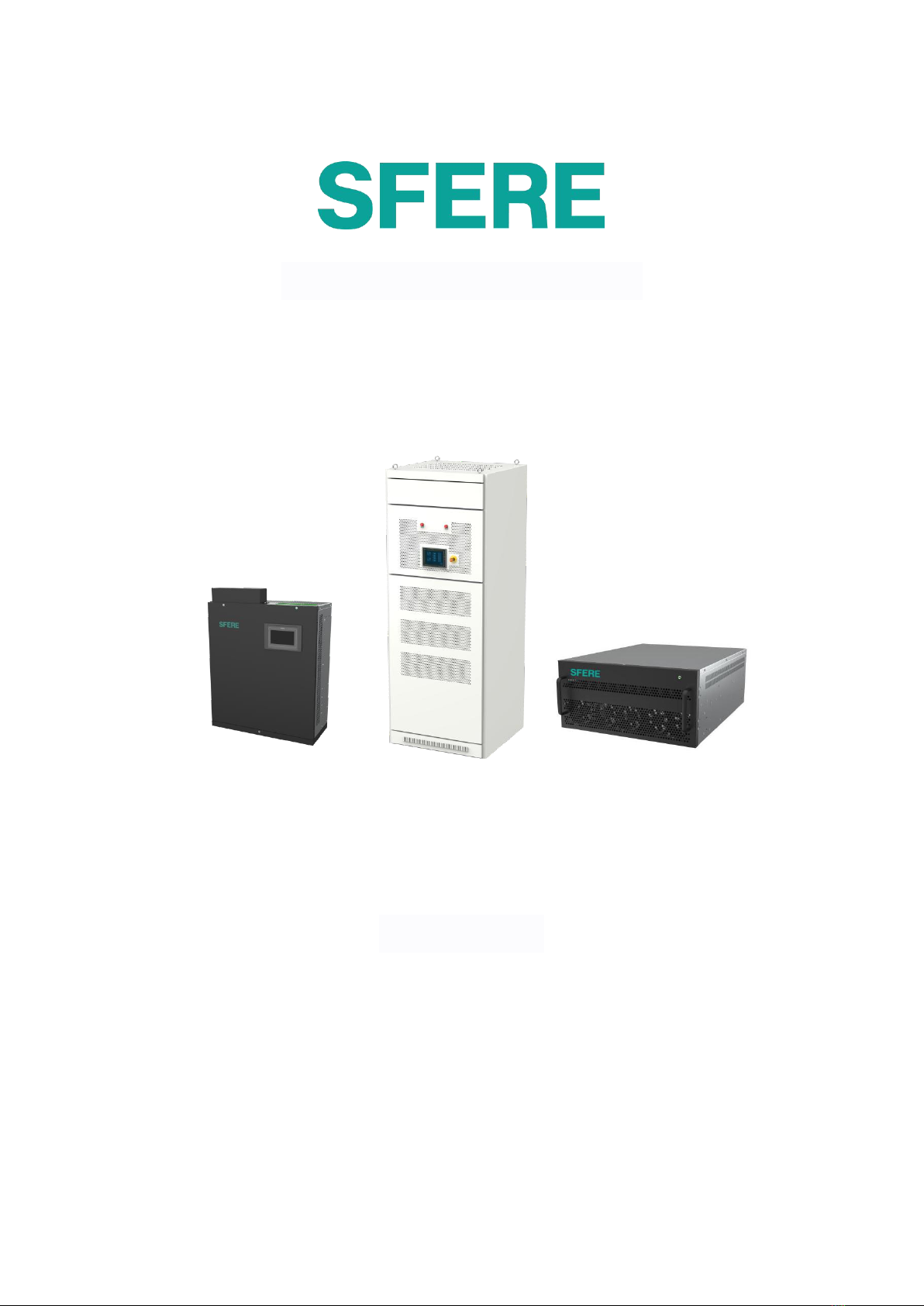
2. Product description
SFERE Active harmonic filters can be used to:
✓Reduce 2-51 harmonic current.
✓Power factor correction. It is suitable for inductive (-) and conductive (+) systems.
✓Adjust the three-phase imbalance of electrical system.
AHF Products can be used in three-phase three-wire system or three-phase four-wire
system.
AHF products can be purchased by module or whole cabinet.
Rack type AHF capacity:
50A/75A/100A/150A
Note: 7 inch HMI is defaulted, 10 inch HMI optional.

5
3. Installation
3.1 Before installation
Installation and maintenance of the device must be operated by trained
and qualified personnel.
Please turn off the main switch before carrying out any maintenance
operation of active harmonic filter.
Improper installation or setup of device will cause serious damage to the
device itself and other equipment in the system.
For your safety, any operation must follow the safety standards
specified in the Nation/Region, use the necessary personal protective
device (rubber gloves, mask and qualified fire-proof clothing) to prevent
the injury caused by electric shock or electric arc caused by discharging
the current carrying conductor, and pay attention to various warnings
which shown in this manual.
The device is not suitable for life support systems, medical safety
equipment or similar applications. The device is also not suitable for
military or defense purposes.
Assembly shall be carried out only on concrete floor in restricted access
areas or other non flammable meters.
Before power on, make sure that the device is properly grounded. In the
case of lightning or other transients, any poor grounding may cause
electric shock to the user and damage the device itself.

6
3.2 Location of installation and ventilation requirements
3.2.1 The installation environment of the device must meet the
following conditions:
The external temperature of the cabinet is between - 20 ℃to 45 ℃, the maximum
humidity is 95%, no condensation.
Do not install the device in a high temperature environment,avoid direct sunlight.
3.2.2 Ventilation requirements
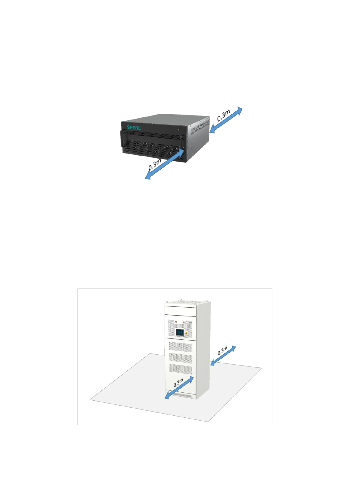
3.2.2.1 AHF Module
The AHF module applies forced ventilation cooling system, air intake on the front
panel, air outlet at the rear side. It must be ensured the air could be flow freely after
installation. At maximum power, the air flow speed of AHF module is 375 m³/h.
AHF module contains with the power control system,it could control the fan speed
and maximum power by the internal temperature. In order to maintain the best
performance of the AHF module under any conditions.
For the performance of the device,should guaranty the free air circulation of the AHF
module front panel,no obstruction at the rear, at least 300mm space.
Please note that the outward hot air may be sucked back by the fan of the device,
resulting in hot air back flow, thus reducing the performance of the device. The
situation is depending on the installation conditions of the cabinet and the external
environment of the device.
Before operating the current transformer, ensure that the secondary
circuit is short circuited. Do not open the secondary circuit of current
transformer under operation.
Please install the device away from water, dust, flammable liquids,
flammable gases and corrosive substances.
Make sure there is no reactive power compensation equipment sharing
the power supply with sfere AHF is installed.
If there is any,they must be turned harmonious, equipped with reactor
to prevent interference.
7
When selecting the installation location, the power consumption of the device
should be considered to ensure proper air re-circulation and inlet air temperature.
Fig.3
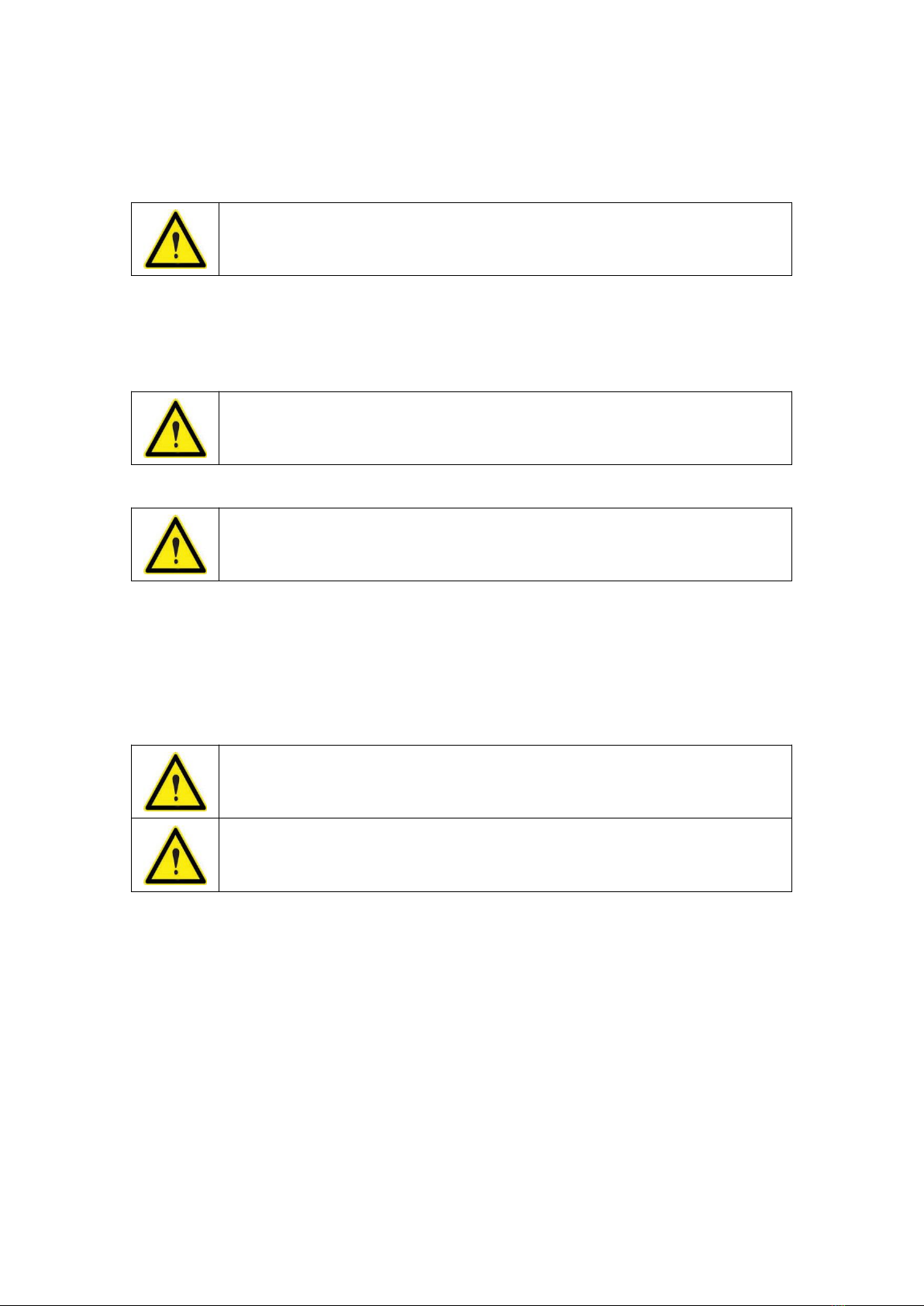
3.2.2.2 AHF Cabinet
AHF cabinet use forced ventilation and cooling system, with air inlet on the front
plate and air outlet at the rear of the module.
Do not block the ventilation grille on the top of the cabinet, leave enough space on
the top to dissipate heat. The specific distance depends on the surrounding
environment characteristics of the installation location.
Fig.4

8
3.3 Installation
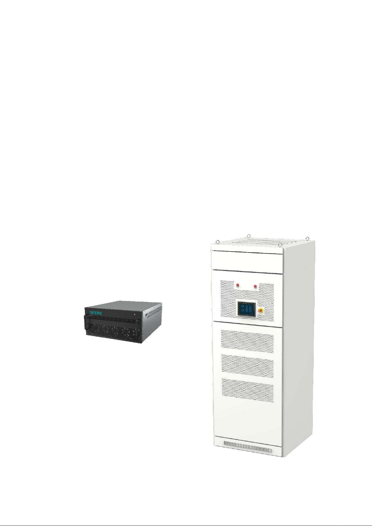
3.3.1 AHF Module
50A-75A racked-type module height is 189mm, 100A-150A racked-type module
height is 240mm.
Fig.5
Fig.6
9
Multiple rack mounted AHF modules can be installed in one cabinet.
Install the modules in the cabinet as follows:
1. Extend the anti tilt support of rack type whole cabinet.
2. Open or remove the door of the cabinet.
3. Place the AHF module on the track or shelf of the cabinet. Make sure they support
the weight of the module; use cross brackets if necessary.
4. Fix the module to the fixed point. use 4 * M6 fixing screws.
3.3.2 AHF Cabinet
AHF Cabinet is a complete cabinet body with 4 supports above the ground.
3.4 Cable connection
Use cables that meet the rated current of the filter and meet the requirements of the
installed national standards.
It is recommended that BVR or RV copper core cables with rated dielectric strength
of AC 0.6kv/1kv and allowable working temperature up to 70 ℃are selected as
primary cables. The sectional area of the cable is as follows:
Unless the rack type cabinet is fixed on the ground, its anti tilting feet
must be extended and fixed on the ground to ensure maximum safety
during installation.
Do not use the front handle to move the module.
Please install the module with the help of others.
The mounting surface must be firm and level to support the weight of
the device.
Do not use arc welding to weld the cabinet to the ground, as this may
cause damage to internal components.

10
Table 2
Capacity
L1 L2 L3
Main circuit incoming line
N line
PE line
50A
25mm²
The Line-N cable is
1.5 times of the
copper core of the
three-phase
Line-1,Line-2,Line-3
main circuit cable.
(Note: there is no
Line-N for 3L AHF;
Line-N is available for
4L AHF)
25mm²
75A
50mm²
25mm²
100A
50mm²
25mm²
150A
50mm²
35mm²
200A
70mm²
50mm²
300A
95mm²
70mm²
400A
120mm² or 2 * 70mm²
95mm²
450A
150mm² or 2 * 70mm²
120mm²
550A
185mm² or 2 * 95mm²
150mm²
600A
240mm² or 2 * 120mm²
185mm²
Make sure the equipment is properly grounded to prevent electric shock
hazard.
In order to measure the current accurately, it is recommended to use
0.2S class current transformer.
The right connection of the current transformer is very important for
the normal operation of Sfere AHF. If L1, L2 and L3 mixed positions, the
filter will not work properly.
Sfere AHF has built-in fuse over-current protection element.
Please install the external protection equipment according to the device
type, maximum short circuit current, fusing current and current
regulations of installation place.
11
The capacity of the active harmonic filter must match the harmonic current to be
filtered and conform to the electrical characteristics of the device.
Fig.7
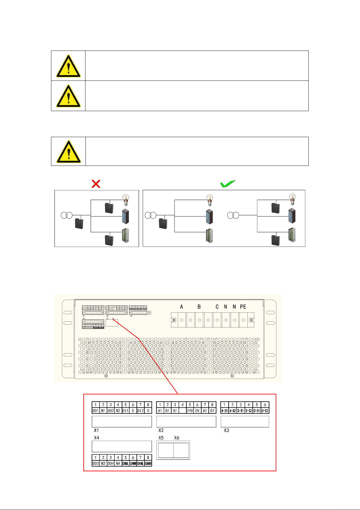
3.5 Device terminal
3.5.1 Rack type AHF
Fig.8
Table 3
If leakage protection is required by local regulations, only type B RCD
can be used. The AHF uses direct current inside. In case of failure, the
direct current may lead to the failure of type a RCD device.
Make sure the equipment installed in your distribution system (TN, VT,
it) meets current standards.
Do not install multiple filters in series connection within one harmonic
filtering system. It may cause over filtering for power instability (Fig.7).

12
Port type
Number
Function/description
X1 Control
signal port
DO1
Output of device fault relay
N1
DO2
Output of device relay on operation
N2
DI1
Device stop input port
(connected to external closed stop button)
C
DI2
External start switch input port
(connected to external open start / stop button)
C
X2
Communication
signal port
A1
External communications
B1
G1
Empty
24V
Power output positive + 24 V (power supply to HMI
touch screen)
0V
Power output negative pole 0V (power supply to HMI
touch screen)
A2
RS485 serial port with HMI touch screen+
B2
RS485 serial port with HMI touch screen-
X3
CT signal port
A-S1
S1 input port of A-phase current detection (connected
with S1 of A-phase transformer)
A-S2
S2 input port of A-phase current detection (connected
with S2 of A-phase transformer)
B-S1
S1 input port of B-phase current detection (connected
with S1 of B-phase transformer)
B-S2
S2 input port of B-phase current detection (connected
with S2 of B-phase transformer)
C-S1
S1 input port of C-phase current detection(connected
with S1 of C-phase transformer)
C-S2
S2 input port of C-phase current detection (connected
with S2 of C-phase transformer)
X4 port
DO3
Alarm Relay Output 1
N3
DO4
Alarm Relay Output 2
N4
Empty
Empty
X5/X6
Online with other modules via network cable
13
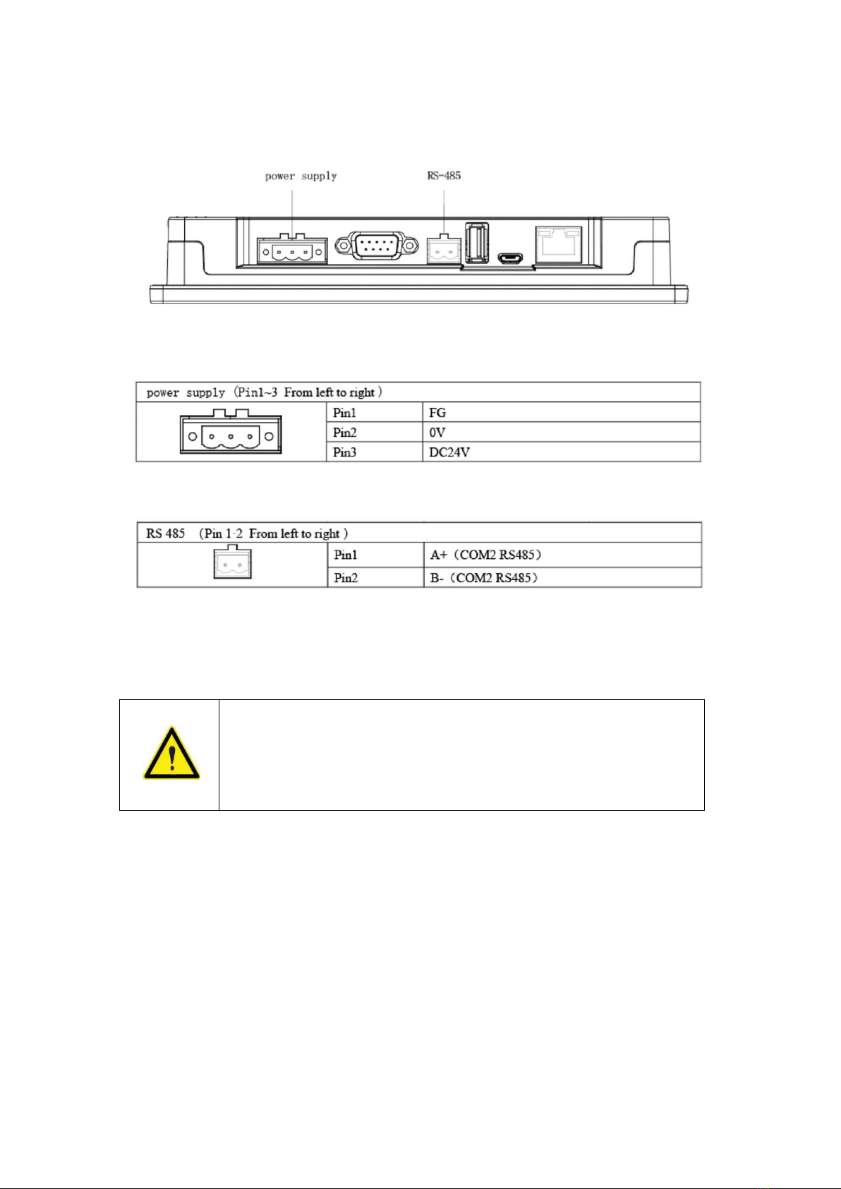
3.5.2 HMI
Table 4
Table 5
3.6 Cable connection
The main circuit wiring mode is shown in the figure. The connection shall ensure that
the phase sequence of the power grid is consistent with that of the device.
Otherwise, the device may not start normally. The installation direction of the
transformer is shown in the figure, and the P2 surface must be close to the load. S1
and S2 of each transformer must correspond to the port of corresponding label, and
open circuit at secondary side is strictly prohibited (open circuit may cause
transformer burnout).
Power supply equipment (e.g. transformer) should be off before
connecting all cables;
Make sure the power cable connection phase sequence is correct;
Adopt correct power distribution mode to ensure the safety of
module and user equipment;

14
3.6.1 Three phase four wire network side current measurement
Fig. 9
The CT configuration should be "grid side" when the CT is located in front of PCC
point.
3.6.2 Three phase four wire load side current measurement
Fig.10
When the CT is located behind PCC point, the CT configuration should be "load side"
15
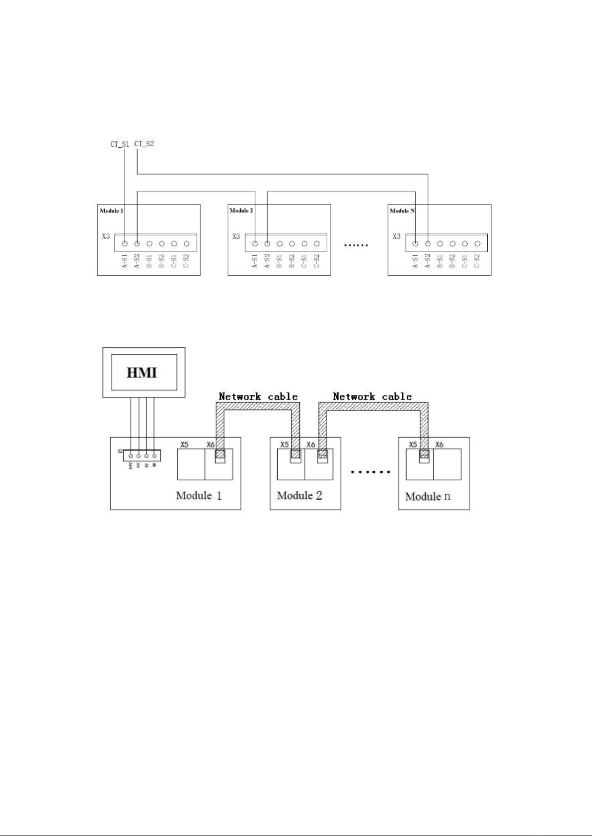
3.6.3 Connection diagram of CT lines for parallel operation of multiple
modules (Take Phase-A current as an example)
Fig.11
3.6.4 Connection diagram of multi-module parallel communication line
Fig.12
16
4. Operating
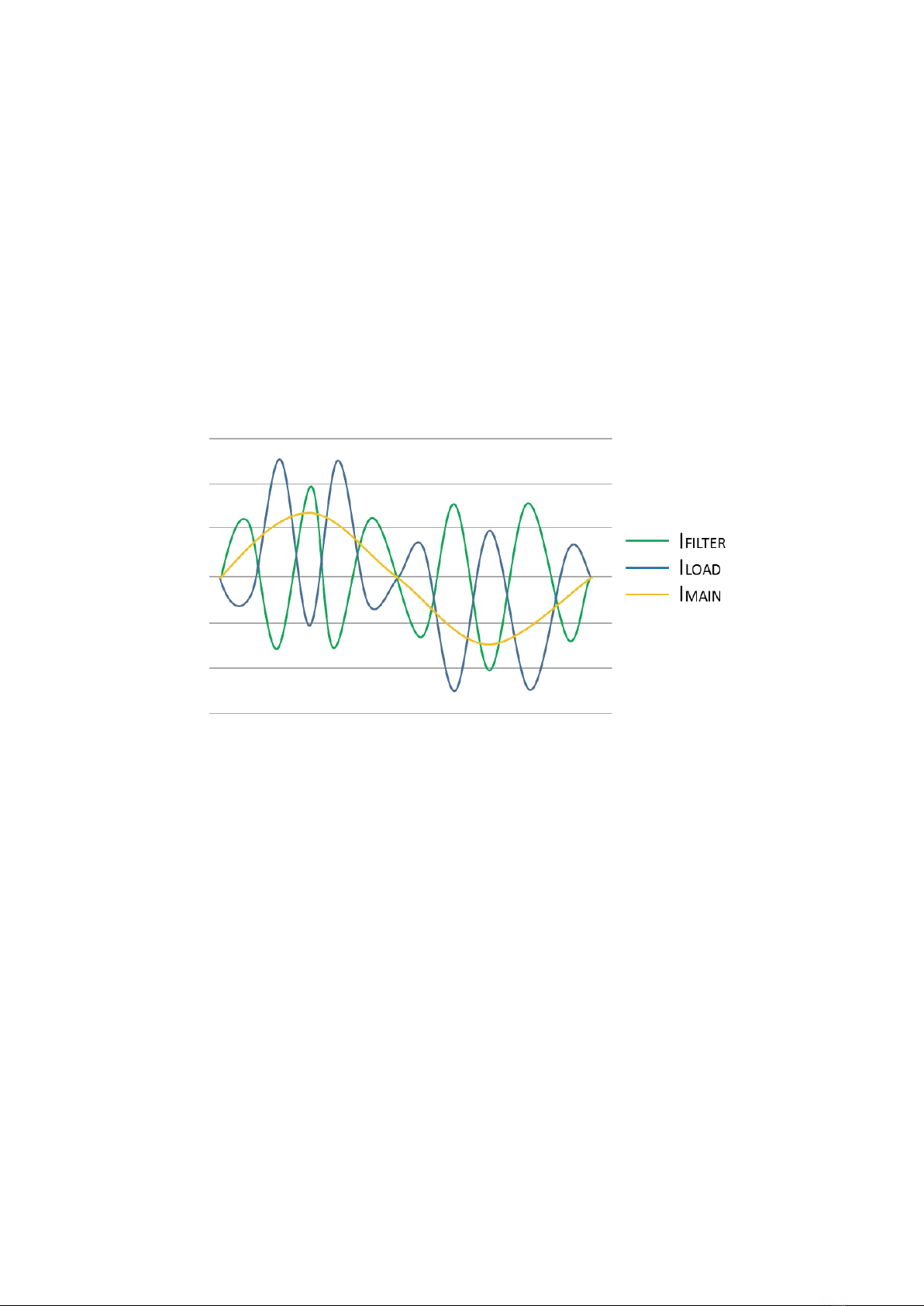
4.1 Operational principle
Active harmonic filters work as follows:
I filter=I main-I load
In other words, they can detect the difference from the desired sine wave of the
current (I main) and harmonic (I load) deformation signal, then injecting the
differential current (I load) before the two waveform .
Fig.13 shows the current waveform injected by the active filter.
These data are the expected waveform (I main), the existing distorted waveform (I
load) and the filter current (I filter).
Fig.13:I load,I main,I filter
4.2 Resonance detection
AHF will monitor and determine the occurrence of resonance in the system in real
time, adjust the compensation current automatically, and reduce the amplitude and
energy of resonance.
4.3 Main parameters confirmation before operation
After the installation of the device, confirm that the electrical connection of the
system is correct and power on.
1)Confirm the reliable connection between the device shell and the protective
ground to prevent the housing from being charged.
2) Check and confirm the distribution mode of the device, all power cables and
signal cables are connected correctly without short circuit.
3) Check and confirm that all input switches are disconnected and put warning
signs at these switches to prevent others from operating the switches。

17
4.4 Start
4.4.1 Light up the screen
The screen lights up after the power supply is powered on, enters the boot self-check,
carries on the inspection communication, the automatic network assignment address
and the initialization and so on work.
Fig. 14
4.4.2 Main interface
After the progress bar is loaded to 100%, it enters the main interface of the system
(Fig .15). The home page provides:
1 system information
2 event recording
3 waveform curve
4 harmonic
5 setting
6 help
Total 6 functions, in which the setting needs to log in and enter
Fig.15
At this point, the boot is complete, you can view information or parameter settings
and other operations
Table of contents
Popular Water Filtration System manuals by other brands


Biorock
Biorock ECOROCK-5000 Installation and user guide

West Marine
West Marine 13915137 instructions

Parker Hiross
Parker Hiross ESG2 user manual

DEKA Controls
DEKA Controls TOH Series installation manual

Envirco
Envirco MAC 10 LEAC Installation operation & maintenance

BWT
BWT Woda-Pure Clear S Installation and operating manual

Deltec
Deltec MCE 600 Operating instructions and spare parts list

Grizzly
Grizzly G5955 owner's manual

BWT
BWT Protector mini HWS C/R Installation and operating instructions

Oxyline
Oxyline X7N11 manual

BLUE COLLECTION
BLUE COLLECTION KIVI quick start guide

Watts
Watts PWFGAC1 Installation, operation and maintanance manual