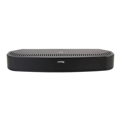
and point them towards the
tneeds a clear line-of-sightpath to the
The units can be mounted on the ceiling,
wall, or desk with the mounting hardware
(included). The threaded connectors on
the top and bottom of the units are a
tripods. These threaded connectors can
also be used to connect two units together.
For more detailed information see user’s manual: http://www.listentech.com/support/manuals/
+1.801.233.8992
+1.800.330.0891 North America
+1.801.233.8995 Fax
LT-84 Setup:
Plug power supply into the unit. Connect desired audio input signal
to one of the three input connector types on channel 1, 2, or both.
Turn power switch to the indicator lights on position . Adjust audio
level input knob up until the audio level LEDs are solid green with an
smis-
sion frequency and turn on the channel transmission switch. Once the
unit is adjusted, the power switch can be turned to the indicator lights
Note: LT-84 and Receivers need to be on the same frequency/channel
for proper operation.
LA-141 Setup:
141s
to the LT-84 via a CAT-5e 24 AWG cable; up to 2 LA-141s can be daisy
chained to each Expansion Link Output RJ-45 connector with a daisy
chain maximum cable length of 100 ft. (30 m). Turn the LT-84 and
LA-141 power switches to the position. Under normal operation
the green and amber LEDs on the RJ-45 connector of both the LT-84
and LA-141 will be illuminated.
Set Delay Compensation. For a single channel application, set both
Channel 1 and 2 Delay Compensation switches to the same setting. For
a two channel application, set Delay Compensation switches channel 1
and 2 independently. Pick appropriate frequency row, then move over
to the overall cabledistance from the LT-84 to the LA-141 being set,
thisis the switch setting.
Connection:
Cable Length 1 to 9 ft. 10 to 19 ft. 20 to 29 ft. 30 to 39 ft. 40 to 49 ft.
0.3 to 2.8 m 3 to 5.8 m 6 to 8.8 m 9.1 to 11.9 m 12.2 to 14.9 m
2.3 MHz 0 3 3 3 3
2.8 MHz 3 3 3 3 3
3.3 MHz 3 3 2 2 2
3.8 MHz 2 2 2 2 2
Delay Compensation Switch Setting
Cable Length 50 to 59 ft. 60 to 69 ft. 70 to 79 ft. 80 to 89 ft. 90 to 100 ft.
15.2 to 18 m 18.3 to 21 m 21.3 to 24 m 24.4 to 27.1 m 27.4 to 30.5 m
2.3 MHz 3 3 3 3 3
2.8 MHz 2 2 2 2 2
3.3 MHz 2 2 1 1 1
3.8 MHz 1 1 1 1 0
Olympus.QRG.rev.indd 2 11/12/14 4:56 PM
LT-84
Power
Power Supply
Microphone (Electret)
Unbalanced Audio Source
MIC RCA
Phoenix
Connector
Cat-5e
(24 AWG)
LA-141 (Optional)
LA-141 (Optional)
Balanced Audio Source
Cat-5e
LA-141 (Optional)
LA-141 (Optional)
Cat-5e
LT-84 Setup:
Plug power supply into the unit. Connect desired audio input
signal to one of the three input connector types on channel 1,
2, or both. Turn power switch to the indicator lights on
position . Adjust audio level input knob up until the audio
level LEDs are solid green with an occasional red flicker with
audio peaks. Select the desired transmission frequency and
turn on the channel transmission switch. Once the unit is
adjusted, the power switch can be turned to the indicator
lights off position if desired .
Note: LT-84 and Receivers need to be on the same
frequency/channel for proper operation.
LA-141 Setup:
Turn the LT-84 power switch to the off position. Connect the
LA-141s to the LT-84 via a CAT-5e 24 AWG cable; up to 2
LA-141s can be daisy chained to each Expansion Link Output
RJ-45 connector with a daisy chain maximum cable length of
100 ft. (30 m). Turn the LT-84 and LA-141 power switches to
the position. Under normal operation the green and amber
LEDs on the RJ-45 connector of both the LT-84 and LA-141 will
be illuminated.
Set Delay Compensation. For a single channel application,
set both Channel 1 and 2 Delay Compensation switches to the
same setting. For a two channel application, set Delay
Compensation switches channel 1 and 2 independently.
Pick appropriate frequency row, then move over to the overall
cable distance from the LT-84 to the LA-141 being set, this is
the switch setting.
Connection:
For more detailed information see user’s manual:
http://www.listentech.com/support/manuals/
14912 Heritage Crest Way, Bluffdale, Utah 84065-4818
+1.801.233.8992
+1.800.330.0891 North America
+1.801.233.8995 Fax
20171027
Cable Length
1.3 MHz
2.8 MHz
3.3 MHz
3.8 MHz
1 to 9 ft.
0.3 to 2.8 m
0
3
3
2
10 to 19 ft.
3 to 5.8 m
3
3
3
2
20 to 29 ft.
6 to 8.8 m
3
3
2
2
30 to 39 ft.
9.1 to 11.9 m
3
3
2
2
40 to 49 ft.
12.2 to 14.9 m
3
3
2
2
Cable Length
1.3 MHz
2.8 MHz
3.3 MHz
3.8 MHz
50 to 59 ft.
15.2 to 18 m
3
2
2
1
60 to 69 ft.
18.3 to 21 m
3
2
2
1
70 to 79 ft.
21.3 to 24 m
3
2
1
1
80 to 89 ft.
24.4 to 27.1m
3
2
1
1
90 to 100 ft.
27.4 to 30.5
3
2
1
0
Delay Compensation Switch Setting
Copyright © 1998 - 2018 Listen Technologies Corporation. All rights reserved.
Patented technology (pat. 9,712,246)
