Litewave 240511 User manual

www.litewave.co.uk Flexible LED Tape (240511) R3
1
Installation
Although the product is tested after manufacturing, it is highly advisable to test the Flexible LED Tape before cutting or fixing
in place to make sure it has not been damaged in transit, and that it is the correct colour.
To test Connect the red (+) wire of the LED Tape to the positive wire of a 12 Volt DC Switchmode Power Supply* (a 9v pp3
will also work for testing), then connect the black wire of the LED Tape to the negative (-) wire of the power supply (or pp3
battery). Ensure that all of the LEDs are fully lit, but AVOID VIEWING THE LEDS DIRECTLY.
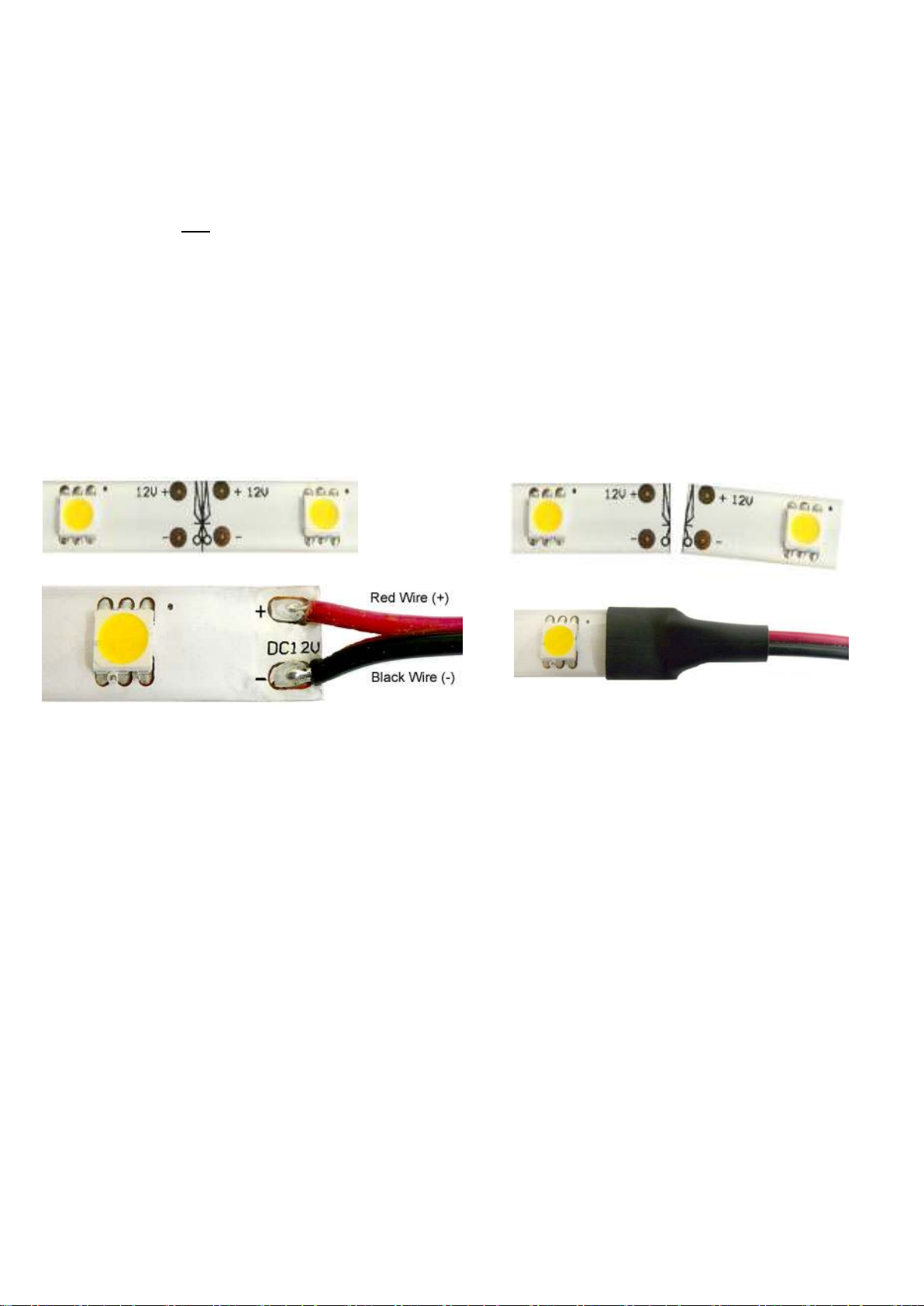
The LED Tape has two wires at both ends each with a small black connector (only 1 end needs to
be connected to the power) you will need to remove one black connector only. If the other end
connector or wire at the opposite end of the LED Tape is removed or cut it should be insulated to
avoid the possibility of short-circuit.
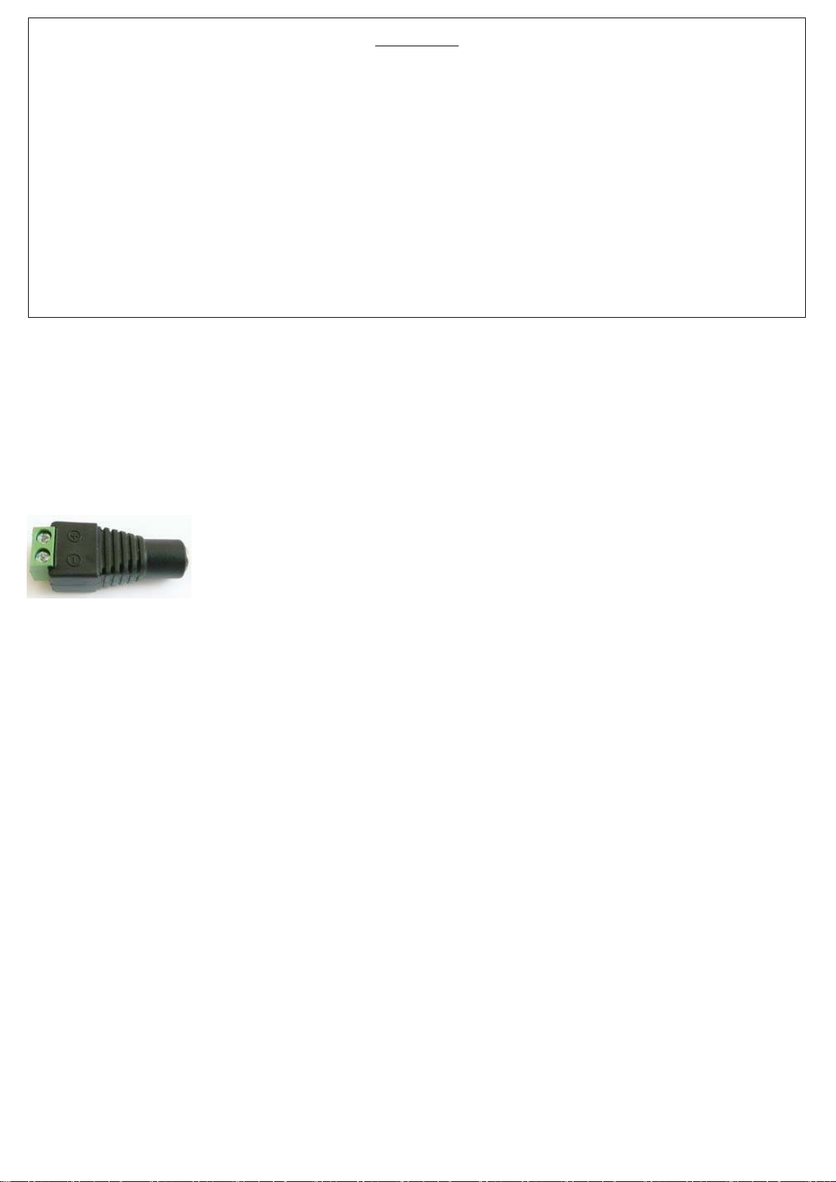
The wires can be connected to the output of the power supply with the DC Adaptor supplied (5A
is the maximum load that should be put on it), alternatively you could use a terminal block, or bullet connectors. Whatever
the connection method the wires should be located in the dry. Remove the small black connector from the wire of the LED
Tape so that you can connect the wires to the terminal block. The LED Tape will only light if connected the right way around
with the + output of the power supply to the + input of the LED Tape, this is usually the red wire.
Next identify the location where the Tape is to be fixed. Do not fix the Tape where it will be permanently wet. With suitable
insulation covering any exposed wired connections the tape will not be damaged by moderate amounts of atmospheric
moisture or the occasional water spray. If the tape is powered-up while submerged in water there is a risk of short-circuit and
possibly even fire in the long term. Equally, do not affix the tape directly to a metal surface as there is a risk of creating a
short-circuit on the back of the tape if accidentally perforated.
Once the location for the Tape has been decided upon simply remove the 3M Adhesive backing strip and carefully lay the
Tape in place working from one end to the other ensuring there are no raised sections. Using a lint-free cloth gently press
between the LEDs on the tape to remove any air bubbles and activate the adhesive, however, make sure you do not press
directly on the LEDs themselves as this could damage them.
Wiring
The 2 wires from the LED Tape can be extended if necessary by using any low-voltage 2-Core cable with a current rating of 3
Amps or greater. With long cable runs the use of a cable with a higher current rating will ensure minimal voltage-drop in the
wiring which could otherwise affect the brightness. 6M of LED Tap is th maximum r comm nd d l ngth for a
continuous run (spur) or join d l ngths otherwise brightness may not appear uniform along the entire length and the Tape
may be overloaded. If longer runs are required, and the power supply has adequate capacity, additional lengths should be
wired back directly to the supply forming separate spurs. The tape itself is unsuited to carrying more than 3 Amps so do not
extend it with excess lengths or other types of current load.
If a power supply having a significantly greater current capacity than the current requirement of the LED product(s) is to be
used then a safety fuse will be required along the positive input wire to the product. This is to prevent excess current flowing
WARNING
WARNINGWARNING
WARNING
Before use please remove the LED Tape from its bag and allow the odour to dissipate in an unused room or
outdoor building. Wash Hands after handling.
This product uses High Brightness LEDs. Direct viewing of the SMD LEDs at close range should be avoided.
Keep product away from children.
Clean the LED Tape with damp a tissue only.
Litewave LTD. Will not accept responsibility for any other issues arising from improper use or fitting of this product
where such matters are beyond our control.
Having highlighted a number of safety issues and warnings in this installation guide Litewave LTD. will accept NO
responsibility for issues arising from any failure to comply with these instructions and recommendations.

www.litewave.co.uk Flexible LED Tape (240511) R3
2
through the supply wiring and LED product(s) under fault conditions such as accidental damage. Such a fuse must be located
as near to the supply or driver to protect the installation wiring and shall have a current rating just higher than the total load
anticipated under normal operating conditions anticipated in the spur. Each additional Spur will require its own separate fuse.
We do not advise using the product in a vehicle, you fit to a vehicle at your own risk. PLEASE NOTE: If using in a vehicle or
on a vehicle battery it is ss ntial to use an in-line fuse along the + input to the LED Tape, if unsure consult a qualified
vehicle electrician. Follow the cable ratings on next page for the appropriate amperage fuse.
Not that a fuse may only be omitted from the low voltage side if the power supply provides its own overload protection and
is unable to significantly exceed the maximum rating of the wiring and LED product before it trips.
If hard-wiring th input of th Pow r Supply to th AC mains it is ss ntial to us a fus d wall switch or outl t.
Th fus on th mains sid should b 3A or l ss. Only a qualifi d l ctrician should hard-wir th Mains PSU.
Pow r Suppli s should b install d in a dry location.
Cutting and joining th Tap
A
lthough we advise against cutting the LED Tape because this will affect your warranty, we have provided a brief guide of
how to cut and join the tape below. NOTE: Wh n sold ring always do so in a w ll v ntilat d ar a and w ar a mask.
You need to cut the tape along the line with the 4 solder pads on either side of the cut. Carefully remove 5-8mm of the resin
taking care not to cut into the tracks of the pcb, this can be done with a sharp stanley knife (always use sharp tools carefully),
be careful not to damage the tracks underneath if cutting through the resin. Make sure you have removed all of the resin on
and around the solder pads.
Be careful when soldering that you do not overheat the pads as this heat can damage the pad and the LEDs, a small dab of
flux paste helps with a fast solder connection. Mak sur th wir you us is rat d for load.
Apply a small blob of solder to each copper solder pad. Before soldering the wire to the pads it is best to apply a small
amount of solder to each of the wires to tin the wires this will prevent the wires from becoming frayed and causing a short-
circuit. Then solder the red wire to the positive (+) solder pad, and solder the black wire to the negative (-) pads as shown.
The soldered joints must be insulated to prevent accidental short-circuits and moisture ingress. Liberal application of Silicone
Sealant or Hot-Melt Glue are recommended as is adhesive-lined Heat-Shrink Sleeve if available. On LED Tape with with an
overall protective coating the applied insulation should seal all the way up to and around the coating and to where the wires
exit the heat shrink to prevent water ingress.
Warranty
This product is warranted from manufacturing defect only. This warranty is valid for 1 year from the date of purchase. This
warranty does not apply to damage caused by user installation or normal wear and tear. Cutting the tape will automatically
void your warranty, so do so carefully. If a segment becomes faulty only that part can be replaced under warranty once cut.
Litewave LTD. gives no warranty against damage to any surface due to applying or removing this product. Please follow
instructions and heed all warnings carefully.

www.litewave.co.uk Flexible LED Tape (240511) R3
3
Sp cifications
Voltage 12 Volts DC
Viewing Angle: 120 Degrees
Maximum current drain Approx. 0.5 Amps (500ma) per Meter
LED Type SMD
Light Output 200 Lumens/m
Durability Lightly Splashproof (If Tape is cut connections need to be resealed). Pre-fitted connectors
are not waterproof.
Cabl and fus rating:
(round up if n c ssary):
500mm = 250mA 1M = 500mA 2M = 1Amp 4M = 2Amp 6M = 3Amp
Important: Installation by qualifi d l ctrician r comm nd d.
IMPORTANT Saf ty Information:
- Keep away from children, this is not a toy.
- DO NOT place or fit the LED Tape near sources of heat or naked flames. Do not install on flammable material.
- Not recommended for use outdoors or in e treme temperatures.
- Ma imum length of Tape is 6 Meters do not e ceed or e tend.
- The Tape should not be installed around tight or angled bends as it may cause the resin to crack. It must be installed in a
straight line. DO NOT curl or twist the LED Tape whilst power is on. The LED Tape can be bent on it’s flat side but should
not be fle ed sideways.
- The LED Tape should be removed from the reel before powering.
- Soldered connections should not cause a short across the tracks. Connections should be sealed with hot glue or silicone
and heat shrink or adhesive lined heat shrink.
- Assembly or connections must not damage or destroy conducting paths on the circuit board. The LED Tape itself and all its
components should not be mechanically stressed.
- Installation of LED Tape (with power supplies) needs to be made with regard to all applicable electri
cal and safety standards.
- We advise a qualified electrician perform entire installation.
- Correct electrical polarity needs to be observed. Wrong polarity may destroy the LED Tape.
- Parallel connection is highly recommended as safe electrical operation mode.
- Serial connection is not recommended. Unbalanced voltage drop can cause hazardous overload and damage the LED Tape.
- Please ensure that the power supply is of sufficient power to operate the total load.
- * Only power the LED Tape with a 12vdc Switchmode Power Supply (constant voltage). Do not use a constant current
Power Supply. Do not e ceed the load of the Power Supply. The Power Supply should conform to Class 2 and SELV
standards.
- Fi ing to conductive or metal surfaces is not recommended. If fi ing on metallic or otherwise conductive surfaces, there
should be an electrical insulator between LED Tape and the mounting surface to prevent possible short-circuit.
- All LEDs are static sensitive.
- Damaged by corrosion will not be honored as a materials defect claim. It is the user’s responsibility to provide suitable
protection against corrosive agents such as moisture and condensation and other harmful elements.
-Identify Positive (+) and negative (-) outputs of the Power Supply by using a multimeter.
-Electrical Connections and joints should be in a dry area unless adequately sealed.
LITEWAVE LTD. MAKES NO WARRANTY, EITHER EXPRESSED OR IMPLIED, INCLUDING BUT NOT LIMITED TO ANY IMPLIED WARRANTIES OF
MERCHANTABILITY OR FITNESS FOR A PARTICULAR PURPOSE, REGARDING THESE LITEWAVE LTD. MAKES PRODUCTS AVAILABLE SOLELY
ON AN “AS-IS” BASIS. IN NO EVENT SHALL LITEWAVE LTD. BE LIABLE TO ANYONE FOR SPECIAL, COLLATERAL, INCIDENTAL, OR
CONSEQUENTIAL DAMAGES IN CONNECTION WITH OR ARISING OUT OF PURCHASE OR USE OF LITEWAVE PRODUCTS. THE SOLE AND
EXCLUSIVE LIABILITY TO LITEWAVE LTD, REGARDLESS OF THE FORM OF ACTION, SHALL NOT EXCEED THE PURCHASE PRICE OF THE
LITEWAVE PRODUCT DESCRIBED HERE IN.
Environm ntal Information
At the end of this product’s usable life it should be disposed of according to WEEE regulations, which means it should be taken to
your local municipal site for safe disposal/recycling.
Table of contents
Other Litewave Lighting Equipment manuals